Liquid interfaces in viscous straining flows ... - Itai Cohen Group
Liquid interfaces in viscous straining flows ... - Itai Cohen Group
Liquid interfaces in viscous straining flows ... - Itai Cohen Group

You also want an ePaper? Increase the reach of your titles
YUMPU automatically turns print PDFs into web optimized ePapers that Google loves.
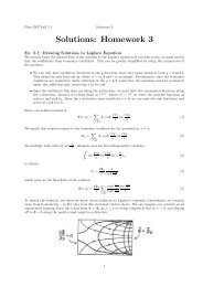
178 M. Kle<strong>in</strong>e Berkenbusch, I. <strong>Cohen</strong> and W. W. Zhangwithdrawal to <strong>viscous</strong> entra<strong>in</strong>ment corresponds to a threshold capillary number Ca c<strong>in</strong> the range of 10 −3 . Thus surface tension effects are strong even at the transition.3.1. M<strong>in</strong>imal modelThese results from the two-layer <strong>viscous</strong> withdrawal experiment motivate the follow<strong>in</strong>gidealization. S<strong>in</strong>ce the conta<strong>in</strong>er size is much larger than the characteristic length scaleof the hump, the two immiscible liquid layers are taken as <strong>in</strong>f<strong>in</strong>ite <strong>in</strong> extent and <strong>in</strong>depth. We use a cyl<strong>in</strong>drical coord<strong>in</strong>ate system where z = 0 corresponds to the heightof the undisturbed flat <strong>in</strong>terface and r = 0 is the centrel<strong>in</strong>e of the withdrawal flow. Todrive the withdrawal, we prescribe a s<strong>in</strong>k flow˜Qu ext (x) =4π|x S − x| (x 3 S − x), (3.2)where x S = ˜Se z corresponds to a s<strong>in</strong>k placed at height ˜S above the undisturbed<strong>in</strong>terface and ˜Q is the strength of the po<strong>in</strong>t s<strong>in</strong>k. This choice allows ˜S to be the onlylength scale imposed on the flow, consistent with the experimental observation thatthe hump shape depends primarily on the height of the withdrawal tube S p and noton its diameter.In the experiment, the tube height S p is either comparable to, or smaller than,the capillary length scale l γ . This is a different situation from the geophysical <strong>flows</strong>exam<strong>in</strong>ed by Lister (1989), for which l γ ≪ S p . Because the capillary length scaleis small relative to the characteristic length scale of geophysical <strong>flows</strong>, the <strong>in</strong>terfacedeformation analysed by Lister levels out on a large length scale, one where hydrostaticpressure effects are more significant than surface tension effects. As a result, the forcebalance relevant for how the <strong>in</strong>terface levels out is a balance between <strong>viscous</strong> stressesand hydrostatic pressure. In contrast, when l γ ≫ S p , a limit not exam<strong>in</strong>ed by Listerbut more relevant for the selective withdrawal experiments, the <strong>in</strong>terface deformationlevels out on a length scale much shorter than the capillary length scale. As aresult, the relevant force balance responsible for the flatten<strong>in</strong>g of the <strong>in</strong>terface is thatbetween surface tension and <strong>viscous</strong> stresses. This motivates us to treat the far-fieldcondition differently from Lister’s analysis. Instead of explicitly <strong>in</strong>clud<strong>in</strong>g the effectof hydrostatic pressure, we require that the <strong>in</strong>terface has zero deflection at r = a.Physically, this p<strong>in</strong>n<strong>in</strong>g location a corresponds roughly to the capillary length scalel γ . In the calculation, the slope of the <strong>in</strong>terface at r = a is adjusted so that the p<strong>in</strong>n<strong>in</strong>gcondition is satisfied at all flow rates. This <strong>in</strong>troduces an error <strong>in</strong> the <strong>in</strong>terface shapenear r = a. This error is guaranteed to be small when the s<strong>in</strong>k height ˜S is far smallerthan a. It is small even when ˜S is comparable with a. In§ 4.3, we also show that,provided l γ >S p , <strong>in</strong>clud<strong>in</strong>g the hydrostatic pressure explicitly does not change ourresults.F<strong>in</strong>ally, s<strong>in</strong>ce the <strong>in</strong>terface evolution is observed to rema<strong>in</strong> essentially the same evenas the layer viscosities are made unequal, we assume the two liquids have exactly thesame viscosity. These assumptions mean that the flow dynamics <strong>in</strong> the upper layersatisfies∇·σ 1 = −∇p 1 + μ∇ 2 u 1 = 0, ∇·u 1 = 0, (3.3)where u 1 is the disturbance velocity field created <strong>in</strong> the upper layer ow<strong>in</strong>g to thepresence of the liquid <strong>in</strong>terface, p 1 is the pressure and σ 1 is the stress field associatedwith the disturbance velocity field u 1 . Note that u ext is a solution of Laplace’s equationand therefore gives rise to a uniform and constant pressure distribution. The flow <strong>in</strong>the lower layer is created solely via the flow <strong>in</strong> the upper layer past the <strong>in</strong>terface.