Modeling and Simulation of Vehicular Power Systems - webfiles its ...
Modeling and Simulation of Vehicular Power Systems - webfiles its ...
Modeling and Simulation of Vehicular Power Systems - webfiles its ...

You also want an ePaper? Increase the reach of your titles
YUMPU automatically turns print PDFs into web optimized ePapers that Google loves.
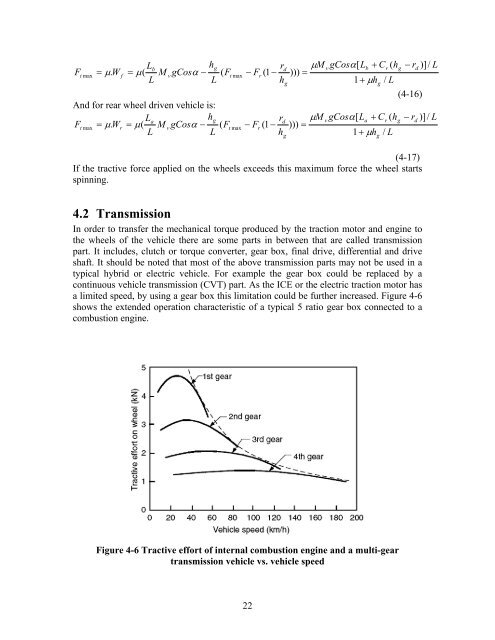
Ft maxLhbg= μ. Wf= μ(MvgCosα− ( FtmaxLLAnd for rear wheel driven vehicle is:LhagFtmax= μ. Wr= μ(MvgCosα− ( FtmaxLLr− Fr(1 −hdgμM))) =vgCosα[Lb1+μh+ C ( hgr/ Lr μMvgCosα[La+ Cr( hdg− Fr(1 − ))) =h1+μh/ Lggg− r )]/ Ld( 4-16)− r )]/ L( 4-17)If the tractive force applied on the wheels exceeds this maximum force the wheel startsspinning.d4.2 TransmissionIn order to transfer the mechanical torque produced by the traction motor <strong>and</strong> engine tothe wheels <strong>of</strong> the vehicle there are some parts in between that are called transmissionpart. It includes, clutch or torque converter, gear box, final drive, differential <strong>and</strong> driveshaft. It should be noted that most <strong>of</strong> the above transmission parts may not be used in atypical hybrid or electric vehicle. For example the gear box could be replaced by acontinuous vehicle transmission (CVT) part. As the ICE or the electric traction motor hasa limited speed, by using a gear box this limitation could be further increased. Figure 4-6shows the extended operation characteristic <strong>of</strong> a typical 5 ratio gear box connected to acombustion engine.Figure 4-6 Tractive effort <strong>of</strong> internal combustion engine <strong>and</strong> a multi-geartransmission vehicle vs. vehicle speed22

![LAPLACE OPERATOR.ppt [Lecture seule]](https://img.yumpu.com/42909900/1/190x135/laplace-operatorppt-lecture-seule.jpg?quality=85)