Modeling and Simulation of Vehicular Power Systems - webfiles its ...
Modeling and Simulation of Vehicular Power Systems - webfiles its ...
Modeling and Simulation of Vehicular Power Systems - webfiles its ...

Create successful ePaper yourself
Turn your PDF publications into a flip-book with our unique Google optimized e-Paper software.
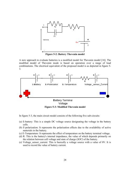
Figure 5-2: Battery Thevenin modelA new approach to evaluate batteries is a modified model for Thevenin model [16]. Themodified model <strong>of</strong> Thevenin mode is based on operation over a range <strong>of</strong> loadcombinations. The electrical equivalent <strong>of</strong> the proposed model is as depicted in figure 5-3.Figure 5-3: Modified Thevenin modelIn figure 5-3, the main circuit model consists <strong>of</strong> the following five sub-circu<strong>its</strong>:(a) E-battery: This is a simple DC voltage source designating the voltage in the batterycells.(b) E-polarization: It represents the polarization effects due to the availability <strong>of</strong> activematerials in the battery.(c) E-Temperature: It represents the effect <strong>of</strong> temperature on the battery terminal voltage.(d) R: This is the battery's internal impedance, the value <strong>of</strong> which depends primarily onthe relation between cell voltage <strong>and</strong> state <strong>of</strong> charge (SOC) <strong>of</strong> the battery.(e) Voltage_sensor_current: This is basically a voltage source with a value <strong>of</strong> 0V. It isused to record the value <strong>of</strong> battery current.28


![LAPLACE OPERATOR.ppt [Lecture seule]](https://img.yumpu.com/42909900/1/190x135/laplace-operatorppt-lecture-seule.jpg?quality=85)