Modeling and Simulation of Vehicular Power Systems - webfiles its ...
Modeling and Simulation of Vehicular Power Systems - webfiles its ...
Modeling and Simulation of Vehicular Power Systems - webfiles its ...

You also want an ePaper? Increase the reach of your titles
YUMPU automatically turns print PDFs into web optimized ePapers that Google loves.
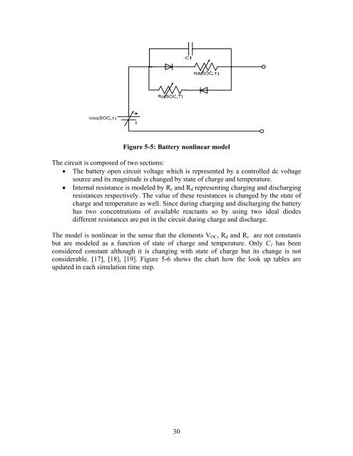
Figure 5-5: Battery nonlinear modelThe circuit is composed <strong>of</strong> two sections:• The battery open circuit voltage which is represented by a controlled dc voltagesource <strong>and</strong> <strong>its</strong> magnitude is changed by state <strong>of</strong> charge <strong>and</strong> temperature.• Internal resistance is modeled by R c <strong>and</strong> R d representing charging <strong>and</strong> dischargingresistances respectively. The value <strong>of</strong> these resistances is changed by the state <strong>of</strong>charge <strong>and</strong> temperature as well. Since during charging <strong>and</strong> discharging the batteryhas two concentrations <strong>of</strong> available reactants so by using two ideal diodesdifferent resistances are put in the circuit during charge <strong>and</strong> discharge.The model is nonlinear in the sense that the elements V OC , R d <strong>and</strong> R c are not constantsbut are modeled as a function <strong>of</strong> state <strong>of</strong> charge <strong>and</strong> temperature. Only C 1 has beenconsidered constant although it is changing with state <strong>of</strong> charge but <strong>its</strong> change is notconsiderable. [17], [18], [19]. Figure 5-6 shows the chart how the look up tables areupdated in each simulation time step.30


![LAPLACE OPERATOR.ppt [Lecture seule]](https://img.yumpu.com/42909900/1/190x135/laplace-operatorppt-lecture-seule.jpg?quality=85)