

SERVICE HANDBOOK
SERVICE HANDBOOK
SERVICE HANDBOOK

You also want an ePaper? Increase the reach of your titles
YUMPU automatically turns print PDFs into web optimized ePapers that Google loves.
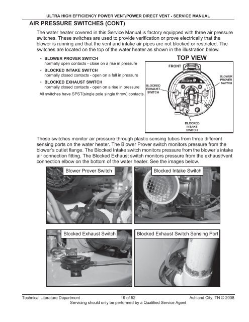
ULTRA HIGH EFFICIENCY POWER VENT/POWER DIRECT VENT - <strong>SERVICE</strong> MANUALAIR PRESSURE SWITCHES (CONT)The water heater covered in this Service Manual is factory equipped with three air pressureswitches. These switches are used to provide verification or prove electrically that theblower is running and that the vent and intake air pipes are not blocked or restricted. Theswitches are located on the top of the water heater as shown in the illustration below.• BLOWER PROVER SWITCHnormally open contacts - close on a rise in pressure• BLOCKED INTAKE SWITCHnormally closed contacts - open on a fall in pressure• BLOCKED EXHAUST SWITCHnormally closed contacts - open on a rise in pressureAll switches have SPST(single pole single throw) contacts.FRONTTOP VIEWThese switches monitor air pressure through plastic sensing tubes from three differentsensing ports on the water heater. The Blower Prover switch monitors pressure from theblower’s outlet flange. The Blocked Intake switch monitors pressure from the blower’s intakeair connection fitting. The Blocked Exhaust switch monitors pressure from the exhaust/ventconnection elbow on the bottom of the water heater. See the images below.Blower Prover SwitchBlocked Intake SwitchBlocked Exhaust SwitchBlocked Exhaust Switch Sensing PortTechnical Literature Department 19 of 52 Ashland City, TN © 2008Servicing should only be performed by a Qualified Service Agent


