

SERVICE HANDBOOK
SERVICE HANDBOOK
SERVICE HANDBOOK

Create successful ePaper yourself
Turn your PDF publications into a flip-book with our unique Google optimized e-Paper software.
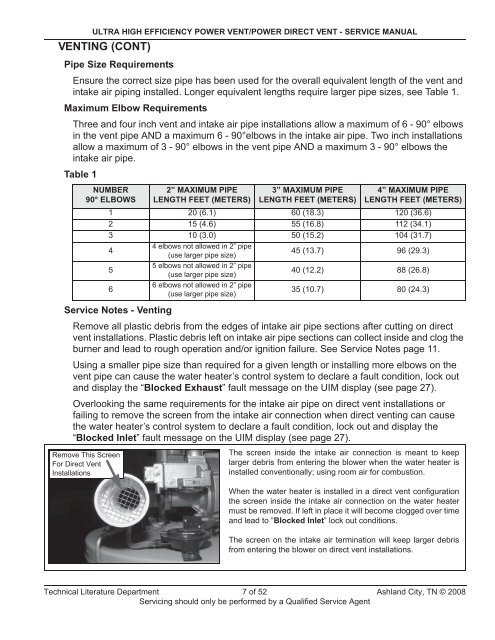
ULTRA HIGH EFFICIENCY POWER VENT/POWER DIRECT VENT - <strong>SERVICE</strong> MANUALVENTING (CONT)Pipe Size RequirementsEnsure the correct size pipe has been used for the overall equivalent length of the vent andintake air piping installed. Longer equivalent lengths require larger pipe sizes, see Table 1.Maximum Elbow RequirementsThree and four inch vent and intake air pipe installations allow a maximum of 6 - 90° elbowsin the vent pipe AND a maximum 6 - 90°elbows in the intake air pipe. Two inch installationsallow a maximum of 3 - 90° elbows in the vent pipe AND a maximum 3 - 90° elbows theintake air pipe.Table 1NUMBER90° ELBOWS2” MAXIMUM PIPELENGTH FEET (METERS)3” MAXIMUM PIPELENGTH FEET (METERS)4” MAXIMUM PIPELENGTH FEET (METERS)1 20 (6.1) 60 (18.3) 120 (36.6)2 15 (4.6) 55 (16.8) 112 (34.1)3 10 (3.0) 50 (15.2) 104 (31.7)44 elbows not allowed in 2” pipe(use larger pipe size)45 (13.7) 96 (29.3)55 elbows not allowed in 2” pipe(use larger pipe size)40 (12.2) 88 (26.8)66 elbows not allowed in 2” pipe(use larger pipe size)35 (10.7) 80 (24.3)Service Notes - VentingRemove all plastic debris from the edges of intake air pipe sections after cutting on directvent installations. Plastic debris left on intake air pipe sections can collect inside and clog theburner and lead to rough operation and/or ignition failure. See Service Notes page 11.Using a smaller pipe size than required for a given length or installing more elbows on thevent pipe can cause the water heater’s control system to declare a fault condition, lock outand display the “Blocked Exhaust” fault message on the UIM display (see page 27).Overlooking the same requirements for the intake air pipe on direct vent installations orfailing to remove the screen from the intake air connection when direct venting can causethe water heater’s control system to declare a fault condition, lock out and display the“Blocked Inlet” fault message on the UIM display (see page 27).Remove This ScreenFor Direct VentInstallationsThe screen inside the intake air connection is meant to keeplarger debris from entering the blower when the water heater isinstalled conventionally; using room air for combustion.When the water heater is installed in a direct vent configurationthe screen inside the intake air connection on the water heatermust be removed. If left in place it will become clogged over timeand lead to “Blocked Inlet” lock out conditions.The screen on the intake air termination will keep larger debrisfrom entering the blower on direct vent installations.Technical Literature Department 7 of 52 Ashland City, TN © 2008Servicing should only be performed by a Qualified Service Agent


