

SERVICE HANDBOOK
SERVICE HANDBOOK
SERVICE HANDBOOK

You also want an ePaper? Increase the reach of your titles
YUMPU automatically turns print PDFs into web optimized ePapers that Google loves.
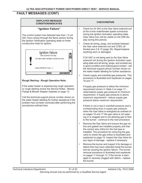
ULTRA HIGH EFFICIENCY POWER VENT/POWER DIRECT VENT - <strong>SERVICE</strong> MANUALFAULT MESSAGES (CONT)DISPLAYED MESSAGECONDITION/INDICATES“Ignition Failure”The control system has detected less than 1.0 μA(DC micro amps) through the flame sensor duringthe Ignition Verification operating state on threeconsecutive trials for ignition.CHECK/REPAIR• Check for 24 VAC to the Gas Valve solenoid coilat the in-line male/female spade connectorsduring the Ignition Activation operating state(Gas Valve icon will be visible on the UIM displayduring this period).• Check all wiring, plugs, and sockets betweenthe Gas valve solenoid coil and CCB’s J6Socket pins 2 & 15 (page 35). Repair/replaceanything worn or damaged.If 24 VAC is not being sent to the Gas Valvesolenoid coil during the Ignition Activation operatingstate and all wiring, plugs, and sockets arein good condition and making good contact - callthe technical support phone number shown onthe water heater labeling for further assistance.Rough Starting - Rough Operation Note:If the water heater is experiencing rough operationor rough starting review the Service Notes - BlowerFlange & Blower Adapter Gaskets on page 13.Call the technical support phone number shown onthe water heater labeling for further assistance if theproblem has not been corrected after performing theprocedures outlined here.• Check supply and manifold gas pressures. Thisprocedure is illustrated and explained on pages16 and 17.If supply gas pressure is below the minimumrequirement shown in Table 2 on page 17 -raise/restore supply gas pressure to minimumrequirement. If supply gas pressure is abovemaximum requirement - reduce supply gaspressure below maximum requirement.If there is not a rise in manifold pressure and acorresponding drop in supply gas pressurewhen the Gas Valve is energized as outlined onon pages 16 and 17 the gas valve is not openingor is clogged and is not allowing gas to flowto the burner - continue to the next procedure.• Remove the Gas Valve and ensure the gas orificeand gasket are installed properly and thatthe correct size orifice for the fuel type isinstalled. The procedure for removing the gasvalve to check the gas orifice is illustrated andexplained on page 15. Inspect the Gas Valve forany signs of damage - replace if necessary.• Remove the burner and inspect it for damage ordebris that may have collected inside the burnerand be causing the ignition failure. The burnerremoval procedure is illustrated and explainedon pages 11 through 13. If the burner is damagedor severely clogged with debris - replacethe burner.Technical Literature Department 51 of 52 Ashland City, TN © 2008Servicing should only be performed by a Qualified Service Agent


