

SERVICE HANDBOOK
SERVICE HANDBOOK
SERVICE HANDBOOK

Create successful ePaper yourself
Turn your PDF publications into a flip-book with our unique Google optimized e-Paper software.
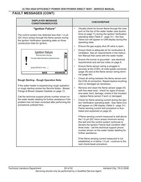
ULTRA HIGH EFFICIENCY POWER VENT/POWER DIRECT VENT - <strong>SERVICE</strong> MANUALFAULT MESSAGES (CONT)DISPLAYED MESSAGECONDITION/INDICATES“Ignition Failure”The control system has detected less than 1.0 μA(DC micro amps) through the flame sensor duringthe Ignition Verification operating state on threeconsecutive trials for ignition.Rough Starting - Rough Operation Note:If the water heater is experiencing rough operationor rough starting review the Service Notes - BlowerFlange & Blower Adapter Gaskets on page 13.Call the technical support phone number shown onthe water heater labeling for further assistance if theproblem has not been corrected after performing theprocedures outlined here.CHECK/REPAIR• Visually check for burner flame through the viewport on the top of the water heater (see illustrationson page 11) during the Ignition Verificationoperating state (Table 5 - page 31) - the GasValve icon will appear on UIM display during thisoperating state.• Ensure the gas supply shut off valve is open.• Ensure there is adequate air for combustion &ventilation. See air requirements in the InstructionManual that came with the water heater.• Ensure the burner is grounded - see electricalrequirements and service notes on page 8.• Ensure flame sensor wiring is plugged insecurely at the CCB’s J4 male spade connector(page 35) and at the flame sensor wiring terminal(page 24).• Check all wiring between the flame sensor andthe CCB J4 connection. Repair/replace anythingworn or damaged as necessary.• Remove and clean the flame sensor (page 24)with fine steel wool - check for signs of excessivewear, bent, damage, cracks in the insulator- replace flame sensor if worn or damaged.• Check for flame sensing current during the IgnitionVerification operating state - Gas Valve iconwill appear on UIM display (Table 5 - page 31).Flame sensing current test procedure is illustratedand explained on page 24.If flame sensing current measured is well abovethe 1.0 μA (DC micro amps) minimum duringthis test and the control system continues todeclare the Ignition Failure fault condition afterthree trials - call the technical support phonenumber shown on the water heater labeling forfurther assistance.If the flame sensing current measured is notestablished or is below 1.0 μA - continue to thenext check/repair procedure.Technical Literature Department 50 of 52 Ashland City, TN © 2008Servicing should only be performed by a Qualified Service Agent


