
You also want an ePaper? Increase the reach of your titles
YUMPU automatically turns print PDFs into web optimized ePapers that Google loves.
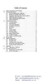
www.obd2express.co.uk<strong>Table</strong> <strong>of</strong> <strong>Contents</strong>1. SAFETY PRECAUTIONS AND WARNINGS .............................................. 12. GENERAL INFORMATION .......................................................................... 22.1 ON-BOARD DIAGNOSTICS (OBD) II ............................................................. 22.2 DIAGNOSTIC TROUBLE CODES (DTCS) ........................................................ 22.3 LOCATION OF THE DATA LINK CONNECTOR (DLC) .................................... 32.4 OBD II READINESS MONITORS .................................................................... 42.5 OBD II MONITOR READINESS STATUS ......................................................... 52.6 OBD II DEFINITIONS .................................................................................... 62.7 OBD II MODES OF OPERATION .................................................................... 73. USING THE SCAN TOOL ............................................................................ 103.1 TOOL DESCRIPTION .................................................................................... 103.2 SPECIFICATIONS .......................................................................................... 113.3 ACCESSORIES INCLUDED............................................................................. 123.4 KEYBOARD .................................................................................................. 123.5 POWER ........................................................................................................ 123.6 SYSTEM SETUP ............................................................................................ 133.7 VEHICLE COVERAGE .................................................................................. 173.8 PRODUCT TROUBLESHOOTING.................................................................... 184. PLAYBACK DATA ....................................................................................... 204.1 REVIEWING DATA ....................................................................................... 204.2 DELETING DATA .......................................................................................... 214.3 PRINTING DATA ........................................................................................... 215. OBDII DIAGNOSTICS ................................................................................. 225.1 READ CODES ............................................................................................... 235.2 ERASING CODES .......................................................................................... 265.3 LIVE DATA .................................................................................................. 285.4 FREEZE FRAME ........................................................................................... 345.5 RETRIEVING I/M READINESS STATUS ......................................................... 355.6 O2 MONITOR TEST ..................................................................................... 385.7 ON-BOARD MONITOR TEST ........................................................................ 395.8 COMPONENT TEST ...................................................................................... 425.9 VIEWING VEHICLE INFORMATION .............................................................. 445.10 MODULES PRESENT .................................................................................... 455.11 DTC LOOKUP ............................................................................................. 466. ABSSRS TESTING ........................................................................................ 486.1 ABSSRS DIAGNOSTIC TESTING ................................................................... 497. PRINT AND UPDATE................................................................................... 587.1 PRINT DATA ................................................................................................ 587.2 SOFTWARE UPDATE .................................................................................... 598. WARRANTY AND SERVICE ...................................................................... 658.1 LIMITED ONE YEAR WARRANTY ................................................................ 658.2 SERVICE PROCEDURES ................................................................................ 65
www.obd2express.co.uk2. General Information2.1 On-Board Diagnostics (OBD) IIThe first generation <strong>of</strong> On-Board Diagnostics (called OBD I) wasdeveloped by the California Air Resources Board (ARB) andimplemented in 1988 to monitor some <strong>of</strong> the emission controlcomponents on vehicles. As technology evolved and the desire toimprove the On-Board Diagnostic system increased, a new generation<strong>of</strong> On-Board Diagnostic system was developed. This second generation<strong>of</strong> On-Board Diagnostic regulations is called "OBD II".The OBD II system is designed to monitor emission control systemsand key engine components by performing either continuous orperiodic tests <strong>of</strong> specific components and vehicle conditions. When aproblem is detected, the OBD II system turns on a warning lamp (MIL)on the vehicle instrument panel to alert the driver typically by thephrase <strong>of</strong> “Check Engine” or “Service Engine Soon”. The system willalso store important information about the detected malfunction sothat a technician can accurately find and fix the problem. Here belowfollow three pieces <strong>of</strong> such valuable information:1) Whether the Malfunction Indicator Light (MIL) iscommanded 'on' or '<strong>of</strong>f';2) Which, if any, Diagnostic Trouble Codes (DTCs) are stored;3) Readiness Monitor status.2.2 Diagnostic Trouble Codes (DTCs)OBD II Diagnostic Trouble Codes are codes that are stored by the on-boardcomputer <strong>diagnostic</strong> system in response to a problem found in the vehicle.These codes identify a particular problem area and are intended to provideyou with a guide as to where a fault might be occurring within a vehicle.OBD II Diagnostic Trouble Codes consists <strong>of</strong> a five-digit alphanumericcode. The first character, a letter, identifies which control system sets thecode. The other four characters, all numbers, provide additionalinformation on where the DTC originated and the operating conditions thatcaused it to set. Here below is an example to illustrate the structure <strong>of</strong> thedigits:2
www.obd2express.co.uk2.3 Location <strong>of</strong> the Data Link Connector (DLC)The DLC (Data Link Connector or Diagnostic Link Connector) is thestandardized 16-cavity connector where <strong>diagnostic</strong> scan <strong>tool</strong>sinterface with the vehicle's on-board computer. The DLC is usuallylocated 12 inches from the center <strong>of</strong> the instrument panel (dash),under or around the driver’s side for most vehicles. If Data LinkConnector is not located under dashboard, a label should be theretelling location. For some Asian and European vehicles, the DLC islocated behind the ashtray and the ashtray must be removed to accessthe connector. If the DLC cannot be found, refer to the vehicle’sservice manual for the location.3
www.obd2express.co.uk2.4 OBD II Readiness MonitorsAn important part <strong>of</strong> a vehicle’s OBD II system is the ReadinessMonitors, which are indicators used to find out if all <strong>of</strong> the emissionscomponents have been evaluated by the OBD II system. They arerunning periodic tests on specific systems and components to ensurethat they are performing within allowable limits.Currently, there are eleven OBD II Readiness Monitors (or I/MMonitors) defined by the U.S. Environmental Protection Agency(EPA). Not all monitors are supported by all vehicles and the exactnumber <strong>of</strong> monitors in any vehicle depends on the motor vehiclemanufacturer’s emissions control strategy.Continuous Monitors -- Some <strong>of</strong> the vehicle components or systemsare continuously tested by the vehicle’s OBD II system, while othersare tested only under specific vehicle operating conditions. Thecontinuously monitored components listed below are always ready:1)Misfire2)Fuel System3)Comprehensive Components (CCM)Once the vehicle is running, the OBD II system is continuouslychecking the above components, monitoring key engine sensors,watching for engine misfire, and monitoring fuel demands.Non-Continuous Monitors -- Unlike the continuous monitors, manyemissions and engine system components require the vehicle to beoperated under specific conditions before the monitor is ready. Thesemonitors are termed non-continuous monitors. For different ignitiontype engines, the available monitors are different too.4
www.obd2express.co.ukThe following monitors are to be used for spark ignition enginesonly:1) EGR System2) O2 Sensors3) Catalyst4) Evaporative System5) O2 Sensor Heater6) Secondary air7) Heated CatalystThe following monitors are to be used for compression ignitionengines only:1) EGR System2) NMHC Catalyst3) NOx aftertreatment4) Boost pressure system5) Exhaust gas sensor6) PM filter2.5 OBD II Monitor Readiness StatusOBD II systems must indicate whether or not the vehicle’s PCM’smonitor system has completed testing on each component.Components that have been tested will be reported as “Ready”, or“Complete”, meaning they have been tested by the OBD II system.The purpose <strong>of</strong> recording readiness status is to allow inspectors todetermine if the vehicle’s OBD II system has tested all thecomponents and/or systems.The power-train control module (PCM) sets a monitor to “Ready” or“Complete” after an appropriate drive cycle has been performed. Thedrive cycle that enables a monitor and sets readiness codes to “Ready”varies for each individual monitor. Once a monitor is set as “Ready”or “Complete”, it will remain in this state. A number <strong>of</strong> factors,including erasing <strong>of</strong> <strong>diagnostic</strong> trouble codes (DTCs) with a scan <strong>tool</strong>or a disconnected battery, can result in Readiness Monitors being set5
www.obd2express.co.ukto “Not Ready”. Since the three continuous monitors are constantlyevaluating, they will be reported as “Ready” all <strong>of</strong> the time. If testing<strong>of</strong> a particular supported non-continuous monitor has not beencompleted, the monitor status will be reported as “Not Complete” or“Not Ready.”In order for the OBD monitor system to become ready, the vehicleshould be driven under a variety <strong>of</strong> normal operating conditions.These operating conditions may include a mix <strong>of</strong> highway driving andstop and go, city type driving, and at least one overnight-<strong>of</strong>f period.For specific information on getting your vehicle’s OBD monitorsystem ready, please consult your vehicle owner’s manual.2.6 OBD II DefinitionsPower-train Control Module (PCM) -- OBD II terminology for theon-board computer that controls engine and drive train.Malfunction Indicator Light (MIL) -- Malfunction Indicator Light(Service Engine Soon, Check Engine) is a term used for the light onthe instrument panel. It is to alert the driver and/or the repairtechnician that there is a problem with one or more <strong>of</strong> vehicle'ssystems and may cause emissions to exceed federal standards. If theMIL illuminates with a steady light, it indicates that a problem hasbeen detected and the vehicle should be serviced as soon as possible.Under certain conditions, the dashboard light will blink or flash. Thisindicates a severe problem and flashing is intended to discouragevehicle operation. The vehicle onboard <strong>diagnostic</strong> system cannot turnthe MIL <strong>of</strong>f until necessary repairs are completed or the condition nolonger exists.DTC -- Diagnostic Trouble Codes (DTC) that identify which section<strong>of</strong> the emission control system has malfunctioned.Enabling Criteria -- Also termed Enabling Conditions. They are thevehicle-specific events or conditions that must occur within theengine before the various monitors will set, or run. Some monitorsrequire the vehicle to follow a prescribed “drive cycle” routine as part<strong>of</strong> the enabling criteria. Drive cycles vary among vehicles and foreach monitor in any particular vehicle.6
www.obd2express.co.ukOBD II Drive Cycle -- A specific mode <strong>of</strong> vehicle operation thatprovides conditions required to set all the readiness monitorsapplicable to the vehicle to the “ready” condition. The purpose <strong>of</strong>completing an OBD II drive cycle is to force the vehicle to run itsonboard <strong>diagnostic</strong>s. Some form <strong>of</strong> a drive cycle needs to beperformed after DTCs have been erased from the PCM’s memory orafter the battery has been disconnected. Running through a vehicle’scomplete drive cycle will “set” the readiness monitors so that futurefaults can be detected. Drive cycles vary depending on the vehicle andthe monitor that needs to be reset. For vehicle specific drive cycle,consult the vehicle’s Owner’s Manual.Freeze Frame Data -- When an emissions related fault occurs, theOBD II system not only sets a code but also records a snapshot <strong>of</strong> thevehicle operating parameters to help in identifying the problem. Thisset <strong>of</strong> values is referred to as Freeze Frame Data and may includeimportant engine parameters such as engine RPM, vehicle speed, airflow, engine load, fuel pressure, fuel trim value, engine coolanttemperature, ignition timing advance, or closed loop status.2.7 OBD II Modes <strong>of</strong> OperationHere is a basic introduction to the OBD II communication protocol.Mode byte: The first byte in the stream is the mode number. Thereare 10 modes for <strong>diagnostic</strong> requests. The first byte in the responsedata bytes is this same number plus 64. For example, a mode 1request would have the first data byte = 1, and the response wouldhave the first data byte = 65. Here is a brief description <strong>of</strong> the modes:Mode $01 – Identifies the Power-train information and showscurrent data available to the scan <strong>tool</strong>. This data includes: DTC set,status <strong>of</strong> on-board tests, and vehicle data such as engine RPM,temperatures, ignition advance, speed, air flow rates, and closed loopstatus for fuel system.Mode $02 – Displays Freeze Frame data. Same data as in mode 1,but it was captured and stored when a malfunction occurred and aDTC was set. Some <strong>of</strong> the PIDs for mode one are not implemented inthis mode.7
www.obd2express.co.ukMode $03 – Displays the type <strong>of</strong> power-train or emission relatedDTCs stored by a 5 digit code identifying the faults. There may bemore than one response message if there are more trouble codes thanwill fit in the data bytes <strong>of</strong> the response message, or if there are morethan one ECU computer responding.Mode $04 – Used to clear DTCs and Freeze Frame data. Thisclears all <strong>diagnostic</strong> trouble codes that may be set including freezeframe data and readiness monitors.Mode $05 – Oxygen Sensor Test Results. This mode displays theoxygen sensor monitor screen and the test results gathered about theoxygen sensor.There are ten numbers available for <strong>diagnostic</strong>s:1. $01 Rich-to-Lean O2 sensor threshold voltage.2. $02 Lean-to-Rich O2 sensor threshold voltage.3. $03 Low sensor voltage threshold for switch timemeasurement.4. $04 High sensor voltage threshold for switch timemeasurement.5. $05 Rich-to-Lean switch time in ms.6. $06 Lean-to-Rich switch time in ms.7. $07 Minimum voltage for test.8. $08 Maximum voltage for test.9. $09 Time between voltage transitions in ms.Mode $06 – Non-continuously Monitored Systems test results.There are typically a minimum value, a maximum value, and acurrent value for each non-continuous monitor. This data is optional,and it is defined by a given vehicle maker if it’s used.Mode $07 – Request for DTCs (pending) from ContinuouslyMonitored Systems after a single driving cycle has beenperformed to determine if repair has fixed a problem. This usedby service technicians to verify repair was performed properly andafter clearing <strong>diagnostic</strong> trouble codes.8
www.obd2express.co.ukMode $08 – This special Control Mode requests control <strong>of</strong> theon-board system, test, or component bi-directionally (whereapplicable). This mode is manufacturer specific.Mode $09 – Reports vehicle information. This informationincludes vehicle VIN number and calibration information stored inthe vehicle ECUs.Mode $0A – Request Emission-Related Diagnostic TroubleCodes with Permanent Status. This mode is required for allemissions-related DTCs. The presence <strong>of</strong> permanent DTCs at aninspection without the MIL illuminated is an indication that a properrepair was not verified by the on-board monitoring system.9
www.obd2express.co.uk3. Using the Scan Tool3.1 Tool Description1) OBD II CONNECTOR – Connects the scan <strong>tool</strong> to thevehicle’s Data Link Connector (DLC).2) LCD DISPLAY – Indicates test results.3) FUNCTION BUTTONS – Corresponds with “buttons” onscreen for executing commands.4) ESC BUTTON – Cancels a selection (or action) from amenu or returns to the previous screen.10
www.obd2express.co.uk5) LEFT SCROLL BUTTON – When look up DTCdefinitions, moves to previous character and views additionalinformation on previous screens if DTC definition covers morethan one screen; views previous screen or previous frames <strong>of</strong>recorded data. It is also used to view previous trouble codewhen viewing DTCs.6) HELP BUTTON – Provides help information and CodeBreaker function.7) DOWN SCROLL BUTTON –Moves down throughmenu and submenu items in menu mode. When more than onescreen <strong>of</strong> data is retrieved, moves down through the currentscreen to next screens for additional data. When looking up DTC,it is used to change value <strong>of</strong> selected character.8) RIGHT SCROLL BUTTON – When look up DTCdefinitions, moves to next character and view additionalinformation on next screens if DTC definition covers more thanone screen; views next screen or next frames <strong>of</strong> recorded data. Itis also used to view next trouble code when viewing DTCs.9) OK BUTTON – Confirms a selection (or action) from amenu.10) UP SCROLL BUTTON – Moves up through menu andsubmenu items in menu mode. When more than one screen <strong>of</strong>data is retrieved, moves up through the current screen to theprevious screens for additional data. When looking up DTC, it isused to change value <strong>of</strong> selected character.11) USB CONNECTOR – Connects the scan <strong>tool</strong> to the PC forprinting.12) TF CARD SLOT – Holds the TF card.3.2 Specifications1) Display: TFT color display (320 x 240 dpi)2) Operating Temperature: 0 to 60°C (32 to 140 F°)11
www.obd2express.co.uk3) Storage Temperature: -20 to 70°C (-4 to 158 F°)4) External Power: 8.0 to 18.0 V power provided via vehiclebattery5) Dimensions:Length Width Height199 mm (7.83”) 104.5 mm (4.11”) 37.5 mm (1.48”)6) Weight: 0.28kg(without wire) 0.484kg(with wire)3.3 Accessories Included1) User’s Manual -- Instructions on <strong>tool</strong> operations.2) CD -- Includes user’s manual, MaxiLink update s<strong>of</strong>tware, andetc.3) OBDII cable -- Provides power to <strong>tool</strong> and communicatesbetween <strong>tool</strong> and vehicle.4) USB cable -- Used to print retrieved data.5) Protective Nylon Case – A nylon case to store the <strong>tool</strong> whennot in use.6) TF card -- Used to store data and to upgrade the scan <strong>tool</strong>3.4 KeyboardNo solvents such as alcohol are allowed to clean the keypad or display.Use a mild nonabrasive detergent and a s<strong>of</strong>t cotton cloth. Do not soakthe keypad as the keypad is not waterpro<strong>of</strong>.3.5 PowerThe scan <strong>tool</strong> is powered via the vehicle Data Link Connector (DLC).Just follow the steps below to turn on the scan <strong>tool</strong>:1) Connect the OBD II Cable to scan <strong>tool</strong>.2) Find DLC on vehicle.A plastic DLC cover may be found for some vehicles and youneed to remove it before plugging the OBDII cable.3) Plug OBD II cable to the vehicle’s DLC.12
www.obd2express.co.uk4) Power up the scan <strong>tool</strong> , and wait for the Main Screen toappear.(Figure 3.1)3.6 System SetupFigure 3.1The System Setup functions allow you to adjust default settings andview information about the scan <strong>tool</strong>.1) Language: Selects the desired language.2) Unit <strong>of</strong> measure: Sets the unit <strong>of</strong> measure to English or Metric.3) Beep Set: Turns on/<strong>of</strong>f beep.4) Key Test: Checks if the keyboard is working properly.5) LCD Test: Checks if the LCD display is working properly.6) About: Provides information <strong>of</strong> the scan <strong>tool</strong>.Settings <strong>of</strong> the unit will remain until change to the existingsettings is made.To enter the Setup menuFrom the Main Screen: Use LEFT/RIGHT scroll button to selectSetup, and press the OK button. Following the instructions to doadjustments and settings could make your diagnosis moreconveniently and easily. (Figure 3.2)13
www.obd2express.co.ukLanguage SetupFigure 3.2 English is the default language.1) From System Setup screen, use the UP/DOWN scroll buttonand LEFT/RIGHT scroll button to select Language, and pressthe OK button.2) Use the UP/DOWN scroll button to select the desired languageand press the OK button to save your selection and return toprevious screen. (Figure 3.3)Unit <strong>of</strong> MeasureFigure 3.3 Metric is the default measurement unit.1) From System Setup screen, use the LEFT/RIGHT scroll buttonto select EN/METRIC and press the OK button.14
www.obd2express.co.uk2) From Unit <strong>of</strong> Measure screen, use the LEFT/RIGHT scrollbutton to select the desired unit <strong>of</strong> measurement. (Figure 3.4 )Figure 3.43) Press the OK button to save your selection and return to previousmenu. Or, press the ESC button to exit without saving.Beep Set The default setting is Beep On.1) From System Setup screen, use the UP/DOWN scroll buttonand LEFT/RIGHT scroll button to select Beep and press theOK button.2) From Beep Set menu, use the LEFT/RIGHT scroll button toselect ON or OFF to turn on/<strong>of</strong>f the beep. (Figure 3.5)Figure 3.515
www.obd2express.co.uk3) Press the OK button to save your selection and return toprevious menu. Or, press the ESC button to exit without saving.Key TestThe Key Test function checks if the keyboard is working properly.1) From System Setup screen, use the UP/DOWN scroll buttonand LEFT/RIGHT scroll button to select Key Test, and pressthe OK button.2) Press any key to start test. When you press a key, the edge aroundcorresponding key on the screen should turn to red. Otherwise,the key is not functioning properly. (Figure 3.6)Figure 3.63) Double press ESC to return to previous menu.LCD TestThe LCD Test function checks if the LCD display is workingnormally.1) From System Setup screen, use the UP/DOWN scroll buttonand LEFT/RIGHT scroll button to select LCD Test, and pressthe OK button.2) Look for missing spots in the red, green, blue, black and whiteLCD display.16
www.obd2express.co.uk3) When completed, press the ESC button to exit.AboutThe About function allows viewing <strong>of</strong> some important informationsuch as serial number and s<strong>of</strong>tware version number <strong>of</strong> the scanner.1) From System Setup screen, use the UP/DOWN scroll buttonand LEFT/RIGHT scroll button to select About and press theOK button, wait for the About screen to appear.2) View <strong>tool</strong> information on screen. (Figure 3.7) Press the ESCbutton to exit without saving.3.7 Vehicle CoverageFigure 3.7The AutoLink AL619 OBDII/EOBD Scanner is specially designedto work with all OBD II compliant vehicles, including those equippedwith next-generation protocol -- Control Area Network (CAN). It isrequired by EPA that all 1996 and newer vehicles (cars and lighttrucks) sold in the United States must be OBD II compliant and thisincludes all Domestic, Asian and European vehicles.A small number <strong>of</strong> 1994 and 1995 model year gasoline vehicles areOBD II compliant. To verify if a 1994 or 1995 vehicle is OBD IIcompliant, check the Vehicle Emissions Control Information (VECI)Label which is located under the hood or by the radiator <strong>of</strong> mostvehicles. If the vehicle is OBD II compliant, the label will designate17
www.obd2express.co.uk“OBD II Certified”. Additionally, Government regulations mandatethat all OBD II compliant vehicles must have a “common”sixteen-pin Data Link Connector (DLC).For your vehicle to be OBD II compliant it must have a 16-pin DLC(Data Link Connector) under the dash and the Vehicle EmissionControl Information Label must state that the vehicle is OBD IIcompliant.In addition to OBD II diagnosis, the AL609 scan <strong>tool</strong> also supportsthe ABS <strong>diagnostic</strong> function, dealing with more than 20 US, Asianand European vehicles, including GM, Ford, Chrysler, Volvo, VW,BMW, Benz, Smart, Sprinter, Toyota, Honda, Nissan, Hyundai, Kia,Subaru, Mitsubishi, Peugeot, Citroen, (Peugeot and Citroen are onlyfor AL619EU) Fiat, Renault, Landrover, Jaguar.More vehicle supports will come out with new updates released.3.8 Product TroubleshootingThis part describes problems that you may encounter while using thescan <strong>tool</strong>.Vehicle Linking ErrorA communication error occurs if the scan <strong>tool</strong> fails to communicatewith the vehicle’s ECU (Engine Control Unit). You need to do thefollowing to check up: Verify that the ignition is ON. Check if the scan <strong>tool</strong>’s OBD II connector is securelyconnected to the vehicle’s DLC. Verify that the vehicle is OBDII compliant. Turn the ignition <strong>of</strong>f and wait for about 10 seconds. Turn theignition back to on and continue the testing. Verify the control module is not defective.Operating Error18
www.obd2express.co.ukIf the scan <strong>tool</strong> freezes, then an exception occurs or the vehicle’sECU (Engine Control Unit) is too slow to respond to requests. Youneed to do the following to reset the <strong>tool</strong>: Reset the scan <strong>tool</strong>. Turn the ignition <strong>of</strong>f and wait for about 10 seconds. Turn theignition back to on and continue the testing.Scan <strong>tool</strong> doesn’t power upIf the scan <strong>tool</strong> won’t power up or operates incorrectly in any otherway, you need to do the following to check up: Check if the scan <strong>tool</strong>’s OBD II connector is securely connectedto the vehicle’s DLC; Check if the DLC pins are bent or broken. Clean the DLC pins ifnecessary. Check vehicle battery to make sure it is still good with at least 8.0volts.19
www.obd2express.co.uk4. Playback DataThe Playback Data function allows viewing data from last testrecorded by the scan <strong>tool</strong>.4.1 Reviewing Data1) Use the LEFT/RIGHT scroll button to select Playback fromMain Screen (Figure 3.1), and press the OK button. Wait forthe Review Data screen to appear.1.AbsSrs2.ScanReview DataFigure 4.12) To review data saved in the scan function, select Scan in theReplay menu. To review data saved in the AbsSrs function,select AbsSrs in the Replay menu. Then press OK button tocontinue.3) Use the UP/DOWN scroll button to select the desired DTCentries from Scan menu or AbsSrs menu (Figure 4.2), and pressthe OK button.AbsSrs1. Trouble Code/scan/ABSSRS/USA/GM/savedDeleteDelete AllFigure 4.220
www.obd2express.co.ukIf no data from previously tested vehicle is recorded, a message“No data available!” shows on the screen.Review selected data on screen.4.2 Deleting DataFigure 4.3By selecting Delete on the AbsSrs screen (Figure 4.2), you areallowed to erase the selected data on the scan <strong>tool</strong>. Review therecordings thoroughly before erasing. You could also erase allrecordings by select Delete All.NOTE: Don’t use Delete All unless you are definitely sure whatyou are going to proceed.4.3 Printing DataVehicle SpecificationVehicle: MustangEngine Type: OtherCapacity: 3.8LTransmission: ManualFuel Type: GasolineEmission Level: Federal EmissionVIN:1FAFP40462F100819PrefSuf:2R3APB VersionID:4612PrintPrint option allows you to print the recorded files to your computerand then to the printer.For more details, please refer to chapter 7.1 Print Data.21
www.obd2express.co.uk5. OBDII DiagnosticsThe OBD II Diagnostics function is a fast-access option that allowsyou to carry out a quick test on the engine system <strong>of</strong> OBD IIvehicles.When more than one vehicle control module is detected by thescan <strong>tool</strong>, you will be prompted to select the module where thedata may be retrieved. The most <strong>of</strong>ten to be selected are thePower-train Control Module [PCM] and Transmission ControlModule [TCM].CAUTION: Don’t connect or disconnect any test equipment withignition on or engine running.1) Turn the ignition <strong>of</strong>f.2) Locate the vehicle’s 16-pin Data Link Connector (DLC).3) Plug the scan <strong>tool</strong> cable connector into the vehicle’s DLC.4) Turn the ignition on. Engine can be <strong>of</strong>f or running.5) Turn on the scan <strong>tool</strong>. Select OBDII from the Main Screen.(Figure 3.1)6) Press the OK button to wait for the Menu to appear. A sequence<strong>of</strong> messages displaying the OBDII protocols will be observedon the display until the vehicle protocol is detected.If the scan <strong>tool</strong> fails to communicate with the vehicle’s ECU(Engine Control Unit) more than three times, a “LINKINGERROR!” message shows up on the display.Verify that the ignition is ON.Check if the scan <strong>tool</strong>’s OBD II connector is securelyconnected to the vehicle’s DLC.Verify that the vehicle is OBD2 compliant.Turn the ignition <strong>of</strong>f and wait for about 10 seconds. Turn theignition back to on and repeat the procedure from step 5.If the “LINKING ERROR” message does not go away, thenthere might be problems for the scan <strong>tool</strong> to communicate with22
www.obd2express.co.ukthe vehicle. Contact your local distributor or themanufacturer’s customer service department for assistance.7) View a summary <strong>of</strong> system status (MIL status, DTC counts,Monitor status) on screen. (Figure 5.1 ) Press ESC button forDiagnostic Menu (Figure 5.3) to come up.System StatusMIL Status OFFCodes Found 0Monitors N/A 8Monitors OK 2Monitors INC 0SaveOKFigure 5.1If more than one module is detected, you will be prompted toselect a module before testing. (Figure 5.2 )Module $10Module $A4Control ModuleFigure 5.2 Use the UP/DOWN scroll button to select a module and pressthe OK button.5.1 Read Codes Reading Codes can be done with the key on engine <strong>of</strong>f (KOEO)or with the key on engine running (KOER). Stored Codes are also known as “hard codes”, which are faultcodes, or trouble codes that have been stored in the vehiclecomputer memory because the faults have reoccurred for23
www.obd2express.co.ukmore than a specified amount <strong>of</strong> key-cycles. These codes willcause the control module to illuminate the malfunctionindicator light (MIL) when emission-related fault occurs. Pending Codes are also referred to as “maturing codes” or“continuous monitor codes”. They indicate problems that thecontrol module has detected during the current or last drivingcycle but are not considered serious yet. Pending Codes willnot turn on the malfunction indicator lamp (MIL). If the faultdoes not occur within a certain number <strong>of</strong> warm-up cycles, thecode clears from memory. Permanent Codes are DTCs that are "confirmed" and areretained in the non-volatile memory <strong>of</strong> the computer until theappropriate monitor for each DTC has determined that themalfunction is no longer present and is not commanding theMIL on. Permanent DTC shall be stored in non-volatilememory and may not be erased by any <strong>diagnostic</strong> services orby disconnecting power to ECU.1) Use UP/DOWN scroll button to select Read Codes fromDiagnostic Menu and press OK button. (Figure 5.3 )Diagnostic Menu1.System Status2.Read Codes3.Erase Codes4.Live Data5.Freeze Frame6.I/M Readiness7.O2 Monitor Test8.On-Board Monitor TestFigure 5.32) Use the UP/DOWN scroll button to select Stored Codes,Pending Codes or Permanent Codes from the Read Codesmenu and press the OK button. (Figure 5.4 )24
www.obd2express.co.ukRead Codes1.Stored Codes2.Pending Codes3.Permanent CodesFigure 5.4If there is not any Diagnostic Trouble Code, the display indicates“No (pending) codes are stored in the module!” Wait a fewseconds or press any key to return to previous screen.NOTE: Permanent Codes function is available for merelyvehicles supporting the CAN protocols.3) View DTCs and their definitions on screen.4) If more than one DTC is found, use the UP/DOWN scrollbutton to check all the codes.If retrieved DTCs contain any manufacturer specific or enhancedcodes, a “Manufacturer specific codes are found! Press any keyto select vehicle make!” message comes up prompting you toselect vehicle manufacturer to view DTC definitions. UseUP/DOWN scroll button to select manufacturer and then pressOK button to confirm.Vehicle ManufacturerBUICKBMWCADILLACCHEVROLETCHRYSLERFORDFigure 5.525
www.obd2express.co.ukIf the manufacturer <strong>of</strong> your vehicle is not listed, use theUP/DOWN scroll button to select Other and press the OKbutton.5.2 Erase CodesCAUTION: Erasing the Diagnostic Trouble Codes may allow thescan <strong>tool</strong> to delete not only the codes from the vehicle’s on-boardcomputer, but also “Freeze Frame” data and manufacturerspecific enhanced data. Further, the I/M Readiness Monitor Statusfor all vehicle monitors is reset to Not Ready or Not Completestatus. Do not erase the codes before the system has been checkedcompletely by a technician.NOTE: Erasing codes does not mean that trouble codes inECU have been eliminated completely. As long as there isfault with the vehicle, the trouble codes keeps on presenting. This function is performed with key on engine <strong>of</strong>f (KOEO). Donot start the engine.1) Use the UP/DOWN scroll buttons to select Erase Codes fromDiagnostics Menu and press the OK button. (Figure 5.3)2) After you have pressed OK button, a message will come upasking you to check the ignition and engine status. (Figure 5.6)Erase CodesIgnition on and engine stopped?Yes No .Figure 5.6• If you do not want to proceed with erasing codes, press ESCbutton or select NO to exit and return to previous screen.26
www.obd2express.co.uk• If you press Yes function key or OK button, a warning messagewill come up asking your confirmation. (Figure 5.7)Erase CodesDTCs and Freeze Data will be lostDo you wish to continue?Yes No .Figure 5.73) Press the OK button to confirm.If the codes are cleared successfully, an “Erase Done!”confirmation message shows on the display.( Figure 5.8)Erase CodesErase Done!Press any key to continue .Figure 5.8If the codes are not cleared, then an “Erase Failure. Turn Keyon with Engine <strong>of</strong>f!” message appears. (Figure 5.9)Erase CodesErase Failure.Turn Key on withEngine Off!Press any key to continueFigure 5.927
www.obd2express.co.uk4) Press any button to return to Diagnostic Menu.5.3 Live DataIn this function, you can not only read the live data but also recorddata for later review.Viewing DataThe View Data function allows viewing <strong>of</strong> live or real time PIDdata <strong>of</strong> vehicle’s computer module(s).1) To view live data, use the UP/DOWN scroll button to select LiveData from Diagnostic Menu and press the OK button. (Figure5.3)2) Wait a few seconds while the scan <strong>tool</strong> validates the PID MAP.(Figure 5.10)Live DataReading PID.01- Please Wait -A. Viewing Complete ListFigure 5.101) To view complete set <strong>of</strong> data, use UP/DOWN scroll button toselect Complete List from Live Data menu and press the OKbutton. (Figure 5.11)28
www.obd2express.co.uk…………………Live Data .1. Complete List2. Custom ListFigure 5.112) View live PIDs on the screen. Use the UP/DOWN scroll buttonfor more PIDs if additional information is available on more thanone page.( Figure 5.12)Complete ListNumbers <strong>of</strong> DTCs 0Fuel system 1 status OLFuel system 2 status --Calculated load value 0.0 %Engine coolanttemperature-400 CPause Graphics SaveFigure 5.12If the “Graphics” on the bottom appears when a PID ishighlighted, graphic information is available. SelectGraphics to view graph. (Figure 5.13). PID name, currentvalue, maximum and minimum values are displayed on thescreen.29
www.obd2express.co.ukFigure 5.13If the “Merge Graph” on the bottom appears when a PID isselected to view, merged graph information is available.(Figure 5.14)NOTE: Merge Graph can be used to compare two relatedparameters in graphic mode, which is especially convenient inthe Custom List option where you could select two interactedparameter to merge and see their relationship.Figure 5.14Select Text to return to text viewing <strong>of</strong> PID data.Select Save to record retrieved live data and PID graphs.Select Pause to suspend viewing. You could resume theviewing process again by selecting Start.30
www.obd2express.co.uk3) Press the ESC button to return to previous menu.B. Viewing Custom List1) To view customized PID data, use the UP/DOWN scroll button toselect Custom List from Live Data menu and press the OKbutton.( Figure 5.11)2) Use the UP/DOWN scroll button to move up and down to thedesired items and click Select button to confirm. The selectedparameters are marked with solid squares.( Figure 5.15 )………… ..CustomFigure 5.15List Numbers <strong>of</strong> DTCs 1 Fuel system 1 status 2 Fuel system 2 status Calculated load value Engine coolant tempSelect All Clear Clear allThe number to the right <strong>of</strong> selected item indicates sequence<strong>of</strong> this item.If you want to deselect the item, press Clear button.To select all the items on the screen, press Select All button.To clear all the selected items on the screen, press Clear Allbutton.3) Press the OK button to view selected PIDs on screen.31
www.obd2express.co.ukCustomListNumbers <strong>of</strong> DTCs 0Fuel system 1 status OLFigure 5.164) Use the ESC button to return to previous menu.Recording DataPause Graphics SaveThe Record Data function allows recording vehicle modules’Parameter Identification (PID) data to help diagnoseintermittent vehicle problems. You could save data files to theSD card and then use the Playback function to view the savedfiles.NOTE: The length <strong>of</strong> time for each frame varies per vehicle.Generally, one frame <strong>of</strong> data is about 1/4 second, or 4 frames persecond.1) To record live data, with the live data screen displaying, selectSave on the bottom. The scan <strong>tool</strong> will start timing to recordretrieved live data and PID graphs.If you record live data under text mode, following screenshows:Complete ListNumbers <strong>of</strong> DTCs 0Fuel system 1 status OLFuel system 2 status --Calculated load value 0.0 %Engine coolanttemperature-400 CPause Graphics Saving 94Figure 5.1732
www.obd2express.co.ukIf you record live data under graph mode, following screenshows:Figure 5.18NOTE: The scan <strong>tool</strong> can only playback text data eventhough the data is saved in graphic mode.2) When there is not enough memory space, a warning messageprompting to delete previously recorded data.Save FailureMemory space not enough!Erase previously recordedData?YesNoFigure 5.19If you wish to delete the data, select Yes and save currentlyretrieved data in the SD card.If you do not wish to delete the data, select No to return toprevious screen.3) Select Pause to suspend recording. You could resume therecording process again by selecting Start.33
www.obd2express.co.uk4) You may review the saved data in Playback function.5) Press ESC button to exit.5.4 Freeze FrameFreeze Frame Data allows the technician to view the vehicle’soperating parameters at the moment a DTC (Diagnostic TroubleCode) is detected. For example, the parameters may includeengine speed (RPM), engine coolant temperature (ECT), orvehicle speed sensor (VSS) etc. This information will aid thetechnician by allowing the parameters to be duplicated for<strong>diagnostic</strong> and repair purposes.1) To view freeze frame data, use the UP/DOWN scroll button toselect Freeze Frame from Diagnostic Menu and press the OKbutton. (Figure 5.3 )2) Wait a few seconds while the scan <strong>tool</strong> validates the PID MAP.3) If retrieved information covers more than one screen, use theDOWN scroll button, as necessary, until all the data have beenshown up. (Figure 5.20)Freeze FrameDTC that caused required P0193freeze frame data storageFuel system 1 statusOLFuel system 2 status --Calculated load value 0.0 %Engine coolanttemperature-400 CSaveFigure 5.20• If there is no available freeze frame data, an advisory message“No freeze frame data stored!” shows on the display.4) Select Save to record freeze frame. A confirming message “Savesuccess!” shows on the display and scan <strong>tool</strong> return to previousmenu.34
www.obd2express.co.uk5) If you don’t want to save the freeze frame data, press ESCbutton to return to previous screen.5.5 Retrieving I/M Readiness StatusI/M Readiness function is used to check the operations <strong>of</strong> theEmission System on OBD2 compliant vehicles. It is an excellentfunction to use prior to having a vehicle inspected forcompliance to a state emissions program.CAUTION - By clearing trouble codes you also clear the readinessstatus for the individual emission system readiness tests. In orderto reset these monitors, the vehicle must be driven through acomplete drive cycle with no trouble codes in memory. Times forreset vary depending on vehicle.Some latest vehicle models may support two types <strong>of</strong> I/MReadiness tests:A. Since DTCs Cleared - indicates status <strong>of</strong> the monitors since theDTCs are erased.B. This Drive Cycle - indicates status <strong>of</strong> monitors since thebeginning <strong>of</strong> the current drive cycle.An I/M Readiness Status result <strong>of</strong> “NO” does not necessarilyindicate that the vehicle being tested will fail the state I/Minspection. For some states, one or more such monitors may beallowed to be “Not Ready” to pass the emissions inspection.• “OK” -- Indicates that a particular monitor being checked hascompleted its <strong>diagnostic</strong> testing.• “INC” -- Indicates that a particular monitor being checked hasnot completed its <strong>diagnostic</strong> testing.• “N/A” -- The monitor is not supported on that vehicle.1) Use the UP/DOWN scroll button to select I/M Readiness fromDiagnostic Menu and press OK button. (Figure 5.3)2) Wait a few seconds while the scan <strong>tool</strong> validates the PID MAP.35
www.obd2express.co.uk3) If the vehicle supports both types <strong>of</strong> tests, then both types will beshown on the screen for selection. (Figure 5.21)…………… I/M Readiness .1.Since DTCs Cleared2.This Drive CycleFigure 5.214) Use the UP/DOWN scroll button, as necessary, to view the status<strong>of</strong> the MIL light (“ON” or “OFF) and the following monitors:For spark ignition engines: MIS -- Misfire Monitor FUEL -- Fuel System Monitor CCM -- Comprehensive Component Monitor EGR – EGR System Monitor O2S -- O2 Sensors Monitor CAT -- Catalyst Monitor EVAP -- Evaporative System Monitor HTR -- O2 Sensor Heater Monitor AIR -- Secondary Air Monitor HCAT -- Heated Catalyst MonitorFor compression ignition engines: MIS -- Misfire Monitor FUEL -- Fuel System Monitor CCM -- Comprehensive Component Monitor EGR – EGR System Monitor HCCAT -- NMHC Catalyst Monitor36
www.obd2express.co.uk NCAT -- NOx Aftertreatment Monitor BP -- Boost Pressure System Monitor EGS -- Exhaust Gas Sensor Monitor PM -- PM Filter MonitorSince DTCs clearedMIL StatusMisfire MonitoringFuel system monitoringComprehensivecomponent monitoringCatalyst monitoringHeated catalyst monitorOFFN/AOKOKN/AN/AFigure 5.225) If the vehicle supports readiness test <strong>of</strong> “This Drive Cycle”, ascreen <strong>of</strong> the following displays: (Figure 5.23)This Drive CycleMIL StatusMisfire MonitoringFuel system monitoringComprehensivecomponent monitoringOFFN/AOKOKFigure 5.23Catalyst monitoringN/AHeated catalyst monitor6) Use the UP/DOWN scroll button for more PIDs if additionalinformation is available on more than one page. Or use theLEFT/RIGHT scroll button to view PIDs in the previous/nextpage.N/A7) Press the ESC button to return to Diagnostic Menu.37
www.obd2express.co.uk5.6 O2 Monitor TestOBD2 regulations set by SAE require that relevant vehiclesmonitor and tests on the oxygen (O2) sensors to identify problemsrelated to fuel efficiency and vehicle emissions. These tests are noton-demand tests and they are done automatically when engineoperating conditions are within specified limits. These test resultsare saved in the on-board computer's memory.The O2 Monitor Test function allows retrieval and viewing <strong>of</strong> O2sensor monitor test results for the most recently performed testsfrom the vehicle's on-board computer.The O2 Monitor Test function is not supported by vehicles whichcommunicate using a controller area network (CAN). For O2Monitor Test results <strong>of</strong> CAN-equipped vehicles, see chapter“On-Board Mon. Test”.1) Use the UP/DOWN scroll button to select O2 Monitor Testfrom Diagnostic Menu and press OK button. (Figure 5.3)2) Wait a few seconds while the scan <strong>tool</strong> validates the PID MAP.3) Use the UP/DOWN scroll button to select O2 sensor from O2Monitor Test menu and press OK button. (Figure 5.24).......... ..O2 Monitor Test …1.O2 Bank1 Sensor12.O2 Bank1 Sensor23.O2 Bank2 Sensor14.O2 Bank2 Sensor2Figure 5.24• If the vehicle does not support the mode, an advisory messagewill be displayed on the screen. (Figure 5.25)38
www.obd2express.co.uk…………….O2 Monitor Test…………..The selected mode isnot supported!Press any key to continue .Figure 5.254) View test results <strong>of</strong> selected O2 sensor. (Figure 5.26)… ……… .O2 Bank1 Sensor2 .Rich-Lean Threshd VLean-Rich Threshd VLow for Switch (V)High for Switch (V)Rich-Lean Threshd SLean-Rich Threshd SFigure 5.265) Use the UP/DOWN scroll button to view more screens <strong>of</strong> data ifadditional information is available in more than one page.6) Press the ESC button to return to the previous menu.5.7 On-Board Monitor TestThe On-Board Monitor Test is useful after servicing or aftererasing a vehicle’s control module memory. The On-BoardMonitor Test for non-CAN-equipped vehicles retrieves anddisplays test results for emission-related power train componentsand systems that are not continuously monitored. The On-BoardMonitor Test for CAN-equipped vehicles retrieves and displaystest results for emission-related power train components andsystems that are and are not continuously monitored. Test andcomponents IDs are determined by the vehicle manufacturer.In this test, there are typically a minimum value, a maximum value,39
www.obd2express.co.ukand a current value for each monitor. By comparing the current valuewith the minimum and maximum value, the scan <strong>tool</strong> will determineif it is OK.1) Use the UP/DOWN scroll button to select On-Board MonitorTest from Diagnostic Menu and press the OK button. (Figure5.3)2) Wait a few seconds while the scan <strong>tool</strong> validates the PID MAP.3) The scan <strong>tool</strong> will prompt you to select the vehicle make. (If youhave selected the vehicle before, the Vehicle Manufacturerscreen would not appear again)Vehicle ManufacturerBUICKBMWCADILLACCHRYSLERFORDGMFigure 5.274) After you select the vehicle manufacturer, the scan <strong>tool</strong> showsthe On-Board Monitors tests for specific monitoring systems.5) From On-Board Monitor Test menu, use the UP/DOWN scrollbutton to select a test to view and press the OK button. (Figure5.28)40
www.obd2express.co.ukOn-Board Monitor Test1. Test $01 Data2. Test $03 Data3. Test $10 Data4. Test $21 Data5. Test $22 Data6. Test $25 DataFigure 5.28• If the vehicle under test does not support the mode, anadvisory message will be displayed on the screen. (Figure5.29)On-Board Monitor TestThe selected mode isnot supportedPress any key to continueFigure 5.29• For CAN-equipped vehicles, test selections can be as below:On-Board Monitor Test ..1. EGR Monitor2. Mis-Fire Monitor Data3. Mis-Fire Cylinder 1 Data4. Mis-Fire Cylinder 2 Data5. Mis-Fire Cylinder 3 Data6. Mis-Fire Cylinder 4 DataFigure 5.306) Use the UP/DOWN scroll button to select the desired monitorfrom On-Board Monitor Test menu and press the OK button.41
www.obd2express.co.uk7) View test data on screen.Test $01 DataID 11Module $10Test Value 0400Min Limit 0200Max Limit ----StatusOKFigure 5.31• For CAN-equipped vehicles, test results displayed can be asbelow:Flow TestID 11Module $10Test Value 0.10 %Min Limit 0.00 %Max Limit 95.0 %StatusOKFigure 5.328) Press ESC button to return to the previous menus.5.8 Component TestThe Component Test function allows initiating a leak test for thevehicle's EVAP system. The scan <strong>tool</strong> itself does not perform theleak test, but commands the vehicle's on-board computer to startthe test. Different vehicle manufacturers might have differentcriteria and methods for stopping the test once it has been started.Before starting the Component Test, refer to the vehicle servicemanual for instructions to stop the test.1) Use the UP/DOWN scroll button to select Component Test fromDiagnostic Menu and press the OK button. (Figure 5.3)42
www.obd2express.co.uk2) Wait for the scan <strong>tool</strong> to display the Component Test menu.Component Test1.EVAP Sys. Leak TestFigure 5.333) If the test has been initiated by the vehicle, a confirmationmessage will be displayed on the screen.Component TestCommand Sent!Press any key to continueFigure 5.34• Some vehicles do not allow scan <strong>tool</strong>s to control vehiclesystems or components. If the vehicle under test does notsupport the EVAP Leak Test, an advisory message isdisplayed on the screen.43
www.obd2express.co.uk.............Component TestThe selected mode isnot supportedPress any key to continueFigure 5.354) Wait a few seconds or press any key to return to previous screen.5.9 Viewing Vehicle InformationThe Vehicle Info. function enables retrieval <strong>of</strong> VehicleIdentification No. (VIN), Calibration ID Nos. (CINs),Calibration Verification Nos. (CVNs) and In-use PerformanceTracking on 2000 and newer vehicles that support Mode 9.1) Use UP/DOWN scroll button to select Vehicle Info. from theDiagnostic Menu and press OK button. (Figure 5.3)2) An advisory message comes up to remind you. Wait a fewseconds or press any key to continue.Vehicle Info.Turn key onwith engine <strong>of</strong>f !Press any key to continueFigure 5.363) Wait for the scan <strong>tool</strong> to display the Vehicle Info. menu.44
www.obd2express.co.ukVehicle Info.1.Vehicle ID Number2.Caibration ID3.Cal. Verf. NumberFigure 5.37• If the vehicle does not support this mode, a message shows onthe display warning that the mode is not supported.4) From Vehicle Info. menu, use the UP/DOWN scroll button toselect an available item to view and press the OK button.5) View retrieved vehicle information on screen.Vehicle ID NumberVIN1FAFP40462F100819EscFigure 5.386) Press the ESC button to return previous menu5.10 Modules PresentThe Modules Present function allows viewing <strong>of</strong> the module IDsand communication protocols for OBD2 modules in the vehicle.1) Use the UP/DOWN scroll button to select Modules Presentfrom Diagnostic Menu and press OK button. (Figure 5.3)2) View modules present with their IDs and communicationprotocols.45
www.obd2express.co.ukModules PresentProtocolIDSAE J1850 PWM $10Figure 5.393) Select Save to save the modules data and return to previousmenu. Or press ESC button to exit.5.11 DTC LookupSaveThe DTC Lookup function allows user to search definitions <strong>of</strong>DTC stored in built-in DTC library.1) Use the UP/DOWN scroll button to select DTC Lookup fromDiagnostic Menu and press OK button. (Figure 5.3)2) Wait for the scan <strong>tool</strong> to display the DTC Lookup screen.DTC LookupOnly PCBU can be the first letterto be put in. Only 0~9,a~f for therest letters...Finish Show EscFigure 5.403) Select Show and a s<strong>of</strong>t keyboard will pop up. UseLEFT/RIGHT button and UP/DOWN button to move to thedesired character, then press OK button to confirm.4) After you input the DTC code, select Finish and the scan <strong>tool</strong>will display this code’s definition on screen.46
www.obd2express.co.ukInput Dialog BoxP0005Do you want to save andcontinue?YesNoFigure 5.415) Press Yes or OK button to proceed. The scan <strong>tool</strong> will displayDTC definition as below.Trouble CodesP0005Fuel Shut<strong>of</strong>f Valve A ControlCircuit/OpenSaveFigure 5.42 Use the LEFT/RIGHT scroll button to view the previous /next DTC. Select Save to record code definition. For manufacturer specific codes, you need to select a vehiclemake on an additional screen to look for DTC definitions. If definition could not be found (SAE or ManufacturerSpecific), the scan <strong>tool</strong> displays “Please refer to vehicleservice manual!”6) Press No or ESC button to return to previous menu.47
www.obd2express.co.uk6. AbsSrs TestingABS -“Anti-lock Braking System” in most vehicles is made up <strong>of</strong>an electronic hydraulic pump <strong>of</strong> two, three or most commonly fourWheel Speed Sensors (WSS), a G-force sensor, a Vehicle SpeedSensor and an ABS Control Module (EBCM). The EBCM isconstantly monitoring the WSS, the Vehicle Speed Sensor, and theG-sensor.Diagnosing an ABS problem should always start with a visualinspection <strong>of</strong> all brake components, then you will need to retrieveABS DTCs to tell you where the problem is.SRS - “Supplemental Restraint System” is made up <strong>of</strong> ImpactSensors, a Control Module, and Airbags. When the impact sensorsdetect a collision they send an extremely fast signal to the controlmodule, which relays that signal to the airbags, deploying them tohelp prevent vehicle occupants from hitting interior objects such assteering wheels, dashboards, and the like. When the control moduledetects a problem with the airbags or sensors the MalfunctionIndicator Light (MIL) will turn on.The ABS/SRS <strong>diagnostic</strong> function is used to retrieve and clearcodes from the vehicle’s ABS/SRS systems. It also provides thedefinition <strong>of</strong> each code to help diagnose problem areas withinthe systems that may cause the Malfunction Indicator Light(MIL) to turn on.NOTE: Autel accepts no responsibility for any accident orinjury arising from servicing the ABS/SRS systems. Wheninterpreting DTCs retrieved from the vehicle, always followthe manufacturer’s recommendation for repair.NOTE: All s<strong>of</strong>tware screens shown in this manual areexamples, actual test screens may vary for each vehicle beingtested. Observe the menu titles and onscreen instructions tomake correct option selections.48
www.obd2express.co.uk6.1 AbsSrs Diagnostic TestingPlease follow these steps to finish ABS/SRS system <strong>diagnostic</strong>testing procedure:1. Turn the ignition on but do not start the engine.2. Turn on the scan <strong>tool</strong> and wait for the Main Screen to appear.3. Select AbsSrs icon in the Main Screen. (Figure 3.1)4. Select a specific vehicle manufacture’s regional coverage.(Figure 6.1)Figure 6.15. From the vehicle make screen, select a specific vehiclemanufacture and press OK button. (Figure 6.2)Figure 6.249
www.obd2express.co.ukThere are two ways for users to perform <strong>diagnostic</strong> testing systemeither automatically or manually:A. Auto Start New SessionTo finish this procedure, please follow these steps (Taking GM as anexample):1) Select the GM Logo from the car make screen. (Figure 6.2)2) Use the UP/DOWN scroll button to select the correct ModelYear(s) from the menu as shown in Figure 6.3.Model Year(s)1. (C) 20122. (B) 20113. (A) 20104. (9) 20095. (8) 20086. (7) 20077. (6) 20068. (5) 2005Figure 6.33) From Vehicle Model menu choose the specific vehicle type.(Figure 6.4)Vehicle Model1.Passenger <strong>Car</strong>2.LD Trk, MPV, IncompleteFigure 6.44) Select the specific vehicle brand from the Vehicle Type menu.(Figure 6.5)50
www.obd2express.co.ukVehicle Type1.Chevrolet2.Buick3.Cadillac4.HoldenFigure 6.55) Follow screen entries to select the correct engine model.(Figure 6.6)Camara1.3.6 L(LFX)2.6.2 L(L99)3.6.2 L(LS3)4.6.2 L(LSA)Figure 6.6NOTE: You may not need to make all the selections, or haveto select other features. For some vehicles, the <strong>tool</strong> will notask for any information before turning to the Function menu.6) Use the UP/DOWN scroll button to select the desired controlmodule from the retrieved engine data menu ( in GM’s case,the selected engine model: 3.6 L(LFX)), and press the OKbutton.(Figure 6.7)51
www.obd2express.co.uk3.6 L(LFX)1.SupplementalInflatableRestraint2.Electronic Brake Control ModuleFigure 6.77) To review the Diagnostic Trouble Codes (DTC) or ModuleID Information saved in the Supplemental InflatableRestraint or Electronic Brake Control Module system, usethe UP/DOWN scroll button to select the desired item. Thenpress OK button to continue. (Figure 6.8)Supplemental Inflatable Restraint1.Diagnostic Trouble Codes (DTC)2.Module ID InformationFigure 6.88) Wait a few seconds while the Scan Tool establishescommunication with the vehicle to retrieve the selected DTCsor Module ID Information.B. Manual Vehicle EntryManual Vehicle Entry allows users to input and save specificvehicle information (i.e. Vehicle Calibration Number, Tear Tag,or PCM Part Number) manually. This function enables directaccess to the vehicle’s ABS/SRS system and makes the <strong>diagnostic</strong>testing more convenient, saving time doing step-by-step entryselections.52
www.obd2express.co.ukTo finish this procedure, please follow these steps (Taking Ford asan example):1) Select the Ford Logo from the car make screen. (Figure 6.2)2) Use the UP/DOWN scroll button to select the Manual VehicleEntry option from the DAS menu. (Figure 6.9)DAS1.Start New Session2.Manual Vehicle Entry3.Vehicle selectionFigure 6.93) To enable scan <strong>tool</strong> to identify the vehicle specifications,follow the onscreen instructions to the Option menu, and selectone <strong>of</strong> the three entries: PCM Part Number, CalibrationNumber or Tear Tag to fill up the vehicle information.(Figure 6.10)Select An Option1.PCM Part Number2.Calibration Number3.Tear TagFigure 6.104) Taking the Tear Tag option for example, you will need to fillup accurate vehicle information in the input entry on the menuscreen. (Figure 6.11)53
www.obd2express.co.ukAEB2Tear TagINPUT DATAFinish Show EscFigure 6.115) Follow the onscreen instruction to save the information andcontinue on the procedure, or select the No option or pressESC button to exit without saving.6) Choose a specific car series from the Vehicle Specificationmenu.(Figure 6.12)Vehicle Specification1. CF/LCF2. E-Series Shuttle Bus3. F-650/F-7504. Fiesta5. Focus6. Focus C-MAX7. Fusion8. GALAXY\S-MAXFigure 6.127) A screen message will prompt up to inquire the accuracy <strong>of</strong> theVehicle Specification, if the information is correct select theYes option to continue, otherwise select the No option on thescreen to exit without saving.8) Enter correct Vehicle Identification Number (VIN) in theINPUT DATA menu. (Figure 6.13)54
www.obd2express.co.ukINPUT DATA1FDXE45S65HB01520VINFinish Show EscFigure 6.13[ Finish ] : After entering a new value, use this key to save thevalue to the VIN.[ Show ] : Press this key to pop up a s<strong>of</strong>t keyboard to facilitateyour input. (Figure 6.14)[ Esc ] : Press this key to exit.Figure 6.14The three keyboard function keys work as below.[ Finish ]: When you finished the input, select this key toconfirm your input and exit.[ Pre. ] : Moves a space to the left.[ Backspace ]: Uses this key to erase the previous digit orcharacter when typing.55
www.obd2express.co.ukNOTE: The data you input must be in the reasonable range,which is defined by the preset values in VIN. If you enter adata out <strong>of</strong> range, the <strong>tool</strong> will display a warningmessage.(Figure 6.15)Figure 6.159) Follow screen instruction to save vehicle information in theInput Dialog Box and Vehicle Specification sections byselecting Yes option, or No option to exit without saving.(Figure 6.16)Vehicle SpecificationVehicle: E-Series Shuttle BusEngine Type: H2ICECapacity: 6.8LTransmission: AutomaticFuel Type: Alternative FuelEmission Level: California EmissionVIN: 1FDXE45S65HB01520YesNoFigure 6.1610) Select a desired item for information on the option menu screen.(Figure 6.17)56
www.obd2express.co.ukSelect An Option1.Control Unit2.Vehicle InformationFigure 6.1711) Select the Control Unit entry to enter the System Menu optionscreen, and choose the desired Control Module entry for DTCinformation stored in the vehicle’s on-board computer. (Figure6.18)System Menu1.ABS/TCS—Anti-Lock Brake/Traction Control Module2.RCM—Restraint Control ModuleFigure 6.18If there is not any Diagnostic Trouble Code, the display indicates“No (pending) codes are stored in the module!” Wait a fewseconds or press any key to return to previous screen.NOTE: In this manner, the scan <strong>tool</strong> will communicate withthe vehicle being tested. If there is a linking error, please referto 3.8 Product Troubleshooting.NOTE: If the vehicle does not support ABS/SRScommunication, an advisory message shows on the ScanTool’s display. Follow the screen instruction to exit thesystem.57
www.obd2express.co.uk7. Print and Update7.1. Print DataThe Print Data function allows printing out <strong>diagnostic</strong> datarecorded by the scan <strong>tool</strong> or customized test reports byconnecting the scan <strong>tool</strong> to a PC or laptop with the USB cablesupplied. To print out retrieved data, you need the following <strong>tool</strong>s:AL619 scan <strong>tool</strong>A PC or laptop with USB portsA USB cable1) Install PC Suit through the included CD, or download theapplications in our website: www.auteltech.com or ourdistributors’ site.2) Connect the scanner to computer with the USB cable supplied.3) Run Printer s<strong>of</strong>tware on computer.4) Select Playback function in Main Screen <strong>of</strong> the scan <strong>tool</strong>. InScan screen, use the UP/DOWN scroll button to select the filesyou want to print. Wait for the reviewing window to display(Figure 4.2), and then select Print function on the bottom. Theselected file will be uploaded to your computer. For moredetailed instructions, please refer to 4. Playback Data.5) The Printer will show as below.Figure 7.158
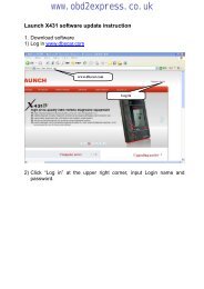
www.obd2express.co.uk6) The selected data will display on the textbox <strong>of</strong> Printer. Byselecting the function keys on the right, you could execute thefollowing operations:Print – Print all data in the textbox to a printer connected toyour computer.Edit – Once clicked, the s<strong>of</strong>tware will automatically open anNOTEPAD window with all recorded data showing on.Copy – Copy all data in the textbox to the clipboard.Clear – Delete all data in the textbox.Exit – Quit the operation.7) You are also allowed to edit, copy, and delete the data in thePrinter window.NOTE: The scan <strong>tool</strong> can only print text data even though thedata is saved in graphic mode.7.2. S<strong>of</strong>tware updateThis function allows you to update the scan <strong>tool</strong> s<strong>of</strong>twarethrough a computer. Register the ToolUser would update the scan <strong>tool</strong> ONLY after you had registered the<strong>tool</strong> on our website: www.auteltech.com. Then you could downloads<strong>of</strong>tware, update online, retrieve information and get warrantyservice.NOTE: Prior to registration, please confirm your network isworking properly.1. Log on the website www.auteltech.com.2. Click on the Update <strong>tool</strong> bar at the top <strong>of</strong> the screen, and then59
www.obd2express.co.ukselect User Register. Or,Click on the Updates column in the lower right corner <strong>of</strong> thescreen, and select Register.3. The screen <strong>of</strong> Register Information appears. Please read throughthe instructions, and click on Agree to continue.4. Put in the Product Serial No. and Register Password, and clickon Next. (Figure 7.2)5. Follow the instructions on screen to finish the registration.NOTE: Please use the Abut function to find out the ProductSerial No. and Register Password. For details, please refer tothe Section 3.6 System Setup. Update ProcedureFigure 7.2Autel frequently releases s<strong>of</strong>tware updates that you can download.The Update feature makes it very easy to determine and get exactlywhat you need.1. Install PC Suit through the included CD, or download theapplications in our website: www.auteltech.com or ourdistributors’ site.2. Make sure that your computer is connected to the Internet.60
www.obd2express.co.uk3. Remove the TF card from the scan <strong>tool</strong>.4. Connect the TF card to computer with a card reader5. Run the update option in PC Suit s<strong>of</strong>tware. Wait for the Log Inwindow to pop up. (Figure 7.3)Figure 7.36. Put in the user name and password and wait for the Updatewindow to display. If you forget your password unintentionally,you may always click the [Forget your password?] to link toour website and find your password back.7. In the Update window, select the items you want to install.Usually, you should install all available updates.Figure 7.461
www.obd2express.co.ukGenerally, there are two ways to update programs:Batch updatingSelect the programs that you would update by clicking on thecheck boxes next to those items. Then click the UpdateSelected Items button on the right side <strong>of</strong> screen.Or, click on the SELECT ALL checkbox on the right side <strong>of</strong>screen and all updatable items will be selected automatically.Then click the Update Selected Items button on the right side<strong>of</strong> screen.Check the updating process by observing the upper left progressbar [downloading] and upper right progress bar [installing]. Youmay also find progress information in the Status column <strong>of</strong>updated items.Anytime you could click the Pause button on the right side <strong>of</strong>screen to suspend all progresses, and the state <strong>of</strong> thosesuspended items would change to STOPPED.To resume updating process, you may need to select thosesuspended items again, then click the Update Selected Itemsbutton. The progress will resume from the break point.When the downloading is completed, the downloaded programswill be installed automatically. The new version will replace theold version.Single updatingFind the desired updating item and click the INSTALL buttonin the same line. With updating in progress, the INSTALLbutton changes to STOP.Check the updating process by observing the upper left progressbar [downloading] and upper right progress bar [installing]. Youmay also find progress information in the Status column <strong>of</strong>updated items.Anytime you could click the Pause button in the line to suspendthis progress, and the state <strong>of</strong> this item would change toSTOPPED.62
www.obd2express.co.ukTo resume updating process, click the INSTALL button in theline again. The progress will resume from the break point.When the downloading is completed, the downloaded programwill be installed automatically. The new version will replace theold version.8. Insert the TF card into the scan <strong>tool</strong>, and restart the scan <strong>tool</strong> t<strong>of</strong>inish the whole update. View or Delete ProgramsTo view the list <strong>of</strong> installed programs or to delete an installedprogram, please follow these steps:Click on the Installed Programs tag entry and the page willshow the list <strong>of</strong> programs installed.Select the program(s) that you would delete. Batch delete: Select the programs that you would delete byclicking on the check boxes to the left <strong>of</strong> those items. Thenclick the DELETE button on the right side <strong>of</strong> screen. Single delete: Click the UNINSTALL button in the line <strong>of</strong>your would-be-deleted program.A window asking “Are you sure to delete the s<strong>of</strong>tware?” willpop up for your confirmation.Figure 7.5Click on Yes to delete the program(s) selected, or on No to63
www.obd2express.co.ukcancel the action.The deleted program will automatically add to the end <strong>of</strong>program list in the UPDATE page in case you would like toinstall again.Theoretically, all programs in latest versions will be automaticallycompatible with the older versions, but if your scan <strong>tool</strong> do have acompatible problem and want to retrieve the older version for someprograms, you may need to delete them first then install the olderversion again. Choose older version from the pull-down menu <strong>of</strong>program version.Figure 7.664
www.obd2express.co.uk8. Warranty and Service8.1. Limited One Year WarrantyAutel warrants to its customers that this product will be free from alldefects in materials and workmanship for a period <strong>of</strong> one (1) year fromthe date <strong>of</strong> the original purchase, subject to the following terms andconditions:1) The sole responsibility <strong>of</strong> Autel under the Warranty is limited toeither the repair or, at the option <strong>of</strong> Autel, replacement <strong>of</strong> the scan<strong>tool</strong> at no charge with Pro<strong>of</strong> <strong>of</strong> Purchase. The sales receipt may beused for this purpose.2) This warranty does not apply to damages caused by improper use,accident, flood, lightning, or if the product was altered or repairedby anyone other than the Manufacturer’s Service Center.3) Autel shall not be liable for any incidental or consequentialdamages arising from the use, misuse, or mounting <strong>of</strong> the scan <strong>tool</strong>.Some states do not allow limitations on how long an impliedwarranty lasts, so the above limitations may not apply to you.4) All information in this manual is based on the latest informationavailable at the time <strong>of</strong> publication and no warranty can be madefor its accuracy or completeness. Autel reserves the right to makechanges at any time without notice.8.2. Service ProceduresIf you have any questions, please contact your local store, distributoror visit our website at www.auteltech.com.If it becomes necessary to return the scan <strong>tool</strong> for repair, contact yourlocal distributor for more information.65