TDR-Manual 2009 - Henseleit Helicopters
TDR-Manual 2009 - Henseleit Helicopters
TDR-Manual 2009 - Henseleit Helicopters

You also want an ePaper? Increase the reach of your titles
YUMPU automatically turns print PDFs into web optimized ePapers that Google loves.
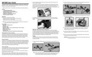
Chapter – I M a i n r o t o r ( Assembly Group 1 )The kit contains 2 red (soft) and 4 black (hard) O-rings which allow for theadjustment of 3 different degrees of damping hardness of the feathering spindle.The degree of hardness depends on which assembly sequence you have chosen.Image 1 shows the softest damping degree that can be changed to achieve thehardest damping degree indicated in image 3. In general, a helicopter having asofter damping degree hovers more calmly und does not tend to shake duringcertain revolutions, if the blade track is not correct.The helicopter´s agility increases slightly with a growing hardness.At the beginning I recommend to follow the assembly according to image 2, as thishardness is a reasonable compromise for a new helicopter where all mechanismsstill have to adapt to each other and to be set up.If the damping degree appears to be too soft after some flights, since the O-ringshave been set, you can choose a harder set-up. The O-rings are covered with asmall amount of ball bearing grease. If you use too much grease, the rings might bepressed out during extreme manoeuvres. Please keep the remaining O-rings for useas spare parts.Align the feathering spindle 0110 such that it is positioned in the centre of the centre hub and push the bearings on bothsides onto the shaft according to the sequence indicated in the image. Do not use excessive forces when pushing thebearings onto the shaft. It is recommended to clamp the shaft into a drilling machine and to treat it carefully with a strip ofsandpaper, if the bearings jam.Do not mix up the different spacer washers 0107 (0.2 mm thick) and 0111 (0.5 mm thick) and please note that the singleparts of the thrust bearings (please grease them before assembly) must be installed in the right way. The ring with the largerinner diameter (8.2 mm) is mounted at first. If you do not follow the instructions correctly the blade holder may wedge. Pleasefill the hollow side of the ball cage with grease and install it pointing to the centre hub.The blade holder support 0112 has a countersink on one side which has to point to the centre hub.10