TDR-Manual 2009 - Henseleit Helicopters
TDR-Manual 2009 - Henseleit Helicopters
TDR-Manual 2009 - Henseleit Helicopters

You also want an ePaper? Increase the reach of your titles
YUMPU automatically turns print PDFs into web optimized ePapers that Google loves.
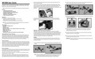
(Bag 9-V)This image shows the assembly of the tail rotor of the right-hand rotation system. When chosing a left-hand rotation systemthe entire gear box is assembled in a mirror-inverted way and turned by 180°, so that the tail rotor points to the left (accordingto the flight direction).Attention ! In both cases the blade holders have to be turned such that the front edge of the blade pointing to the top pointsinto the flight direction. If you look at the tail rotor of a right-hand rotation system from the right side, it rotates clockwisely andif you look at the tail rotor of a left-hand rotation system from the left side, it rotates anti-clockwisely. In any case the bladeholder is controlled from the front (according to the rotation direction).Pull the drive shaft 0810 slightly out of the boom and cover the end with a small amount of Loctite. Slide the adjusting ring0801 on the end of the shaft so that the M4 threaded hole is aligned to the hole of the drive shaft. Provisorily screw anoptional M4 screw into the hole to check if the holes are aligned before the Loctite hardens. The screw should be screwed inup to the half of the drive shaft. Pull the adjustment ring to the back until the screw reaches the edge of the tube hole and letthe Loctite become dry.Then the adjustment ring protrudes from the the drive shaft to the back by some tenth millimetres. This makes sure that theadjustment ring hits as a stop against the inner ring of the ball bearing in the gear box.Remove the excessive Loctite in front of the adjustment ring and in the drive tube so that it does not stick to the tail inputshaft 0904 later.Slightly cover the grub screw 0801a with Loctite. Mind that Loctite does not get between the adjusting ring and the drive shaft(otherwise they cannot be separated any more).Then the drive shaft is put onto the stop of the input shaft 0904.Please make sure that you press the adjusting ring completely against the inner ring of the bearing and that at the same timeyou press the input shaft 0904 with a gear wheel from the back into the drive housing until it reaches the stop, so that theaxial play is removed.The adjusting ring 0901 does not only make a connection but also secures the input shaft from being axially displaced.Use a high-quality 90° offset Allen wrench to tighten the grub screw M4x4 well.The grub screw has to be pressed through the hole on the side of the drive shaft and then onto the flat area of the tail inputshaft.Now you can press the gear into the boom and tighten it.At first the box can only be pushed in until the front side of the drive shaft reaches the clutch 0231. At this moment slightlyturn the conic pinion 0824 of the tail drive at the front until the shaft slips into the hole. After additional 3mm the gear cannotbe pressed further because the front driving cross-pin of the shaft reaches the front side of the clutch. Turn the conic pinionwhile simultaneously pushing the tail rotor housing until the cross-pin engages in the slot. Now you have to make some effortto push the gear into the tail boom until it reaches the stop. Then it has to be screwed to the two parts 0937 and 0938 as wellas to the vertical tail (secure all screws with Loctite).28