TDR-Manual 2009 - Henseleit Helicopters
TDR-Manual 2009 - Henseleit Helicopters
TDR-Manual 2009 - Henseleit Helicopters

Create successful ePaper yourself
Turn your PDF publications into a flip-book with our unique Google optimized e-Paper software.
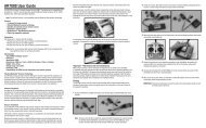
Warning:The connector of the gyro sensor must only beconnected to the provided 3-pin socket (sensor 1).Connecting it to the 4-pin socket above for the controlelement or the servo inputs leads to its immediatedestruction.Connection planV-StabiTail ServoChannel 4Channel 3Channel 2Channel 1V-StabiRudderCollectiveAileronElevatorAuxServos– Tail servo– remains free or is used for the second voltage supply (slave connector from the Jive controller)– CYCLIC servo right– CYCLIC servo left– FORE & AFT CYCLIC servoReceiver outputs– Tail– Pitch– Cyclic roll– Fore & aft cyclic– Sensitivity of tail (here you can provide a connection to a free receiver channel allowing to adjust differenttail gyro sensitivities depending on the flight condition (generally dependent on the rotor speed) using thetransmitter.Installation of the softwareInsert the Installation CD in your CD/DVD drive of your PC and follow the setup instructions. After the setup has beencompleted you have to install the USB driver for the central unit, in order to communicate with the system. In normal case thisshould be carried out automatically as soon as you connect the system for the first time (not yet any current at the system).This is not necessary, if you already have installed a previous version of the V-Stabi on this PC.38