TDR-Manual 2009 - Henseleit Helicopters
TDR-Manual 2009 - Henseleit Helicopters
TDR-Manual 2009 - Henseleit Helicopters

Create successful ePaper yourself
Turn your PDF publications into a flip-book with our unique Google optimized e-Paper software.
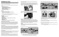
Chapter – X Assembly and struts of the tail boom ( Assembly Group 8 )At first push the tail boom into the clamping flanges of the mechanics as already described on page 16 and adjust the correctposition of the pinion to the crown gear. This is easy, if you have wrapped, as recommended, an adhesive tape around theboom at the corresponding place. Tighten the nuts of the two lower threaded rods to locate the tail boom in position.Attention! Don´t tighten the nut of the bottom thread rod 0237a from the front boom support 0232 to hard because this candamage the bearing 0828b of the bearing flange 0828a because of to much pressure onto the flange.The strut clamp 0809 with the push rod guide from the tail boom assembly group can be put onto the tail boom before orsubsequently. It can be widened far enough without breaking.Mount the boom support ends on both sides of the tail struts (see image above). At first, attach the M3.5 threaded rod 0807aon one side using superglue, so that it still protrudes by 12mm (upper drawing). Put the threaded side into the carbon boomwhich has been sawed off and de-burred only roughly because in this area the thread is mostly damaged.On the opposite side the boom support end 0805 is glued with superglue (lower drawing). Roughen the first 10mm of thecarbon strut using some sandpaper and push the boom support end until it reaches the stop. Only cover the carbon strutthinly and use a larger amount of glue for the hole of the support end. Immediately wipe off leaking superglue.After the glue has dried the two ball links 0807 are attached up to approx. 1mm before the carbon boom and aligned suchthat the eye is parallel to the hole of the boom support end 0805.Attention ! When assembling the attaching balls 0804 you have the possibility to mount them from outside or insidedepending on if you wish to remove the battery later from behind or not. It is recommended to mount the balls from inside(unlikely as shown in the drawing), because it is not reasonable to pull the battery out to the back. It is logical that theconnecting plugs are located at the front and the canopy can be removed easily to pull out the battery comfortably to thefront. If the balls are located inside, the boom support ends look even more elegantly and aerodynamically. In addition, thelens head screw 0804a can be tightened more easily from outside (secure with Loctite). Before tightening the struts loosely atthe front of the balls, they should be tightened loosely at the back to the plastic clamp 0809 using the M3x25 screw 0805aand the nut 0805b. At first press only one strut front side on the ball and then hold the second side loosely on the other ball tosee if both struts have the same length. Correct the length of the second strut by turning in and out the ball link 0807 until it issuitable and then also press it onto the ball. Look at the helicopter from behind to align the clamp 0809 vertically and tightenthe caphead screw until the gap has disappeared.30