GS1 EPC Tag Data Standard 1.6 - Indicod-Ecr
GS1 EPC Tag Data Standard 1.6 - Indicod-Ecr
GS1 EPC Tag Data Standard 1.6 - Indicod-Ecr
- No tags were found...

You also want an ePaper? Increase the reach of your titles
YUMPU automatically turns print PDFs into web optimized ePapers that Google loves.
12345678910111213141516171819202122<strong>GS1</strong> <strong>EPC</strong> <strong>Tag</strong> <strong>Data</strong> <strong>Standard</strong> <strong>1.6</strong>Ratified <strong>Standard</strong>9 September, 2011Disclaimer<strong>GS1</strong> AISBL (<strong>GS1</strong>) is providing this document as a free service to interested industries.This document was developed through a consensus process of interested parties indeveloping the <strong>Standard</strong>. Although efforts have been made to assure that the documentis correct, reliable, and technically accurate, <strong>GS1</strong> makes NO WARRANTY, EXPRESSOR IMPLIED, THAT THIS DOCUMENT IS CORRECT, WILL NOT REQUIREMODIFICATION AS EXPERIENCE AND TECHNOLOGY DICTATE, OR WILL BESUITABLE FOR ANY PURPOSE OR WORKABLE IN ANY APPLICATION, OROTHERWISE. Use of this document is with the understanding that <strong>GS1</strong> DISCLAIMSALL WARRANTIES, EXPRESS OR IMPLIED, INCLUDING BUT NOT LIMITED TO ANYIMPLIED WARRANTY OF NON-INFRINGEMENT OF PATENTS OR COPYRIGHTS,MERCHANTABILITY AND/OR FITNESS FOR A PARTICULAR PURPOSE, THAT THEINFORMATION IS ERROR FREE, NOR SHALL <strong>GS1</strong> BE LIABLE FOR DAMAGES OFANY KIND, INCLUDING DIRECT, INDIRECT, INCIDENTAL, SPECIAL,CONSEQUENTIAL OR EXEMPLARY DAMAGES, ARISING OUT OF USE OR THEINABILITY TO USE INFORMATION CONTAINED HEREIN OR FROM ERRORSCONTAINED HEREIN.2324© 2011 <strong>GS1</strong> AISBLCopyright Notice25262728All rights reserved. Unauthorized reproduction, modification, and/or use of this document arenot permitted. Requests for permission to reproduce and/or use this document should beaddressed to <strong>GS1</strong> Global Office, Attention Legal Department, Avenue Louise 326, bte 10, B-1050 Brussels, Belgium.29Copyright ©2005- 2011 <strong>GS1</strong> AISBL, All Rights Reserved. Page 1 of 218
303132333435363738394041424344454647484950515253545556575859606162AbstractThe <strong>EPC</strong> <strong>Tag</strong> <strong>Data</strong> <strong>Standard</strong> defines the Electronic Product Code, and also specifiesthe memory contents of Gen 2 RFID <strong>Tag</strong>s. In more detail, the <strong>Tag</strong> <strong>Data</strong> <strong>Standard</strong> coverstwo broad areas: The specification of the Electronic Product Code, including its representation atvarious levels of the <strong>EPC</strong>global Architecture and its correspondence to <strong>GS1</strong> keys andother existing codes. The specification of data that is carried on Gen 2 RFID tags, including the <strong>EPC</strong>, “usermemory” data, control information, and tag manufacture information.Audience for this documentThe target audience for this specification includes: <strong>EPC</strong> Middleware vendors RFID <strong>Tag</strong> users and encoders Reader vendors Application developers System integratorsDifferences From <strong>EPC</strong> <strong>Tag</strong> <strong>Data</strong> <strong>Standard</strong> Version 1.5The <strong>EPC</strong> <strong>Tag</strong> <strong>Data</strong> <strong>Standard</strong> Version <strong>1.6</strong> is fully backward-compatible with <strong>EPC</strong> <strong>Tag</strong><strong>Data</strong> <strong>Standard</strong> Version 1.5.The <strong>EPC</strong> <strong>Tag</strong> <strong>Data</strong> <strong>Standard</strong> Version <strong>1.6</strong> includes these new or enhanced features:A new <strong>EPC</strong> Scheme, the Aerospace and Defense Identifier (ADI) scheme, has beenadded (Sections 6.3.10, 10.11, and 14.5.10).The correspondence between ISBN, ISMN, and ISSN (<strong>GS1</strong> Prefixes 977, 978, or979) and the SGTIN <strong>EPC</strong> has been revised to reflect the latest ISBN and ISMNstandards (Section 7.1.7)The meaning of the term “SGLN” has been clarified (Section 6.3.3). The letter “S”no longer stands for the word “serialized,” but merely indicates that the SGLN maycorrespond to either a GLN without extension or a GLN with an extension.The grammar for the <strong>EPC</strong> Raw URI (Section 12.4) has been corrected to allow for thecase of a Gen2 RFID <strong>Tag</strong> whose <strong>EPC</strong> bank length bits are set to zero.A new section has been added (Section 18) which defines what it means to conformto the <strong>EPC</strong> <strong>Tag</strong> <strong>Data</strong> <strong>Standard</strong>. Additional examples have been added to Appendix E.Copyright ©2005- 2011 <strong>GS1</strong> AISBL, All Rights Reserved. Page 2 of 218
63646566In Appendix F, the Packed Objects ID Table for <strong>Data</strong> Format 9 has been updated toaccount for recent <strong>GS1</strong> General Specifications changes to the definitions of AI 253and AI 8110.Various typographical errors have been corrected.6768697071727374Status of this documentThis section describes the status of this document at the time of its publication. Otherdocuments may supersede this document. The latest status of this document series ismaintained at <strong>EPC</strong>global. See http://www.epcglobalinc.org/standards/for more information.This version of the <strong>EPC</strong> <strong>Tag</strong> <strong>Data</strong> <strong>Standard</strong> is the Ratified version of the standard and hascompleted all GSMP steps.Comments on this document should be sent to the GSMP@gs1.org .75Copyright ©2005- 2011 <strong>GS1</strong> AISBL, All Rights Reserved. Page 3 of 218
21121221321421521621721821922022122222322422522622722822923023123223323423523623723823924024124224324424516.2.4 BlockWrite and BlockErase Segment....................................................12116.2.5 User Memory and BlockPermaLock Segment.......................................12416.3 Serialized <strong>Tag</strong> Identification (STID)............................................................12516.3.1 STID URI Grammar .............................................................................12516.3.2 Decoding Procedure: TID Bank Contents to STID URI.........................12617 User Memory Bank Contents.............................................................................12618 Conformance .....................................................................................................12818.1 Conformance of RFID <strong>Tag</strong> <strong>Data</strong>..................................................................12818.1.1 Conformance of Reserved Memory Bank (Bank 00) .............................12818.1.2 Conformance of <strong>EPC</strong> Memory Bank (Bank 01) ....................................12818.1.3 Conformance of TID Memory Bank (Bank 10) .....................................12918.1.4 Conformance of User Memory Bank (Bank 11) ....................................12918.2 Conformance of Hardware and Software Components.................................12918.2.1 Conformance of Hardware and Software Components That Produce orConsume Gen 2 Memory Bank Contents...............................................................13018.2.2 Conformance of Hardware and Software Components that Produce orConsume URI Forms of the <strong>EPC</strong>...........................................................................13118.2.3 Conformance of Hardware and Software Components that TranslateBetween <strong>EPC</strong> Forms .............................................................................................13318.3 Conformance of Human Readable Forms of the <strong>EPC</strong> and of <strong>EPC</strong> MemoryBank Contents..........................................................................................................133Appendix A Character Set for Alphanumeric Serial Numbers................................134Appendix B Glossary (non-normative) ..................................................................136Appendix C References .........................................................................................141Appendix D Extensible Bit Vectors .......................................................................141Appendix E (non-normative) Examples: <strong>EPC</strong> Encoding and Decoding...................142E.1 Encoding a Serialized Global Trade Item Number (SGTIN) to SGTIN-96......143E.2 Decoding an SGTIN-96 to a Serialized Global Trade Item Number (SGTIN) 145E.3 Summary Examples of All <strong>EPC</strong> Schemes .......................................................147Appendix F Packed Objects ID Table for <strong>Data</strong> Format 9..........................................149F.1 Tabular Format (non-normative).....................................................................150F.2 Comma-Separated-Value (CSV) Format.........................................................159Appendix G 6-Bit Alphanumeric Character Set .....................................................162Appendix H (Intentionally Omitted) ......................................................................163Appendix I Packed Objects Structure ......................................................................163Copyright ©2005- 2011 <strong>GS1</strong> AISBL, All Rights Reserved. Page 8 of 218
246247248249250251252253254255256257258259260261262263264265266267268269270271272273274275276277278279I.1 Overview........................................................................................................163I.2 Overview of Packed Objects Documentation ..................................................163I.3 High-Level Packed Objects Format Design ....................................................164I.3.1 Overview .................................................................................................164I.3.2 Descriptions of each section of a Packed Object’s structure......................165I.4 Format Flags section.......................................................................................167I.4.1 <strong>Data</strong> Terminating Flag Pattern..................................................................168I.4.2 Format Flag section starting bit patterns ...................................................168I.4.3 IDLPO Format Flags................................................................................168I.4.4 Patterns for use between Packed Objects..................................................169I.5 Object Info section ........................................................................................169I.5.1 Object Info formats ..................................................................................170I.5.1.1 IDLPO default Object Info format .....................................................170I.5.1.2 IDLPO non-default Object Info format ..............................................171I.5.1.3 IDMPO Object Info format................................................................172I.5.2 Length Information ..................................................................................172I.5.3 General description of ID values ..............................................................173I.5.3.1 Application Indicator subsection........................................................174I.5.3.2 Full/Restricted Use bits......................................................................175I.5.4 ID Values representation in an ID Value-list Packed Object .....................175I.5.5 ID Values representation in an ID Map Packed Object .............................176I.5.6 Optional Addendum subsection of the Object Info section .......................176I.5.6.1 Addendum “EditingOP” list (only in ID List Packed Objects)............177I.5.6.2 Packed Objects containing an Addendum subsection .........................177I.6 Secondary ID Bits section...............................................................................178I.7 Aux Format section ........................................................................................178I.7.1 Support for No-Directory compaction methods ........................................179I.7.2 Support for the Packed-Object compaction method ..................................179I.8 <strong>Data</strong> section....................................................................................................180I.8.1 Known-length-Numerics subsection of the <strong>Data</strong> Section ..........................181I.8.2 Alphanumeric subsection of the <strong>Data</strong> section ...........................................181I.8.2.1 A/N Header Bits ................................................................................182I.8.2.2 Dual-base Character-map encoding....................................................182I.8.2.3 Prefix and Suffix Run-Length encoding .............................................183Copyright ©2005- 2011 <strong>GS1</strong> AISBL, All Rights Reserved. Page 9 of 218
280281282283284285286287288289290291292293294295296297298299300301302303304305306307308309310311312313I.8.2.4 Encoding into Binary Segments .........................................................183I.8.2.5 Padding the last Byte .........................................................................184I.9 ID Map and Directory encoding options .........................................................184I.9.1 ID Map Section structure .........................................................................185I.9.1.1 ID Map and ID Map bit field .............................................................186I.9.1.2 <strong>Data</strong>/Directory and AuxMap indicator bits.........................................187I.9.1.3 Closing Flags bit(s)............................................................................187I.9.2 Directory Packed Objects.........................................................................187I.9.2.1 ID Maps in a Directory IDMPO.........................................................187I.9.2.2 Optional AuxMap Section (Directory IDMPOs only).........................187I.9.2.3 Usage as a Presence/Absence Directory.............................................190I.9.2.4 Usage as an Indexed Directory...........................................................190Appendix J Packed Objects ID Tables .....................................................................191J.1 Packed Objects <strong>Data</strong> Format registration file structure....................................191J.1.1 File Header section...................................................................................192J.1.2 Table Header section................................................................................193J.1.3 ID Table section.......................................................................................194J.2 Mandatory and Optional ID Table columns ....................................................194J.2.1 IDvalue column (Mandatory) ...................................................................194J.2.2 OIDs and IDstring columns (Optional).....................................................194J.2.3 FormatString column (Optional) ..............................................................196J.2.4 Interp column (Optional)..........................................................................196J.3 Syntax of OIDs, IDstring, and FormatString Columns ....................................197J.3.1 Semantics for OIDs, IDString, and FormatString Columns.......................197J.3.2 Formal Grammar for OIDs, IDString, and FormatString Columns............198J.4 OID input/output representation......................................................................200J.4.1 “ID Value OID” output representation......................................................200Appendix K Packed Objects Encoding tables.........................................................201Appendix L Encoding Packed Objects (non-normative)............................................207Appendix M Decoding Packed Objects (non-normative) ........................................211M.1 Overview.....................................................................................................211M.2 Decoding Alphanumeric data ......................................................................213Appendix N Acknowledgement of Contributors and Companies Opted-in during theCreation of this <strong>Standard</strong> (Informative) .......................................................................215Copyright ©2005- 2011 <strong>GS1</strong> AISBL, All Rights Reserved. Page 10 of 218
314315316317318319320321322323324325326327328329330331332333334335336337338339340341342343344345346List of FiguresFigure 1. Organization of the <strong>EPC</strong> <strong>Tag</strong> <strong>Data</strong> <strong>Standard</strong>...............................................17Figure 2. Example Visibility <strong>Data</strong> Stream .................................................................20Figure 3. Illustration of GRAI Identifier Namespace .................................................21Figure 4. Illustration of <strong>EPC</strong> Identifier Namespace ...................................................22Figure 5. Illustration of Relationship of <strong>GS1</strong> Key and <strong>EPC</strong> Identifier Namespaces....23Figure 6. <strong>EPC</strong>global Architecture Framework and <strong>EPC</strong> Structures Used at Each Level26Figure 7. Correspondence between SGTIN <strong>EPC</strong> URI and <strong>GS1</strong> Element String .........39Figure 8. Correspondence between SSCC <strong>EPC</strong> URI and <strong>GS1</strong> Element String ...........43Figure 9. Correspondence between SGLN <strong>EPC</strong> URI without extension and <strong>GS1</strong>Element String...............................................................................................................44Figure 10. Correspondence between SGLN <strong>EPC</strong> URI with extension and <strong>GS1</strong>Element String...............................................................................................................45Figure 11. Correspondence between GRAI <strong>EPC</strong> URI and <strong>GS1</strong> Element String ........46Figure 12. Correspondence between GIAI <strong>EPC</strong> URI and <strong>GS1</strong> Element String .........48Figure 13. Correspondence between GSRN <strong>EPC</strong> URI and <strong>GS1</strong> Element String .......49Figure 14. Correspondence between GDTI <strong>EPC</strong> URI and <strong>GS1</strong> Element String ........50Figure 15. Gen 2 <strong>Tag</strong> Memory Map.........................................................................56Figure 16. Gen 2 Protocol Control (PC) Bits Memory Map......................................59Figure 17. Illustration of <strong>EPC</strong> <strong>Tag</strong> URI and <strong>EPC</strong> Raw URI......................................67Figure 18. Illustration of Filter Value Within <strong>EPC</strong> <strong>Tag</strong> URI.....................................68List of TablesTable 1. <strong>EPC</strong> Schemes and Corresponding <strong>GS1</strong> Keys..............................................24Table 2. <strong>EPC</strong> Schemes and Where the Pure Identity Form is Defined ......................30Table 3. Kinds of <strong>Data</strong> on a Gen 2 RFID <strong>Tag</strong> ..........................................................55Table 4. Gen 2 Memory Map...................................................................................58Table 5. Gen 2 Protocol Control (PC) Bits Memory Map.........................................60Table 6. SGTIN Filter Values ..................................................................................61Table 7. SSCC Filter Values ....................................................................................62Table 8. SGLN Filter Values ...................................................................................62Table 9. GRAI Filter Values ....................................................................................62Copyright ©2005- 2011 <strong>GS1</strong> AISBL, All Rights Reserved. Page 11 of 218
381382383384385386387388389presence of a segment, and address location of a segment depends on the XTID Header.119Table 43. The XTID header .....................................................................................120Table 44. Optional Command Support XTID Word.................................................121Table 45. XTID Block Write and Block Erase Information......................................124Table 46. XTID Block PermaLock and User Memory Information ..........................125Table 47. Characters Permitted in Alphanumeric Serial Numbers ............................136Table 48. Characters Permitted in 6-bit Alphanumeric Fields...................................163390Copyright ©2005- 2011 <strong>GS1</strong> AISBL, All Rights Reserved. Page 13 of 218
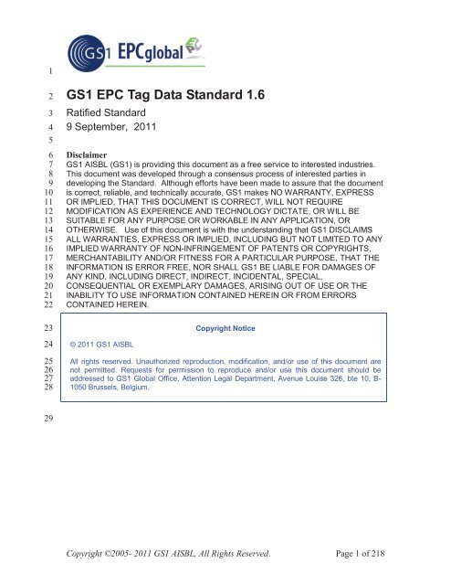
473474475476477478479480481482483readable <strong>EPC</strong> URIs, and <strong>EPC</strong> identifiers derived from bar code data following theprocedures in this standard).The term “Electronic Product Code” (or “<strong>EPC</strong>”) is used when referring to the <strong>EPC</strong>regardless of the concrete form used to represent it. The term “Pure Identity <strong>EPC</strong> URI” isused to refer specifically to the text form the <strong>EPC</strong> takes within computer systems,including electronic documents, databases, and electronic messages. The term “<strong>EPC</strong>Binary Encoding” is used specifically to refer to the form the <strong>EPC</strong> takes within thememory of RFID tags.The following diagram illustrates the parts of the <strong>Tag</strong> <strong>Data</strong> <strong>Standard</strong> and how they fittogether. (The colors in the diagram refer to the types of data that may be stored onRFID tags, explained further in Section 9.1.)Copyright ©2005- 2011 <strong>GS1</strong> AISBL, All Rights Reserved. Page 16 of 218
<strong>EPC</strong> “pure identity”URI (Section 6)Correspondencespecified inSection 6.3.10<strong>GS1</strong> keys(specified in[<strong>GS1</strong><strong>GS1</strong>0.0])<strong>GS1</strong> AIs(specified in[<strong>GS1</strong><strong>GS1</strong>0.0])Independent of RFID+ Other <strong>Data</strong>RFID-SpecificAttribute Bits(Section 11)Filter Values(Section 10)Key= Business <strong>Data</strong><strong>EPC</strong> “tag URI”(Section 12)= Control Info= Biz <strong>Data</strong> + Control= <strong>Tag</strong> Manufacture Info<strong>EPC</strong> binary encoding(Section 14)Reserved Bankcontents(specified in[UHFC1G2])<strong>EPC</strong> Bankcontents(Section 14.5.10)TID Bankcontents(Section 16)User MemoryBank contents(Section 17)484485486487488489490491492493Gen 2 RFID <strong>Tag</strong> (specified in [UHFC1G2])Figure 1. Organization of the <strong>EPC</strong> <strong>Tag</strong> <strong>Data</strong> <strong>Standard</strong>The first few sections define those aspects of the Electronic Product Code that areindependent from RFID.Section 4 provides an overview of the Electronic Product Code (<strong>EPC</strong>) and how it relatesto other <strong>EPC</strong>global standards and the <strong>GS1</strong> General Specifications.Section 6 specifies the Pure Identity <strong>EPC</strong> URI form of the <strong>EPC</strong>. This is a textual form ofthe <strong>EPC</strong>, and is recommended for use in business applications and business documents asa universal identifier for any physical object for which visibility information is kept. Inparticular, this form is what is used as the “what” dimension of visibility data in the <strong>EPC</strong>Copyright ©2005- 2011 <strong>GS1</strong> AISBL, All Rights Reserved. Page 17 of 218
494495496497498499500501502503504505506507508509510511512513514515516517518519520521522523524525526527528529530531532533534535536537Information Services (<strong>EPC</strong>IS) specification, and is also available as an output from theApplication Level Events (ALE) interface.Section 7 specifies the correspondence between Pure Identity <strong>EPC</strong> URIs as defined inSection 6 and bar code element strings as defined in the <strong>GS1</strong> General Specifications.Section 8 specifies the Pure Identity Pattern URI, which is a syntax for representing setsof related <strong>EPC</strong>s, such as all <strong>EPC</strong>s for a given trade item regardless of serial number.The remaining sections address topics that are specific to RFID, including RFID-specificforms of the <strong>EPC</strong> as well as other data apart from the <strong>EPC</strong> that may be stored on Gen 2RFID tags.Section 9 provides general information about the memory structure of Gen 2 RFID <strong>Tag</strong>s.Sections 10 and 11 specify “control” information that is stored in the <strong>EPC</strong> memory bankof Gen 2 tags along with a binary-encoded form of the <strong>EPC</strong> (<strong>EPC</strong> Binary Encoding).Control information is used by RFID data capture applications to guide the data captureprocess by providing hints about what kind of object the tag is affixed to. Controlinformation is not part of the <strong>EPC</strong>, and does comprise any part of the unique identity of atagged object. There are two kinds of control information specified: the “filter value”(Section 10) that makes it easier to read desired tags in an environment where there maybe other tags present, such as reading a pallet tag in the presence of a large number ofitem-level tags, and “attribute bits” (Section 11) that provide additional special attributeinformation such as alerting to the presence of hazardous material. The same “attributebits” are available regardless of what kind of <strong>EPC</strong> is used, whereas the available “filtervalues” are different depending on the type of <strong>EPC</strong> (and with certain types of <strong>EPC</strong>s, nofilter value is available at all).Section 12 specifies the “tag” Uniform Resource Identifiers, which is a compact stringrepresentation for the entire data content of the <strong>EPC</strong> memory bank of Gen 2 RFID <strong>Tag</strong>s.This data content includes the <strong>EPC</strong> together with “control” information as defined inSections 10 and 11. In the “tag” URI, the <strong>EPC</strong> content of the <strong>EPC</strong> memory bank isrepresented in a form similar to the Pure Identity <strong>EPC</strong> URI. Unlike the Pure Identity<strong>EPC</strong> URI, however, the “tag” URI also includes the control information content of the<strong>EPC</strong> memory bank. The “tag” URI form is recommended for use in capture applicationsthat need to read control information in order to capture data correctly, or that need towrite the full contents of the <strong>EPC</strong> memory bank. “<strong>Tag</strong>” URIs are used in the ApplicationLevel Events (ALE) interface, both as an input (when writing tags) and as an output(when reading tags).Section 13 specifies the <strong>EPC</strong> <strong>Tag</strong> Pattern URI, which is a syntax for representing sets ofrelated RFID tags based on their <strong>EPC</strong> content, such as all tags containing <strong>EPC</strong>s for agiven range of serial numbers for a given trade item.Sections 14 and 14.5.10 specify the contents of the <strong>EPC</strong> memory bank of a Gen 2 RFIDtag at the bit level. Section 14 specifies how to translate between the the “tag” URI andthe <strong>EPC</strong> Binary Encoding. The binary encoding is a bit-level representation of what isactually stored on the tag, and is also what is carried via the Low Level Reader Protocol(LLRP) interface. Section 14.5.10 specifies how this binary encoding is combined withattribute bits and other control information in the <strong>EPC</strong> memory bank.Section 16 specifies the binary encoding of the TID memory bank of Gen 2 RFID <strong>Tag</strong>s.Copyright ©2005- 2011 <strong>GS1</strong> AISBL, All Rights Reserved. Page 18 of 218
538539540541542543544545546547548549550551552553554555556557558559560561562563564565566567568569Section 17 specifies the binary encoding of the User memory bank of Gen 2 RFID <strong>Tag</strong>s.4 The Electronic Product Code: A Universal Identifierfor Physical ObjectsThe Electronic Product Code is designed to facilitiate business processes and applicationsthat need to manipulate visibility data – data about observations of physical objects. The<strong>EPC</strong> is a universal identifier that provides a unique identity for any physical object. The<strong>EPC</strong> is designed to be unique across all physical objects in the world, over all time, andacross all categories of physical objects. It is expressly intended for use by businessapplications that need to track all categories of physical objects, whatever they may be.By contrast, seven <strong>GS1</strong> identification keys defined in the <strong>GS1</strong> General Specifications[<strong>GS1</strong><strong>GS1</strong>0.0] can identify categories of objects (GTIN), unique objects (SSCC, GLN,GIAI, GSRN), or a hybrid (GRAI, GDTI) that may identify either categories or uniqueobjects depending on the absence or presence of a serial number. (Two other keys, GINCand GSIN, identify logical groupings, not physical objects.) The GTIN, as the onlycategory identification key, requires a separate serial number to uniquely identify anobject but that serial number is not considered part of the identification key.There is a well-defined correspondence between <strong>EPC</strong>s and <strong>GS1</strong> keys. This allows anyphysical object that is already identified by a <strong>GS1</strong> key (or <strong>GS1</strong> key + serial numbercombination) to be used in an <strong>EPC</strong> context where any category of physical object may beobserved. Likewise, it allows <strong>EPC</strong> data captured in a broad visibility context to becorrelated with other business data that is specific to the category of object involved andwhich uses <strong>GS1</strong> keys.The remainder of this section elaborates on these points.4.1 The Need for a Universal Identifier: an ExampleThe following example illustrates how visibility data arises, and the role the <strong>EPC</strong> plays asa unique identifier for any physical object. In this example, there is a storage room in ahospital that holds radioactive samples, among other things. The hospital safety officerneeds to track what things have been in the storage room and for how long, in order toensure that exposure is kept within acceptable limits. Each physical object that mightenter the storage room is given a unique Electronic Product Code, which is encoded ontoan RFID <strong>Tag</strong> affixed to the object. An RFID reader positioned at the storage room doorgenerates visibility data as objects enter and exit the room, as illustrated below.Copyright ©2005- 2011 <strong>GS1</strong> AISBL, All Rights Reserved. Page 19 of 218
RFID ReaderHospitalStorage Room570571572573574575576577578579580581582583Time In /OutVisibility <strong>Data</strong> Stream at Storage Room Entrance<strong>EPC</strong>Figure 2. Example Visibility <strong>Data</strong> StreamComment8:23am In urn:epc:id:sgtin:0614141.012345.62852 10cc Syringe#62852 (trade item)8:52am In urn:epc:id:grai:0614141.54321.2528 Pharma Tote #2528(reusable transport)8:59am In urn:epc:id:sgtin:0614141.012345.1542 10cc Syringe #1542(trade item)9:02am Out urn:epc:id:giai:0614141.17320508 Infusion Pump #52(fixed asset)9:32am In urn:epc:id:gsrn:0614141.0000010253 Nurse Jones(service relation)9:42am Out urn:epc:id:gsrn:0614141.0000010253 Nurse Jones(service relation)9:52am In urn:epc:id:gdti:0614141.00001.1618034 Patient Smith’schart (document)As the illustration shows, the data stream of interest to the safety officer is a series ofevents, each identifying a specific physical object and when it entered or exited the room.The unique <strong>EPC</strong> for each object is an identifier that may be used to drive the businessprocess. In this example, the <strong>EPC</strong> (in Pure Identity <strong>EPC</strong> URI form) would be a primarykey of a database that tracks the accumulated exposure for each physical object; eachentry/exit event pair for a given object would be used to update the accumulated exposuredatabase.This example illustrates how the <strong>EPC</strong> is a single, universal identifier for any physicalobject. The items being tracked here include all kinds of things: trade items, reusabletransports, fixed assets, service relations, documents, among others that might occur. Byusing the <strong>EPC</strong>, the application can use a single identifier to refer to any physical object,and it is not necessary to make a special case for each category of thing.Copyright ©2005- 2011 <strong>GS1</strong> AISBL, All Rights Reserved. Page 20 of 218
5845855865875885895905915925935945955965975985994.2 Use of Identifiers in a Business <strong>Data</strong> ContextGenerally speaking, an identifier is a member of set (or “namespace”) of strings (names),such that each identifier is associated with a specific thing or concept in the real world.Identifiers are used within information systems to refer to the real world thing or conceptin question. An identifier may occur in an electronic record or file, in a database, in anelectronic message, or any other data context. In any given context, the producer andconsumer must agree on which namespace of identifiers is to be used; within that context,any identifier belonging to that namespace may be used.The keys defined in the <strong>GS1</strong> General Specifications [<strong>GS1</strong><strong>GS1</strong>0.0] are each a namespaceof identifiers for a particular category of real-world entity. For example, the GlobalReturnable Asset Identifier (GRAI) is a key that is used to identify returnable assets, suchas plastic totes and pallet skids. The set of GRAI codes can be thought of as identifiersfor the members of the set “all returnable assets.” A GRAI code may be used in a contextwhere only returnable assets are expected; e.g., in a rental agreement from a movingservices company that rents returnable plastic crates to customers to pack during a move.This is illustrated below.GRAI = 0614141000234AB23 (100 liter tote #AB23)GRAI = 0614141000234AB24 (100 liter tote #AB24)GRAI = 0614141000517XY67 (500 liter tote #XY67)GRAIs: Allreturnable assetsEstablishes the context as returnable assets600601602603604Therefore, any GRAI could go here(and nothing else)0614141000234AB230614141000517XY67…Figure 3. Illustration of GRAI Identifier NamespaceThe upper part of the figure illustrates the GRAI identifier namespace. The lower part ofthe figure shows how a GRAI might be used in the context of a rental agreement, whereonly a GRAI is expected.Copyright ©2005- 2011 <strong>GS1</strong> AISBL, All Rights Reserved. Page 21 of 218
<strong>EPC</strong> = urn:epc:id:sgtin:0614141.012345.62852(10cc Syringe #62852 – trade item)<strong>EPC</strong> = urn:epc:id:grai:0614141.54321.2528(Pharma Tote #2528 – reusable asset)<strong>EPC</strong>s:All physical objectsEstablishes the context as all physical objectsTherefore, any <strong>EPC</strong> could go here605606607608609610611612613614615616617618619620621622urn:epc:id:sgtin:0614141.012345.62852urn:epc:id:grai:0614141.54321.2528…Figure 4. Illustration of <strong>EPC</strong> Identifier NamespaceIn contrast, the <strong>EPC</strong> namespace is a space of identifiers for any physical object. The setof <strong>EPC</strong>s can be thought of as identifiers for the members of the set “all physical objects.”<strong>EPC</strong>s are used in contexts where any type of physical object may appear, such as in theset of observations arising in the hospital storage room example above. Note that the<strong>EPC</strong> URI as illustrated in Figure 4 includes strings such as sgtin, grai, and so on aspart of the <strong>EPC</strong> URI identifier. This is in contrast to <strong>GS1</strong> Keys, where no such indicationis part of the key itself (instead, this is indicated outside of the key, such as in the XMLelement name in the example in Figure 3, or in the Application Identifier (AI)that accompanies a <strong>GS1</strong> Key in a <strong>GS1</strong> Element String).4.3 Relationship Between <strong>EPC</strong>s and <strong>GS1</strong> KeysThere is a well-defined relationship between <strong>EPC</strong>s and <strong>GS1</strong> keys. For each <strong>GS1</strong> key thatdenotes an individual physical object (as opposed to a class), there is a corresponding<strong>EPC</strong>. This correspondence is formally defined by conversion rules specified in Section 7,which define how to map a <strong>GS1</strong> key to the corresponding <strong>EPC</strong> value and vice versa. Thewell-defined correspondence between <strong>GS1</strong> keys and <strong>EPC</strong>s allows for seamless migrationof data between <strong>GS1</strong> key and <strong>EPC</strong> contexts as necessary.Copyright ©2005- 2011 <strong>GS1</strong> AISBL, All Rights Reserved. Page 22 of 218
GIAIs: All fixed assetsSSCCs: All logistics loads+ all serial numbers+ all serial numbersGTINs: All trade itemclasses (not individuals)GRAIs: Allreusable assetclasses andindividuals623624625626627628Figure 5. Illustration of Relationship of <strong>GS1</strong> Key and <strong>EPC</strong> Identifier NamespacesNot every <strong>GS1</strong> key corresponds to an <strong>EPC</strong>, nor vice versa. Specifically:(Not shown: SGLN, GDTI, GSRN,GID, and USDoD identifiers)<strong>EPC</strong>s: all physicalobjectsA Global Trade Item Number (GTIN) by itself does not correspond to an <strong>EPC</strong>,because a GTIN identifies a class of trade items, not an individual trade item. Thecombination of a GTIN and a unique serial number, however, does correspond to anCopyright ©2005- 2011 <strong>GS1</strong> AISBL, All Rights Reserved. Page 23 of 218
629630631632633634635636637638639640641642643<strong>EPC</strong>. This combination is called a Serialized Global Trade Item Number, or SGTIN.The <strong>GS1</strong> General Specifications do not define the SGTIN as a <strong>GS1</strong> key.In the <strong>GS1</strong> General Specifications, the Global Returnable Asset Identifier (GRAI) canbe used to identify either a class of returnable assets, or an individual returnable asset,depending on whether the optional serial number is included. Only the form thatincludes a serial number, and thus identifies an individual, has a corresponding <strong>EPC</strong>.The same is true for the Global Document Type Identifier (GDTI).There is an <strong>EPC</strong> corresponding to each Global Location Number (GLN), and there isalso an <strong>EPC</strong> corresponding to each combination of a GLN with an extensioncomponent. Collectively, these <strong>EPC</strong>s are referred to as SGLNs. 1<strong>EPC</strong>s include identifiers for which there is no corresponding <strong>GS1</strong> key. These includethe General Identifier and the US Department of Defense identifier.The following table summarizes the <strong>EPC</strong> schemes defined in this specification and theircorrespondence to <strong>GS1</strong> Keys.<strong>EPC</strong> Scheme <strong>Tag</strong> Encodings Corresponding <strong>GS1</strong> Key Typical Usesgtinsgtin-96sgtin-198GTIN key (plus added serialnumber)Trade itemsscc sscc-96 SSCC Pallet load or otherlogistics unit loadsglngraigiaigdtisgln-96sgln-195grai-96grai-170giai-96giai-202gdti-96gdti-113GLN key (with or withoutadditional extension)GRAI (serial numbermandatory)GIAIGDTI (serial numbermandatory)LocationReturnable/reusableassetFixed assetDocumentgsrn gsrn-96 GSRN Service relation(e.g., loyalty card)gid gid-96 [none] Unspecifiedusdod usdod-96 [none] US Dept of Defensesupply chainadi adi-var [none] Aerospace anddefense – aircraftand other parts anditemsTable 1.<strong>EPC</strong> Schemes and Corresponding <strong>GS1</strong> Keys1 Note that in this context, the letter “S” does not stand for “serialized” as it does in SGTIN. SeeSection 6.3.3 for an explanation.Copyright ©2005- 2011 <strong>GS1</strong> AISBL, All Rights Reserved. Page 24 of 218
6446456466476486496506516526536546556566576586596606616626636646656666676686696706716726736746756766776786796804.4 Use of the <strong>EPC</strong> in <strong>EPC</strong>global Architecture FrameworkThe <strong>EPC</strong>global Architecture Framework [<strong>EPC</strong>AF] is a collection of hardware, software,and data standards, together with shared network services that can be operated by<strong>EPC</strong>global, its delegates or third party providers in the marketplace, all in service of acommon goal of enhancing business flows and computer applications through the use ofElectronic Product Codes (<strong>EPC</strong>s). The <strong>EPC</strong>global Architecture Framework includessoftware standards at various levels of abstraction, from low-level interfaces to RFIDreader devices all the way up to the business application level.The <strong>EPC</strong> and related structures specified herein are intended for use at different levelswithin the <strong>EPC</strong>global architecture framework. Specifically: Pure Identity <strong>EPC</strong> URI The primary representation of an Electronic Product Code isas an Internet Uniform Resource Identifier (URI) called the Pure Identity <strong>EPC</strong> URI.The Pure Identity <strong>EPC</strong> URI is the preferred way to denote a specific physical objectwithin business applications. The pure identity URI may also be used at the datacapture level when the <strong>EPC</strong> is to be read from an RFID tag or other data carrier, in asituation where the additional “control” information present on an RFID tag is notneeded. <strong>EPC</strong> <strong>Tag</strong> URI The <strong>EPC</strong> memory bank of a Gen 2 RFID <strong>Tag</strong> contains the <strong>EPC</strong> plusadditional “control information” that is used to guide the process of data capture fromRFID tags. The <strong>EPC</strong> <strong>Tag</strong> URI is a URI string that denotes a specific <strong>EPC</strong> togetherwith specific settings for the control information found in the <strong>EPC</strong> memory bank. Inother words, the <strong>EPC</strong> <strong>Tag</strong> URI is a text equivalent of the entire <strong>EPC</strong> memory bankcontents. The <strong>EPC</strong> <strong>Tag</strong> URI is typically used at the data capture level when readingfrom an RFID tag in a situation where the control information is of interest to thecapturing application. It is also used when writing the <strong>EPC</strong> memory bank of an RFIDtag, in order to fully specify the contents to be written. Binary Encoding The <strong>EPC</strong> memory bank of a Gen 2 RFID <strong>Tag</strong> actually contains acompressed encoding of the <strong>EPC</strong> and additional “control information” in a compactbinary form. There is a 1-to-1 translation between <strong>EPC</strong> <strong>Tag</strong> URIs and the binarycontents of a Gen 2 RFID <strong>Tag</strong>. Normally, the binary encoding is only encountered ata very low level of software or hardware, and is translated to the <strong>EPC</strong> <strong>Tag</strong> URI orPure Identity <strong>EPC</strong> URI form before being presented to application logic.Note that the Pure Identity <strong>EPC</strong> URI is independent of RFID, while the <strong>EPC</strong> <strong>Tag</strong> URIand the Binary Encoding are specific to Gen 2 RFID <strong>Tag</strong>s because they include RFIDspecific“control information” in addition to the unique <strong>EPC</strong> identifier.The figure below illustrates where these structures normally occur in relation to the layersof the <strong>EPC</strong>global Architecture Framework.Copyright ©2005- 2011 <strong>GS1</strong> AISBL, All Rights Reserved. Page 25 of 218
BusinessApplication(RFIDindependent)<strong>Data</strong> Capture(RFIDspecific)Filtering &CollectionALEBusinessApplication<strong>EPC</strong>ISCapturingApplicationFiltering &CollectionPure Identity <strong>EPC</strong> URIurn:epc:id:sgtin:0614141.112345.400Pure Identity <strong>EPC</strong> URI (read only)urn:epc:id:sgtin:0614141.112345.400or<strong>EPC</strong> <strong>Tag</strong> URI (read / write)urn:epc:tag:sgtin-96:3.0614141.112345.400RFIDReader“Smart reader”Reader Protocol(LLRP)RFIDReaderBinary Encoding00110000011101000…Gen 2 Air InterfaceBinary Encoding00110000011101000…681682683684685686687688689690691692693Gen 2RFID <strong>Tag</strong>Figure 6. <strong>EPC</strong>global Architecture Framework and <strong>EPC</strong> Structures Used at Each Level5 Common Grammar ElementsThe syntax of various URI forms defined herein is specified via BNF grammars. Thefollowing grammar elements are used throughout this specification.NumericComponent ::= ZeroComponent | NonZeroComponentZeroComponent ::= “0”NonZeroComponent ::= NonZeroDigit Digit*PaddedNumericComponent ::= Digit+PaddedNumericComponentOrEmpty ::= Digit*Digit ::= “0” | NonZeroDigitBinary Encoding00110000011101000…NonZeroDigit ::= “1” | “2” | “3” | “4”| “5” | “6” | “7” | “8” | “9”Copyright ©2005- 2011 <strong>GS1</strong> AISBL, All Rights Reserved. Page 26 of 218
694695696697698699700701702703704705706707708709710711712713714715716717718719720721722723724725726727728729730731732733UpperAlpha ::= “A” | “B” | “C” | “D” | “E” | “F” | “G”| “H” | “I” | “J” | “K” | “L” | “M” | “N”| “O” | “P” | “Q” | “R” | “S” | “T” | “U”| “V” | “W” | “X” | “Y” | “Z”LowerAlpha ::= “a” | “b” | “c” | “d” | “e” | “f” | “g”| “h” | “i” | “j” | “k” | “l” | “m” | “n”| “o” | “p” | “q” | “r” | “s” | “t” | “u”| “v” | “w” | “x” | “y” | “z”OtherChar ::= “!” | “’” | “(“ | “)“ | “*” | “+” | “,” | “-“| “.” | “:” | “;” | “=” | “_”UpperHexChar ::= Digit | “A” | “B” | “C” | “D” | “E” | “F”HexComponent ::= UpperHexChar+HexComponentOrEmpty ::= UpperHexChar*Escape ::= “%” HexChar HexCharHexChar ::= UpperHexChar | “a” | “b” | “c” | “d” | “e” |“f”GS3A3Char ::= Digit | UpperAlpha | LowerAlpha | OtherChar| EscapeGS3A3Component ::= GS3A3Char+The syntactic construct GS3A3Component is used to represent fields of <strong>GS1</strong> codes thatpermit alphanumeric and other characters as specified in Figure 3A3-1 of the <strong>GS1</strong>General Specifications (see 18). Owing to restrictions on URN syntax as defined by[RFC2141], not all characters permitted in the <strong>GS1</strong> General Specifications may berepresented directly in a URN. Specifically, the characters “ (double quote), % (percent),& (ampersand), / (forward slash), < (less than), > (greater than), and ? (question mark)are permitted in the <strong>GS1</strong> General Specifications but may not be included directly in aURN. To represent one of these characters in a URN, escape notation must be used inwhich the character is represented by a percent sign, followed by two hexadecimal digitsthat give the ASCII character code for the character.6 <strong>EPC</strong> URIThis section specifies the “pure identity URI” form of the <strong>EPC</strong>, or simply the “<strong>EPC</strong>URI.” The <strong>EPC</strong> URI is the preferred way within an information system to denote aspecific physical object.The <strong>EPC</strong> URI is a string having the following form:urn:epc:id:scheme:component1.component2.…where scheme names an <strong>EPC</strong> scheme, and component1, component2, andfollowing parts are the remainder of the <strong>EPC</strong> whose precise form depends on which <strong>EPC</strong>scheme is used. The available <strong>EPC</strong> schemes are specified below in Table 2 inSection 6.3.An example of a specific <strong>EPC</strong> URI is the following, where the scheme is sgtin:Copyright ©2005- 2011 <strong>GS1</strong> AISBL, All Rights Reserved. Page 27 of 218
734735736737738739740741742743744745746747748749750751752753754755756757758759760761762763764765766767768769770771772773774775urn:epc:id:sgtin:0614141.112345.400Each <strong>EPC</strong> scheme provides a namespace of identifiers that can be used to identifyphysical objects of a particular type. Collectively, the <strong>EPC</strong> URIs from all schemes areunique identifiers for any type of physical object.6.1 Use of the <strong>EPC</strong> URIThe <strong>EPC</strong> URI is the preferred way within an information system to denote a specificphysical object.The structure of the <strong>EPC</strong> URI guarantees worldwide uniqueness of the <strong>EPC</strong> across alltypes of physical objects and applications. In order to preserve worldwide uniqueness,each <strong>EPC</strong> URI must be used in its entirety when a unique identifier is called for, and notbroken into constituent parts nor the urn:epc:id: prefix abbreviated or dropped.When asking the question “do these two data structures refer to the same physicalobject?”, where each data structure uses an <strong>EPC</strong> URI to refer to a physical object, thequestion may be answered simply by comparing the full <strong>EPC</strong> URI strings as specified in[RFC3986], Section 6.2. In most cases, the “simple string comparison” method sufficies,though if a URI contains percent-encoding triplets the hexadecimal digits may requirecase normalization as described in [RFC3986], Section 6.2.2.1. The construction of the<strong>EPC</strong> URI guarantees uniqueness across all categories of objects, provided that the URI isused in its entirety.In other situations, applications may wish to exploit the internal structure of an <strong>EPC</strong> URIfor purposes of filtering, selection, or distribution. For example, an application may wishto query a database for all records pertaining to instances of a specific product identifiedby a GTIN. This amounts to querying for all <strong>EPC</strong>s whose <strong>GS1</strong> Company Prefix and itemreference components match a given value, disregarding the serial number component.Another example is found in the Object Name Service (ONS) [ONS1.0.1], which uses thefirst component of an <strong>EPC</strong> to delegate a query to a “local ONS” operated by an individualcompany. This allows the ONS system to scale in a way that would be quite difficult ifall ONS records were stored in a flat database maintained by a single organization.While the internal structure of the <strong>EPC</strong> may be exploited for filtering, selection, anddistribution as illustrated above, it is essential that the <strong>EPC</strong> URI be used in its entiretywhen used as a unique identifier.6.2 Assignment of <strong>EPC</strong>s to Physical ObjectsThe act of allocating a new <strong>EPC</strong> and associating it with a specific physical object iscalled “commissioning.” It is the responsibility of applications and business processesthat commission <strong>EPC</strong>s to ensure that the same <strong>EPC</strong> is never assigned to two differentphysical objects; that is, to ensure that commissioned <strong>EPC</strong>s are unique. Typically,commissioning applications will make use of databases that record which <strong>EPC</strong>s havealready been commissioned and which are still available. For example, in an applicationthat commissions SGTINs by assigning serial numbers sequentially, such a databasemight record the last serial number used for each base GTIN.Because visibility data and other business data that refers to <strong>EPC</strong>s may continue to existlong after a physical object ceases to exist, an <strong>EPC</strong> is ideally never reused to refer to aCopyright ©2005- 2011 <strong>GS1</strong> AISBL, All Rights Reserved. Page 28 of 218
776777778779780781782783784785786787788789790791792793794795796797798different physical object, even if the reuse takes place after the original object ceases toexist. There are certain situations, however, in which this is not possible; some of theseare noted below. Therefore, applications that process historical data using <strong>EPC</strong>s shouldbe prepared for the possibility that an <strong>EPC</strong> may be reused over time to refer to differentphysical objects, unless the application is known to operate in an environment where suchreuse is prevented.Seven of the <strong>EPC</strong> schemes specified herein correspond to <strong>GS1</strong> keys, and so <strong>EPC</strong>s fromthose schemes are used to identify physical objects that have a corresponding <strong>GS1</strong> key.When assigning these types of <strong>EPC</strong>s to physical objects, all relevant <strong>GS1</strong> rules must befollowed in addition to the rules specified herein. This includes the <strong>GS1</strong> GeneralSpecifications [<strong>GS1</strong><strong>GS1</strong>0.0], the GTIN Allocation Rules, and so on. In particular, an<strong>EPC</strong> of this kind may only be commissioned by the licensee of the <strong>GS1</strong> Company Prefixthat is part of the <strong>EPC</strong>, or has been delegated the authority to do so by the <strong>GS1</strong> CompanyPrefix licensee.6.3 <strong>EPC</strong> URI SyntaxThis section specifies the syntax of an <strong>EPC</strong> URI.The formal grammar for the <strong>EPC</strong> URI is as follows:<strong>EPC</strong>-URI ::= SGTIN-URI | SSCC-URI | SGLN-URI| GRAI-URI | GIAI-URI | GSRN-URI | GDTI-URI| GID-URI | DOD-URI | ADI-URIwhere the various alternatives on the right hand side are specified in the sections thatfollow.Each <strong>EPC</strong> URI scheme is specified in one of the following subsections, as follows:<strong>EPC</strong> Scheme Specified In Corresponding <strong>GS1</strong> Key Typical Usesgtin Section 6.3.1 GTIN (with added serialnumber)Trade itemsscc Section 6.3.2 SSCC Logistics unitsgln Section 6.3.3 GLN (with or withoutadditional extension)grai Section 6.3.4 GRAI (serial numbermandatory)Location 2Returnable assetgiai Section 6.3.5 GIAI Fixed assetgdti Section 6.3.6 GDTI (serial numbermandatory)Documentgsrn Section 6.3.7 GSRN Service relation(e.g., loyalty card)2 While GLNs may be used to identify both locations and parties, the SGLN corresponds only to AI 414,which [<strong>GS1</strong><strong>GS1</strong>0.0] specifies is to be used to identify locations, and not parties.Copyright ©2005- 2011 <strong>GS1</strong> AISBL, All Rights Reserved. Page 29 of 218
799800801802803804805806807808809810811812813814815816817818819820821822823<strong>EPC</strong> Scheme Specified In Corresponding <strong>GS1</strong> Key Typical Usegid Section 6.3.8 [none] Unspecifiedusdod Section 6.3.9 [none] US Dept of Defensesupply chainadi Section 6.3.10 [none] Aerospace andDefense sector forunique identificationof aircraft and otherparts and itemsTable 2.<strong>EPC</strong> Schemes and Where the Pure Identity Form is Defined6.3.1 Serialized Global Trade Item Number (SGTIN)The Serialized Global Trade Item Number <strong>EPC</strong> scheme is used to assign a uniqueidentity to an instance of a trade item, such as a specific instance of a product or SKU.General syntax:urn:epc:id:sgtin:CompanyPrefix.ItemReference.SerialNumberExample:urn:epc:id:sgtin:0614141.112345.400Grammar:SGTIN-URI ::= “urn:epc:id:sgtin:” SGTINURIBodySGTINURIBody ::= 2*(PaddedNumericComponent “.”)GS3A3ComponentThe number of characters in the two PaddedNumericComponent fields must total 13(not including any of the dot characters).The Serial Number field of the SGTIN-URI is expressed as a GS3A3Component,which permits the representation of all characters permitted in the Application Identifier21 Serial Number according to the <strong>GS1</strong> General Specifications. 3 SGTIN-URIs that arederived from 96-bit tag encodings, however, will have Serial Numbers that consist onlyof digits and which have no leading zeros (unless the entire serial number consists of asingle zero digit). These limitations are described in the encoding procedures, and inSection 12.3.1.The SGTIN consists of the following elements:The <strong>GS1</strong> Company Prefix, assigned by <strong>GS1</strong> to a managing entity or its delegates.This is the same as the <strong>GS1</strong> Company Prefix digits within a <strong>GS1</strong> GTIN key. SeeSection 7.1.2 for the case of a GTIN-8.3 As specified in Section 7.1, the serial number in the SGTIN is currently defined to be equivalent to AI 21in the <strong>GS1</strong> General Specifications. This equivalence is currently under discussion within <strong>GS1</strong>, and may berevised in future versions of the <strong>EPC</strong> <strong>Tag</strong> <strong>Data</strong> <strong>Standard</strong>.Copyright ©2005- 2011 <strong>GS1</strong> AISBL, All Rights Reserved. Page 30 of 218
824825826827828829830831The Item Reference, assigned by the managing entity to a particular object class. TheItem Reference as it appears in the <strong>EPC</strong> URI is derived from the GTIN byconcatenating the Indicator Digit of the GTIN (or a zero pad character, if the <strong>EPC</strong>URI is derived from a GTIN-8, GTIN-12, or GTIN-13) and the Item Reference digits,and treating the result as a single numeric string. See Section 7.1.2 for the case of aGTIN-8.The Serial Number, assigned by the managing entity to an individual object. Theserial number is not part of the GTIN, but is formally a part of the SGTIN.8328338348358368378388398408418428438448458468478488498508518528538548558568578588598606.3.2 Serial Shipping Container Code (SSCC)The Serial Shipping Container Code <strong>EPC</strong> scheme is used to assign a unique identity to alogistics handling unit, such as a the aggregate contents of a shipping container or a palletload.General syntax:urn:epc:id:sscc:CompanyPrefix.SerialReferenceExample:urn:epc:id:sscc:0614141.1234567890Grammar:SSCC-URI ::= “urn:epc:id:sscc:” SSCCURIBodySSCCURIBody ::= PaddedNumericComponent “.”PaddedNumericComponentThe number of characters in the two PaddedNumericComponent fields must total 17(not including any of the dot characters).The SSCC consists of the following elements: The <strong>GS1</strong> Company Prefix, assigned by <strong>GS1</strong> to a managing entity. This is the same asthe <strong>GS1</strong> Company Prefix digits within a <strong>GS1</strong> SSCC key. The Serial Reference, assigned by the managing entity to a particular logisticshandling unit. The Serial Reference as it appears in the <strong>EPC</strong> URI is derived from theSSCC by concatenating the Extension Digit of the SSCC and the Serial Referencedigits, and treating the result as a single numeric string.6.3.3 Global Location Number With or Without Extension (SGLN)The SGLN <strong>EPC</strong> scheme is used to assign a unique identity to a physical location, such asa specific building or a specific unit of shelving within a warehouse.General syntax:urn:epc:id:sgln:CompanyPrefix.LocationReference.ExtensionExample:urn:epc:id:sgln:0614141.12345.400Grammar:Copyright ©2005- 2011 <strong>GS1</strong> AISBL, All Rights Reserved. Page 31 of 218
861862863864865866867868869870871872873874875876877878879880881882883884885886887888889890891892893894895896897898899SGLN-URI ::= “urn:epc:id:sgln:” SGLNURIBodySGLNURIBody ::= PaddedNumericComponent “.”PaddedNumericComponentOrEmpty “.” GS3A3ComponentThe number of characters in the two PaddedNumericComponent fields must total 12(not including any of the dot characters).The Extension field of the SGLN-URI is expressed as a GS3A3Component, whichpermits the representation of all characters permitted in the Application Identifier 254Extension according to the <strong>GS1</strong> General Specifications. SGLN-URIs that are derivedfrom 96-bit tag encodings, however, will have Extensions that consist only of digits andwhich have no leading zeros (unless the entire extension consists of a single zero digit).These limitations are described in the encoding procedures, and in Section 12.3.1.The SGLN consists of the following elements: The <strong>GS1</strong> Company Prefix, assigned by <strong>GS1</strong> to a managing entity. This is the same asthe <strong>GS1</strong> Company Prefix digits within a <strong>GS1</strong> GLN key. The Location Reference, assigned uniquely by the managing entity to a specificphysical location. The GLN Extension, assigned by the managing entity to an individual uniquelocation. If the entire GLN Extension is just a single zero digit, it indicates that theSGLN stands for a GLN, without an extension.Explanation (non-normative): Note that the letter “S” in the term “SGLN” does notstand for “serialized” as it does in SGTIN. This is because a GLN without an extensionalso identifies a unique location, as opposed to a class of locations, and so both GLN andGLN with extension may be considered as “serialized” identifiers. The term SGLNmerely distinguishes the <strong>EPC</strong> form, which can be used either for a GLN by itself or GLNwith extension, from the term GLN which always refers to the unextended GLN identifier.The letter “S” does not stand for anything.6.3.4 Global Returnable Asset Identifier (GRAI)The Global Returnable Asset Identifier <strong>EPC</strong> scheme is used to assign a unique identity toa specific returnable asset, such as a reusable shipping container or a pallet skid.General syntax:urn:epc:id:grai:CompanyPrefix.AssetType.SerialNumberExample:urn:epc:id:grai:0614141.12345.400Grammar:GRAI-URI ::= “urn:epc:id:grai:” GRAIURIBodyGRAIURIBody ::= PaddedNumericComponent “.”PaddedNumericComponentOrEmpty “.” GS3A3ComponentThe number of characters in the two PaddedNumericComponent fields must total 12(not including any of the dot characters).Copyright ©2005- 2011 <strong>GS1</strong> AISBL, All Rights Reserved. Page 32 of 218
900901902903904905906907908909910911912913914915916917918919920921922923924925926927928929930931932933934935936937The Serial Number field of the GRAI-URI is expressed as a GS3A3Component, whichpermits the representation of all characters permitted in the Serial Number according tothe <strong>GS1</strong> General Specifications. GRAI-URIs that are derived from 96-bit tag encodings,however, will have Serial Numbers that consist only of digits and which have no leadingzeros (unless the entire serial number consists of a single zero digit). These limitationsare described in the encoding procedures, and in Section 12.3.1.The GRAI consists of the following elements: The <strong>GS1</strong> Company Prefix, assigned by <strong>GS1</strong> to a managing entity. This is the same asthe <strong>GS1</strong> Company Prefix digits within a <strong>GS1</strong> GRAI key. The Asset Type, assigned by the managing entity to a particular class of asset. The Serial Number, assigned by the managing entity to an individual object. Becausean <strong>EPC</strong> always refers to a specific physical object rather than an asset class, the serialnumber is mandatory in the GRAI-<strong>EPC</strong>.6.3.5 Global Individual Asset Identifier (GIAI)The Global Individual Asset Identifier <strong>EPC</strong> scheme is used to assign a unique identity toa specific asset, such as a forklift or a computer.General syntax:urn:epc:id:giai:CompanyPrefix.IndividulAssetReferenceExample:urn:epc:id:giai:0614141.12345400Grammar:GIAI-URI ::= “urn:epc:id:giai:” GIAIURIBodyGIAIURIBody ::= PaddedNumericComponent “.” GS3A3ComponentThe Individual Asset Reference field of the GIAI-URI is expressed as aGS3A3Component, which permits the representation of all characters permitted in theSerial Number according to the <strong>GS1</strong> General Specifications. GIAI-URIs that are derivedfrom 96-bit tag encodings, however, will have Serial Numbers that consist only of digitsand which have no leading zeros (unless the entire serial number consists of a single zerodigit). These limitations are described in the encoding procedures, and in Section 12.3.1.The GIAI consists of the following elements: The <strong>GS1</strong> Company Prefix, assigned by <strong>GS1</strong> to a managing entity. The CompanyPrefix is the same as the <strong>GS1</strong> Company Prefix digits within a <strong>GS1</strong> GIAI key. The Individual Asset Reference, assigned uniquely by the managing entity to aspecific asset.6.3.6 Global Service Relation Number (GSRN)The Global Service Relation Number <strong>EPC</strong> scheme is used to assign a unique identity to aservice relation.General syntax:Copyright ©2005- 2011 <strong>GS1</strong> AISBL, All Rights Reserved. Page 33 of 218
938939940941942943944945946947948949950951952953954955956957958959960961962963964965966967968969970971972973urn:epc:id:gsrn:CompanyPrefix.ServiceReferenceExample:urn:epc:id:gsrn:0614141.1234567890Grammar:GSRN-URI ::= “urn:epc:id:gsrn:” GSRNURIBodyGSRNURIBody ::= PaddedNumericComponent “.”PaddedNumericComponentThe number of characters in the two PaddedNumericComponent fields must total 17(not including any of the dot characters).The GSRN consists of the following elements: The <strong>GS1</strong> Company Prefix, assigned by <strong>GS1</strong> to a managing entity. This is the same asthe <strong>GS1</strong> Company Prefix digits within a <strong>GS1</strong> GSRN key. The Service Reference, assigned by the managing entity to a particular servicerelation.6.3.7 Global Document Type Identifier (GDTI)The Global Document Type Identifier <strong>EPC</strong> scheme is used to assign a unique identity toa specific document, such as land registration papers, an insurance policy, and others.General syntax:urn:epc:id:gdti:CompanyPrefix.DocumentType.SerialNumberExample:urn:epc:id:gdti:0614141.12345.400Grammar:GDTI-URI ::= “urn:epc:id:gdti:” GDTIURIBodyGDTIURIBody ::= PaddedNumericComponent “.”PaddedNumericComponentOrEmpty “.” PaddedNumericComponentThe number of characters in the two PaddedNumericComponent fields must total 12(not including any of the dot characters).The Serial Number field of the GDTI-URI is expressed as a NumericComponent,which permits the representation of all characters permitted in the Serial Numberaccording to the <strong>GS1</strong> General Specifications. GDTI-URIs that are derived from 96-bittag encodings, however, will have Serial Numbers that have no leading zeros (unless theentire serial number consists of a single zero digit). These limitations are described in theencoding procedures, and in Section 12.3.1.The GDTI consists of the following elements: The <strong>GS1</strong> Company Prefix, assigned by <strong>GS1</strong> to a managing entity. This is the same asthe <strong>GS1</strong> Company Prefix digits within a <strong>GS1</strong> GDTI key.Copyright ©2005- 2011 <strong>GS1</strong> AISBL, All Rights Reserved. Page 34 of 218
974975976977978The Document Type, assigned by the managing entity to a particular class ofdocument.The Serial Number, assigned by the managing entity to an individual document.Because an <strong>EPC</strong> always refers to a specific document rather than a document class,the serial number is mandatory in the GDTI-<strong>EPC</strong>.97998098198298398498598698798898999099199299399499599699799899910001001100210031004100510061007100810091010101110126.3.8 General Identifier (GID)The General Identifier <strong>EPC</strong> scheme is independent of any specifications or identityscheme outside the <strong>EPC</strong>global <strong>Tag</strong> <strong>Data</strong> <strong>Standard</strong>.General syntax:urn:epc:id:gid:ManagerNumber.ObjectClass.SerialNumberExample:urn:epc:id:gid:95100000.12345.400Grammar:GID-URI ::= “urn:epc:id:gid:” GIDURIBodyGIDURIBody ::= 2*(NumericComponent “.”) NumericComponentThe GID consists of the following elements: The General Manager Number identifies an organizational entity (essentially acompany, manager or other organization) that is responsible for maintaining thenumbers in subsequent fields – Object Class and Serial Number. <strong>EPC</strong>global assignsthe General Manager Number to an entity, and ensures that each General ManagerNumber is unique. Note that a General Manager Number is not a <strong>GS1</strong> CompanyPrefix. A General Manager Number may only be used in GID <strong>EPC</strong>s. The Object Class is used by an <strong>EPC</strong> managing entity to identify a class or “type” ofthing. These object class numbers, of course, must be unique within each GeneralManager Number domain. Finally, the Serial Number code, or serial number, is unique within each object class.In other words, the managing entity is responsible for assigning unique, non-repeatingserial numbers for every instance within each object class.6.3.9 US Department of Defense Identifier (DOD)The US Department of Defense identifier is defined by the United States Department ofDefense. This tag data construct may be used to encode 96-bit Class 1 tags for shippinggoods to the United States Department of Defense by a supplier who has already beenassigned a CAGE (Commercial and Government Entity) code.At the time of this writing, the details of what information to encode into these fields isexplained in a document titled "United States Department of Defense Supplier's PassiveRFID Information Guide" that can be obtained at the United States Department ofDefense's web site (http://www.dodrfid.org/supplierguide.htm).Note that the DoD Guide explicitly recognizes the value of cross-branch, globallyapplicable standards, advising that “suppliers that are <strong>EPC</strong>global subscribers and possessCopyright ©2005- 2011 <strong>GS1</strong> AISBL, All Rights Reserved. Page 35 of 218
101310141015101610171018101910201021102210231024102510261027102810291030103110321033103410351036103710381039104010411042104310441045104610471048104910501051a unique [<strong>GS1</strong>] Company Prefix may use any of the identity types and encodinginstructions described in the <strong>EPC</strong> <strong>Tag</strong> <strong>Data</strong> <strong>Standard</strong>s document to encode tags.”General syntax:urn:epc:id:usdod:CAGEOrDODAAC.SerialNumberExample:urn:epc:id:usdod:2S194.12345678901Grammar:DOD-URI ::= “urn:epc:id:usdod:” DODURIBodyDODURIBody ::= CAGECodeOrDODAAC “.” DoDSerialNumberCAGECodeOrDODAAC ::= CAGECode | DODAACCAGECode ::= CAGECodeOrDODAACChar*5DODAAC ::= CAGECodeOrDODAACChar*6DoDSerialNumber ::= NumericComponentCAGECodeOrDODAACChar ::= Digit | “A” | “B” | “C” | “D” |“E” | “F” | “G” | “H” | “J” | “K” | “L” | “M” | “N” | “P” |“Q” | “R” | “S” | “T” | “U” | “V” | “W” | “X” | “Y” | “Z”6.3.10 Aerospace and Defense Identifier (ADI)The variable-length Aerospace and Defense <strong>EPC</strong> identifier is designed for use by theaerospace and defense sector for the unique identification of parts or items. The existingunique identifier constructs are defined in the Air Transport Association (ATA) Spec2000 standard [SPEC2000], and the US Department of Defense Guide to UniquelyIdentifying items [UID]. The ADI <strong>EPC</strong> construct provides a mechanism to directlyencode such unique identifiers in RFID tags and to use the URI representations at otherlayers of the <strong>EPC</strong>global architecture.Within the Aerospace & Defense sector identification constructs supported by the ADI<strong>EPC</strong>, companies are uniquely identified by their Commercial And Government Entity(CAGE) code or by their Department of Defense Activity Address Code (DODAAC).The NATO CAGE (NCAGE) code is issued by NATO / Allied Committee 135 and isstructurally equivalent to a CAGE code (five character uppercase alphanumeric excludingcapital letters I and O) and is non-colliding with CAGE codes issued by the US DefenseLogistics Information Service (DLIS). Note that in the remainder of this section, allreferences to CAGE apply equally to NCAGE.ATA Spec 2000 defines that a unique identifier may be constructed through thecombination of the CAGE code or DODAAC together with either: A serial number (SER) that is assigned uniquely within the CAGE code orDODAAC; or An original part number (PNO) that is unique within the CAGE code or DODAACand a sequential serial number (SEQ) that is uniquely assigned within that originalpart number.Copyright ©2005- 2011 <strong>GS1</strong> AISBL, All Rights Reserved. Page 36 of 218
10521053105410551056105710581059106010611062106310641065106610671068106910701071107210731074107510761077107810791080108110821083108410851086108710881089109010911092The US DoD Guide to Uniquely Identifying Items defines a number of acceptablemethods for constructing unique item identifiers (UIIs). The UIIs that can be representedusing the Aerospace and Defense <strong>EPC</strong> identifier are those that are constructed throughthe combination of a CAGE code or DODAAC together with either: a serial number that is unique within the enterprise identifier. (UII Construct #1) an original part number and a serial number that is unique within the original partnumber (a subset of UII Construct #2)Note that the US DoD UID guidelines recognize a number of unique identifiers based on<strong>GS1</strong> identifier keys as being valid UIDs. In particular, the SGTIN (GTIN + SerialNumber), GIAI, and GRAI with full serialization are recognized as valid UIDs. Thesemay be represented in <strong>EPC</strong> form using the SGTIN, GIAI, and GRAI <strong>EPC</strong> schemes asspecified in Sections 6.3.1, 6.3.5, and 6.3.4, respectively; the ADI <strong>EPC</strong> scheme is notused for this purpose. Conversely, the US DoD UID guidelines also recognize a widerange of enterprise identifiers issued by various issuing agencies other than thosedescribed above; such UIDs do not have a corresponding <strong>EPC</strong> representation.For purposes of identification within the ATA Spec 2000 framework, the ADI <strong>EPC</strong>scheme may be used for assigning a unique identifier for RFID purposes to a part that istraditionally not serialized or not required to be serialized for other purposes. In thissituation, the first character of the serial number component of the ADI <strong>EPC</strong> SHALL be asingle '#' character. This is used to indicate that the serial number does not correspond tothe serial number of a traditionally serialized part because the '#' character is notpermitted to appear within the values associated with either the SER or SEQ text elementidentifiers in Spec 2000.For parts that are traditionally serialized / required to be serialized for purposes other thanhaving a unique RFID identifier, and for all usage within US DoD UID guidelines, the '#'character SHALL NOT appear within the serial number element.For companies who serialize uniquely within their CAGE code or DODAAC, a zerolengthstring SHALL be used in place of the Original Part Number element whenconstructing an <strong>EPC</strong>.General syntax:urn:epc:id:adi:CAGEOrDODAAC.OriginalPartNumber.SerialExamples:urn:epc:id:adi:2S194..12345678901urn:epc:id:adi:W81X9C.3KL984PX1.2WMA52Grammar:ADI-URI ::= “urn:epc:id:adi:” ADIURIBodyADIURIBody ::= CAGECodeOrDODAAC “.” ADIComponent “.”ADIExtendedComponentADIComponent ::= ADIChar*ADIExtendedComponent ::= “%23”? ADIChar+ADIChar ::= UpperAlpha | Digit | OtherADICharCopyright ©2005- 2011 <strong>GS1</strong> AISBL, All Rights Reserved. Page 37 of 218
1093109410951096109710981099110011011102110311041105110611071108110911101111111211131114111511161117111811191120112111221123112411251126OtherADIChar ::= "-" | "%2F"CAGECodeOrDODAAC is defined in Section 6.3.9.7 Correspondence Between <strong>EPC</strong>s and <strong>GS1</strong> KeysAs discussed in Section 4.3, there is a well-defined releationship between ElectronicProduct Codes (<strong>EPC</strong>s) and seven keys defined in the <strong>GS1</strong> General Specifications[<strong>GS1</strong><strong>GS1</strong>0.0]. This section specifies the correspondence between <strong>EPC</strong>s and <strong>GS1</strong> keys.The correspondence between <strong>EPC</strong>s and <strong>GS1</strong> keys relies on identifying the portion of a<strong>GS1</strong> key that is the <strong>GS1</strong> Company Prefix. The <strong>GS1</strong> Company Prefix is a 6- to 11-digitnumber assigned by a <strong>GS1</strong> Member Organization to a managing entity, and the managingentity is free to create <strong>GS1</strong> keys using that <strong>GS1</strong> Company Prefix.In some instances, a <strong>GS1</strong> Member Organization assigns a “one off” <strong>GS1</strong> key, such as acomplete GTIN, GLN, or other key, to a subscribing organization. In such cases, the<strong>GS1</strong> Member Organization holds the <strong>GS1</strong> Company Prefix, and therefore is responsiblefor identifying the number of digits that are to occupy the <strong>GS1</strong> Company Prefix positionwithin the <strong>EPC</strong>. The organization receiving the one-off key should consult with its <strong>GS1</strong>Member Organization to determine the appropriate number of digits to ascribe to theCompany Prefix portion when constructing a corresponding <strong>EPC</strong>. In particular, asubscribing organization must not assume that the entire one-off key will occupy theCompany Prefix digits of the <strong>EPC</strong>, unless specifically instructed by the <strong>GS1</strong> MemberOrganization issuing the key. Moreover, a subscribing organization must not use thedigits comprising a particular one-off key to construct any other kind of <strong>GS1</strong> Key. Forexample, if a subscribing organization is issued a one-off GLN, it must not create SSCCsusing the 12 digits of the one-off GLN as though it were a 12-digit <strong>GS1</strong> Company Prefix.When derived from <strong>GS1</strong> Keys, the “first component of an <strong>EPC</strong>” is usually, but notalways (e.g., GTIN-8, One-Off Key), a <strong>GS1</strong> Company prefix. The GTIN-8 requiresspecial treatment; see Section 7.1.2 for how an <strong>EPC</strong> is constructed from a GTIN-8. Asstated above, the One-Off Key may or may not be used in its entirety as the firstcomponent of an <strong>EPC</strong>.7.1 Serialized Global Trade Item Number (SGTIN)The SGTIN <strong>EPC</strong> (Section 6.3.1) does not correspond directly to any <strong>GS1</strong> key, but insteadcorresponds to a combination of a GTIN key plus a serial number. The serial number inthe SGTIN is defined to be equivalent to AI 21 in the <strong>GS1</strong> General Specifications.The correspondence between the SGTIN <strong>EPC</strong> URI and a <strong>GS1</strong> element string consistingof a GTIN key (AI 01) and a serial number (AI 21) is depicted graphically below:Copyright ©2005- 2011 <strong>GS1</strong> AISBL, All Rights Reserved. Page 38 of 218
<strong>EPC</strong>URIurn:epc:id:sgtin:CompanyPrefixIndicatorItemRefSerialNumber11271128112911301131113211331134113511361137113811391140114111421143114411451146114711481149115011511152115311541155<strong>GS1</strong>ElementStringFigure 7. Correspondence between SGTIN <strong>EPC</strong> URI and <strong>GS1</strong> Element String(Note that in the case of a GTIN-12 or GTIN-13, a zero pad character takes the place ofthe Indicator Digit in the figure above.)Formally, the correspondence is defined as follows. Let the <strong>EPC</strong> URI and the <strong>GS1</strong>element string be written as follows:<strong>EPC</strong> URI: urn:epc:id:sgtin:d 2 d 3 …d (L+1) .d 1 d (L+2) d (L+3) …d 13 .s 1 s 2 …s K<strong>GS1</strong> Element String: (01)d 1 d 2 …d 14(01)IndicatorCompanyPrefix(21)s 1 s 2 …s KTo find the <strong>GS1</strong> element string corresponding to an SGTIN <strong>EPC</strong> URI:1. Number the digits of the first two components of the <strong>EPC</strong> as shown above. Note thatthere will always be a total of 13 digits.2. Number the characters of the serial number (third) component of the <strong>EPC</strong> as shownabove. Each s i corresponds to either a single character or to a percent-escape tripletconsisting of a % character followed by two hexadecimal digit characters.3. Calculate the check digit d 14 = (10 – ((3(d 1 + d 3 + d 5 + d 7 + d 9 + d 11 + d 13 ) + (d 2 + d 4 +d 6 + d 8 + d 10 + d 12 )) mod 10)) mod 10.4. Arrange the resulting digits and characters as shown for the <strong>GS1</strong> Element String. Ifany s i in the <strong>EPC</strong> URI is a percent-escape triplet %xx, in the <strong>GS1</strong> Element Stringreplace the triplet with the corresponding character according to Table 47 (AppendixA). (For a given percent-escape triplet %xx, find the row of Table 47 that containsxx in the “Hex Value” column; the “Graphic Symbol” column then gives thecorresponding character to use in the <strong>GS1</strong> Element String.)To find the <strong>EPC</strong> URI corresponding to a <strong>GS1</strong> element string that includes both a GTIN(AI 01) and a serial number (AI 21):1. Number the digits and characters of the <strong>GS1</strong> element string as shown above.2. Except for a GTIN-8, determine the number of digits L in the <strong>GS1</strong> Company Prefix.This may be done, for example, by reference to an external table of companyprefixes. See Section 7.1.2 for the case of a GTIN-8.ItemRefCheckDigit(21)SerialNumberCopyright ©2005- 2011 <strong>GS1</strong> AISBL, All Rights Reserved. Page 39 of 218
11561157115811591160116111621163116411651166116711681169117011711172117311741175117611771178117911801181118211831184118511861187118811891190119111923. Arrange the digits as shown for the <strong>EPC</strong> URI. Note that the GTIN check digit d 14 isnot included in the <strong>EPC</strong> URI. For each serial number character s i , replace it with thecorresponding value in the “URI Form” column of Table 47 (Appendix A) – eitherthe character itself or a percent-escape triplet if s i is not a legal URI character.Example:<strong>EPC</strong> URI: urn:epc:id:sgtin:0614141.712345.32a%2Fb<strong>GS1</strong> element string: (01) 7 0614141 12345 1 (21) 32a/bSpaces have been added to the <strong>GS1</strong> element string for clarity, but they are not normallypresent. In this example, the slash (/) character in the serial number must be representedas an escape triplet in the <strong>EPC</strong> URI.7.1.1 GTIN-12 and GTIN-13To find the <strong>EPC</strong> URI corresponding to the combination of a GTIN-12 or GTIN-13 and aserial number, first convert the GTIN-12 or GTIN-13 to a 14-digit number by adding twoor one leading zero characters, respectively, as shown in [<strong>GS1</strong><strong>GS1</strong>0.0] Section 3.3.2.Example:GTIN-12: 614141 12345 2Corresponding 14-digit number: 0 0614141 12345 2Corresponding SGTIN-<strong>EPC</strong>: urn:epc:id:sgtin:0614141.012345.SerialExample:GTIN-13: 0614141 12345 2Corresponding 14-digit number: 0 0614141 12345 2Corresponding SGTIN-<strong>EPC</strong>: urn:epc:id:sgtin:0614141.012345.SerialIn these examples, spaces have been added to the GTIN strings for clarity, but are neverencoded.7.1.2 GTIN-8 and RCN-8A GTIN-8 is a special case of the GTIN that is used to identify small trade items.The GTIN-8 code consists of eight digits N 1 , N 2 …N 8 , where the first digits N 1 to N L arethe <strong>GS1</strong>-8 Prefix (where L = 1, 2, or 3), the next digits N L+1 to N 7 are the Item Reference,and the last digit N 8 is the check digit. The <strong>GS1</strong>-8 Prefix is a one-, two-, or three-digitindex number, administered by the <strong>GS1</strong> Global Office. It does not identify the origin ofthe item. The Item Reference is assigned by the <strong>GS1</strong> Member Organisation. The <strong>GS1</strong>Member Organisations provide procedures for obtaining GTIN-8s.To find the <strong>EPC</strong> URI corresponding to the combination of a GTIN-8 and a serial number,the following procedure SHALL be used. For the purpose of the procedure definedabove in Section 7.1, the <strong>GS1</strong> Company Prefix portion of the <strong>EPC</strong> shall be constructed byprepending five zeros to the first three digits of the GTIN-8; that is, the <strong>GS1</strong> CompanyPrefix portion of the <strong>EPC</strong> is eight digits and shall be 00000N 1 N 2 N 3 . The Item ReferenceCopyright ©2005- 2011 <strong>GS1</strong> AISBL, All Rights Reserved. Page 40 of 218
1193119411951196119711981199120012011202120312041205120612071208120912101211121212131214121512161217121812191220122112221223122412251226122712281229for the procedure shall be the remaining GTIN-8 digits apart from the check digit, that is,N 4 to N 7 . The Indicator Digit for the procedure shall be zero.Example:GTIN-8: 95010939Corresponding SGTIN-<strong>EPC</strong>: urn:epc:id:sgtin:00000950.01093.SerialAn RCN-8 is an 8-digit code beginning with <strong>GS1</strong>-8 Prefixes 0 or 2, as defined in[<strong>GS1</strong><strong>GS1</strong>0.0] Section 2.<strong>1.6</strong>.1. These are reserved for company internal numbering, andare not GTIN-8s. Such codes SHALL NOT be used to construct SGTIN <strong>EPC</strong>s, and theabove procedure does not apply.7.1.3 Company Internal Numbering (<strong>GS1</strong> Prefixes 04 and 0001 –0007)The <strong>GS1</strong> General Specifications reserve codes beginning with either 04 or 0001 through0007 for company internal numbering. (See [<strong>GS1</strong><strong>GS1</strong>0.0], Sections 2.<strong>1.6</strong>.2 and 2.<strong>1.6</strong>.3.)These numbers SHALL NOT be used to construct SGTIN <strong>EPC</strong>s. A future version of the<strong>EPC</strong>global <strong>Tag</strong> <strong>Data</strong> <strong>Standard</strong> may specify normative rules for using Company InternalNumbering codes in <strong>EPC</strong>s.7.1.4 Restricted Circulation (<strong>GS1</strong> Prefixes 02 and 20 – 29)The <strong>GS1</strong> General Specifications reserve codes beginning with either 02 or 20 through 29for restricted circulation for geopolitical areas defined by <strong>GS1</strong> member organizations andfor variable measure trade items. (See [<strong>GS1</strong><strong>GS1</strong>0.0], Sections 2.<strong>1.6</strong>.4 and 2.1.7.)These numbers SHALL NOT be used to construct SGTIN <strong>EPC</strong>s. A future version of the<strong>EPC</strong>global <strong>Tag</strong> <strong>Data</strong> <strong>Standard</strong> may specify normative rules for using RestrictedCirculation codes in <strong>EPC</strong>s.7.1.5 Coupon Code Identification for Restricted Distribution(<strong>GS1</strong> Prefixes 05, 99, 981, and 982)Coupons may be identified by constructing codes according to Sections 2.6.3, 2.6.4, and2.6.5 of the <strong>GS1</strong> General Specifications. The resulting numbers begin with <strong>GS1</strong> Prefixes05, 99, 981, or 982. Strictly speaking, however, a coupon is not a trade item, and thesecoupon codes are not actually trade item identification numbers.Therefore, coupon codes SHALL NOT be used to construct SGTIN <strong>EPC</strong>s.7.<strong>1.6</strong> Refund Receipt (<strong>GS1</strong> Prefix 980)Section 2.6.8 of the <strong>GS1</strong> General Specification specifies the construction of codes torepresent refund receipts, such as those created by bottle recycling machines forredemption at point-of-sale. The resulting number begins with <strong>GS1</strong> Prefix 980. Strictlyspeaking, however, a refund receipt is not a trade item, and these refund receipt codes arenot actually trade item identification numbers.Therefore, refund receipt codes SHALL NOT be used to construct SGTIN <strong>EPC</strong>s.Copyright ©2005- 2011 <strong>GS1</strong> AISBL, All Rights Reserved. Page 41 of 218
123012311232123312341235123612371238123912401241124212431244124512461247124812491250125112521253125412551256125712581259126012611262126312641265126612671268126912707.1.7 ISBN, ISMN, and ISSN (<strong>GS1</strong> Prefixes 977, 978, or 979)The <strong>GS1</strong> General Specifications provide for the use of a 13-digit identifier to representInternational <strong>Standard</strong> Book Number, International <strong>Standard</strong> Music Number, andInternational <strong>Standard</strong> Serial Number codes. The resulting code is a GTIN whose <strong>GS1</strong>Prefix is 977, 978, or 979.7.1.7.1 ISBN and ISMNISBN and ISMN codes are used for books and printed music, respectively. The codes aredefined by ISO (ISO 2108 for ISBN and ISO 10957 for ISMN) and administered by theInternational ISBN Agency (http://www.isbn-international.org/) and affiliated nationalregistration agencies. ISMN is a separate organization (http://www.ismninternational.org/)but its management and coding structure are similar to the ones ofISBN.While these codes are not assigned by <strong>GS1</strong>, they have a very similar internal structurethat readily lends itself to similar treatment when creating <strong>EPC</strong>s. An ISBN code consistsof the following parts, shown below with the corresponding concept from the <strong>GS1</strong>system:Prefix Element +Registrant Group Element = <strong>GS1</strong> Prefix (978 or 979 plus more digits)Registrant Element = Remainder of <strong>GS1</strong> Company PrefixPublication Element = Item ReferenceCheck Digit= Check DigitThe Registrant Group Elements are assigned to ISBN registration agencies, who in turnassign Registrant Elements to publishers, who in turn assign Publication Elements toindividual publication editions. This exactly parallels the construction of GTIN codes.As in GTIN, the various components are of variable length, and as in GTIN, eachpublisher knows the combined length of the Registrant Group Element and RegistrantElement, as the combination is assigned to the publisher. The total length of the “978” or“979” Prefix Element, the Registrant Group Element, and the Registrant Element is in therange of 6 to 12 digits, which is exactly the range of <strong>GS1</strong> Company Prefix lengthspermitted in the SGTIN <strong>EPC</strong>. The ISBN and ISMN can thus be used to constructSGTINs as specified in this standard.To find the <strong>EPC</strong> URI corresponding to the combination of an ISBN or ISMN and a serialnumber, the following procedure SHALL be used. For the purpose of the proceduredefined above in Section 7.1, the <strong>GS1</strong> Company Prefix portion of the <strong>EPC</strong> shall beconstructed by concatenating the ISBN/ISMN Prefix Element (978 or 979), theRegistrant Group Element, and the Registrant Element. The Item Reference for theprocedure shall be the digits of the ISBN/ISMN Publication Element. The Indicator Digitfor the procedure shall be zero.Example:ISBN: 978-81-7525-766-5Corresponding SGTIN-<strong>EPC</strong>: urn:epc:id:sgtin:978817525.0766.SerialCopyright ©2005- 2011 <strong>GS1</strong> AISBL, All Rights Reserved. Page 42 of 218
1271127212731274127512761277127812791280128112821283128412857.1.7.2 ISSNThe ISSN is the standardized international code which allows the identification of anyserial publication, including electronic serials, independently of its country ofpublication, of its language or alphabet, of its frequency, medium, etc. The code isdefined by ISO (ISO 3297) and administered by the International ISSN Agency(http://www.issn.org/).The ISSN is a GTIN starting with the <strong>GS1</strong> prefix 977. The ISSN does not have astructure that would allow it to use an SGTIN format. Therefore and pending formalrequirements emerging from the serial publication sector, it is not currently possible tocreate an SGTIN on the basis of an ISSN.7.2 Serial Shipping Container Code (SSCC)The SSCC <strong>EPC</strong> (Section 6.3.2) corresponds directly to the SSCC key defined inSections 2.2.1 and 3.3.1 of the <strong>GS1</strong> General Specifications [<strong>GS1</strong><strong>GS1</strong>0.0].The correspondence between the SSCC <strong>EPC</strong> URI and a <strong>GS1</strong> element string consisting ofan SSCC key (AI 00) is depicted graphically below:<strong>EPC</strong>URIurn:epc:id:sscc:CompanyPrefixExtensionSerialRef128612871288128912901291129212931294129512961297<strong>GS1</strong>ElementString(00)ExtensionFigure 8. Correspondence between SSCC <strong>EPC</strong> URI and <strong>GS1</strong> Element StringFormally, the correspondence is defined as follows. Let the <strong>EPC</strong> URI and the <strong>GS1</strong>element string be written as follows:<strong>EPC</strong> URI: urn:epc:id:sscc:d 2 d 3 …d (L+1) .d 1 d (L+2) d (L+3) …d 17<strong>GS1</strong> Element String: (00)d 1 d 2 …d 18CompanyPrefixSerialRefCheckDigitTo find the <strong>GS1</strong> element string corresponding to an SSCC <strong>EPC</strong> URI:1. Number the digits of the two components of the <strong>EPC</strong> as shown above. Note thatthere will always be a total of 17 digits.2. Calculate the check digit d 18 = (10 – ((3(d 1 + d 3 + d 5 + d 7 + d 9 + d 11 + d 13 + d 15 + d 17 )+ (d 2 + d 4 + d 6 + d 8 + d 10 + d 12 + d 14 + d 16 )) mod 10)) mod 10.3. Arrange the resulting digits and characters as shown for the <strong>GS1</strong> Element String.Copyright ©2005- 2011 <strong>GS1</strong> AISBL, All Rights Reserved. Page 43 of 218
12981299130013011302130313041305130613071308130913101311131213131314131513161317To find the <strong>EPC</strong> URI corresponding to a <strong>GS1</strong> element string that includes an SSCC(AI 00):1. Number the digits and characters of the <strong>GS1</strong> element string as shown above.2. Determine the number of digits L in the <strong>GS1</strong> Company Prefix. This may be done, forexample, by reference to an external table of company prefixes.3. Arrange the digits as shown for the <strong>EPC</strong> URI. Note that the SSCC check digit d 18 isnot included in the <strong>EPC</strong> URI.Example:<strong>EPC</strong> URI: urn:epc:id:sscc:0614141.1234567890<strong>GS1</strong> element string: (00) 1 0614141 234567890 8Spaces have been added to the <strong>GS1</strong> element string for clarity, but they are never encoded.7.3 Global Location Number With or Without Extension (SGLN)The SGLN <strong>EPC</strong> (Section 6.3.3) corresponds either directly to a Global Location Numberkey (GLN) as specified in Sections 2.4.4 and 3.7.9 of the <strong>GS1</strong> General Specifications[<strong>GS1</strong><strong>GS1</strong>0.0], or to the combination of a GLN key plus an extension number as specifiedin Section 3.5.10 of [<strong>GS1</strong><strong>GS1</strong>0.0]. An extension number of zero is reserved to indicatethat an SGLN <strong>EPC</strong> denotes an unextended GLN, rather than a GLN plus extension. (SeeSection 6.3.3 for an explanation of the letter “S” in “SGLN.”)The correspondence between the SGLN <strong>EPC</strong> URI and a <strong>GS1</strong> element string consisting ofa GLN key (AI 414) without an extension is depicted graphically below:<strong>EPC</strong>URIurn:epc:id:sgln:CompanyPrefixLocationRef01318131913201321<strong>GS1</strong>ElementString(414)CompanyPrefixLocationRefCheckDigitFigure 9. Correspondence between SGLN <strong>EPC</strong> URI without extension and <strong>GS1</strong> Element StringThe correspondence between the SGLN <strong>EPC</strong> URI and a <strong>GS1</strong> element string consisting ofa GLN key (AI 414) together with an extension (AI 254) is depicted graphically below:Copyright ©2005- 2011 <strong>GS1</strong> AISBL, All Rights Reserved. Page 44 of 218
<strong>EPC</strong>URIurn:epc:id:sgln:CompanyPrefixLocationRefExtension13221323132413251326132713281329133013311332133313341335133613371338133913401341134213431344134513461347134813491350<strong>GS1</strong>ElementString(414)Figure 10.Correspondence between SGLN <strong>EPC</strong> URI with extension and <strong>GS1</strong> Element StringFormally, the correspondence is defined as follows. Let the <strong>EPC</strong> URI and the <strong>GS1</strong>element string be written as follows:<strong>EPC</strong> URI: urn:epc:id:sgln:d 1 d 2 …d L .d (L+1) d (L+2) …d 12 .s 1 s 2 …s K<strong>GS1</strong> Element String: (414)d 1 d 2 …d 13CompanyPrefixLocationRef(254)s 1 s 2 …s KCheckDigitTo find the <strong>GS1</strong> element string corresponding to an SGLN <strong>EPC</strong> URI:(254)1. Number the digits of the first two components of the <strong>EPC</strong> as shown above. Note thatthere will always be a total of 12 digits.2. Number the characters of the serial number (third) component of the <strong>EPC</strong> as shownabove. Each s i corresponds to either a single character or to a percent-escape tripletconsisting of a % character followed by two hexadecimal digit characters.3. Calculate the check digit d 13 = (10 – ((3(d 2 + d 4 + d 6 + d 8 + d 10 + d 12 ) + (d 1 + d 3 + d 5 +d 7 + d 9 + d 11 )) mod 10)) mod 10.4. Arrange the resulting digits and characters as shown for the <strong>GS1</strong> Element String. Ifany s i in the <strong>EPC</strong> URI is a percent-escape triplet %xx, in the <strong>GS1</strong> Element Stringreplace the triplet with the corresponding character according to Table 47 (AppendixA). (For a given percent-escape triplet %xx, find the row of Table 47 that containsxx in the “Hex Value” column; the “Graphic Symbol” column then gives thecorresponding character to use in the <strong>GS1</strong> Element String.). If the serial numberconsists of a single character s 1 and that character is the digit zero (‘0’), omit theextension from the <strong>GS1</strong> Element String.To find the <strong>EPC</strong> URI corresponding to a <strong>GS1</strong> element string that includes a GLN (AI414), with or without an accompanying extension (AI 254):1. Number the digits and characters of the <strong>GS1</strong> element string as shown above.Extension2. Determine the number of digits L in the <strong>GS1</strong> Company Prefix. This may be done, forexample, by reference to an external table of company prefixes.3. Arrange the digits as shown for the <strong>EPC</strong> URI. Note that the GLN check digit d 13 isnot included in the <strong>EPC</strong> URI. For each serial number character s i , replace it with theCopyright ©2005- 2011 <strong>GS1</strong> AISBL, All Rights Reserved. Page 45 of 218
135113521353135413551356135713581359136013611362136313641365136613671368136913701371corresponding value in the “URI Form” column of Table 47 (Appendix A) – eitherthe character itself or a percent-escape triplet if s i is not a legal URI character. If theinput <strong>GS1</strong> element string did not include an extension (AI 254), use a single zero digit(‘0’) as the entire serial number s 1 s 2 …s K in the <strong>EPC</strong> URI.Example (without extension):<strong>EPC</strong> URI: urn:epc:id:sgln:0614141.12345.0<strong>GS1</strong> element string: (414) 0614141 12345 2Example (with extension):<strong>EPC</strong> URI: urn:epc:id:sgln:0614141.12345.32a%2Fb<strong>GS1</strong> element string: (414) 0614141 12345 2 (254) 32a/bSpaces have been added to the <strong>GS1</strong> element string for clarity, but they are never encoded.In this example, the slash (/) character in the serial number must be represented as anescape triplet in the <strong>EPC</strong> URI.7.4 Global Returnable Asset Identifier (GRAI)The GRAI <strong>EPC</strong> (Section 6.3.4) corresponds directly to a serialized GRAI key defined inSections 2.3.1 and 3.9.3 of the <strong>GS1</strong> General Specifications [<strong>GS1</strong><strong>GS1</strong>0.0]. Because an<strong>EPC</strong> always identifies a specific physical object, only GRAI keys that include theoptional serial number have a corresponding GRAI <strong>EPC</strong>. GRAI keys that lack a serialnumber refer to asset classes rather than specific assets, and therefore do not have acorresponding <strong>EPC</strong> (just as a GTIN key without a serial number does not have acorresponding <strong>EPC</strong>).<strong>EPC</strong>URIurn:epc:id:grai:CompanyPrefixAssetTypeSerial1372137313741375137613771378<strong>GS1</strong>ElementString(8003) 0CompanyPrefixAssetTypeCheckDigitSerialFigure 11.Correspondence between GRAI <strong>EPC</strong> URI and <strong>GS1</strong> Element StringNote that the <strong>GS1</strong> Element String includes an extra zero (‘0’) digit following theApplication Identifier (8003). This zero digit is extra padding in the element string,and is not part of the GRAI key itself.Formally, the correspondence is defined as follows. Let the <strong>EPC</strong> URI and the <strong>GS1</strong>element string be written as follows:Copyright ©2005- 2011 <strong>GS1</strong> AISBL, All Rights Reserved. Page 46 of 218
137913801381138213831384138513861387138813891390139113921393139413951396139713981399140014011402140314041405140614071408140914101411141214131414141514161417<strong>EPC</strong> URI: urn:epc:id:grai:d 1 d 2 …d L .d (L+1) d (L+2) …d 12 .s 1 s 2 …s K<strong>GS1</strong> Element String: (8003)0d 1 d 2 …d 13 s 1 s 2 …s KTo find the <strong>GS1</strong> element string corresponding to a GRAI <strong>EPC</strong> URI:1. Number the digits of the first two components of the <strong>EPC</strong> as shown above. Note thatthere will always be a total of 12 digits.2. Number the characters of the serial number (third) component of the <strong>EPC</strong> as shownabove. Each s i corresponds to either a single character or to a percent-escape tripletconsisting of a % character followed by two hexadecimal digit characters.3. Calculate the check digit d 13 = (10 – ((3(d 2 + d 4 + d 6 + d 8 + d 10 + d 12 ) + (d 1 + d 3 + d 5 +d 7 + d 9 + d 11 )) mod 10)) mod 10.4. Arrange the resulting digits and characters as shown for the <strong>GS1</strong> Element String. Ifany s i in the <strong>EPC</strong> URI is a percent-escape triplet %xx, in the <strong>GS1</strong> Element Stringreplace the triplet with the corresponding character according to Table 47 (AppendixA). (For a given percent-escape triplet %xx, find the row of Table 47 that containsxx in the “Hex Value” column; the “Graphic Symbol” column then gives thecorresponding character to use in the <strong>GS1</strong> Element String.).To find the <strong>EPC</strong> URI corresponding to a <strong>GS1</strong> element string that includes a GRAI(AI 8003):1. If the number of characters following the (8003) application identifier is less thanor equal to 14, stop: this element string does not have a corresponding <strong>EPC</strong> becauseit does not include the optional serial number.2. Number the digits and characters of the <strong>GS1</strong> element string as shown above.3. Determine the number of digits L in the <strong>GS1</strong> Company Prefix. This may be done, forexample, by reference to an external table of company prefixes.4. Arrange the digits as shown for the <strong>EPC</strong> URI. Note that the GRAI check digit d 13 isnot included in the <strong>EPC</strong> URI. For each serial number character s i , replace it with thecorresponding value in the “URI Form” column of Table 47 (Appendix A) – eitherthe character itself or a percent-escape triplet if s i is not a legal URI character.Example:<strong>EPC</strong> URI: urn:epc:id:grai:0614141.12345.32a%2Fb<strong>GS1</strong> element string: (8003) 0 0614141 12345 2 32a/bSpaces have been added to the <strong>GS1</strong> element string for clarity, but they are never encoded.In this example, the slash (/) character in the serial number must be represented as anescape triplet in the <strong>EPC</strong> URI.7.5 Global Individual Asset Identifier (GIAI)The GIAI <strong>EPC</strong> (Section 6.3.5) corresponds directly to the GIAI key defined in Sections2.3.2 and 3.9.4 of the <strong>GS1</strong> General Specifications [<strong>GS1</strong><strong>GS1</strong>0.0].The correspondence between the GIAI <strong>EPC</strong> URI and a <strong>GS1</strong> element string consisting of aGIAI key (AI 8004) is depicted graphically below:Copyright ©2005- 2011 <strong>GS1</strong> AISBL, All Rights Reserved. Page 47 of 218
<strong>EPC</strong>URIurn:epc:id:gsrn:CompanyPrefixAssetReference141814191420142114221423142414251426142714281429143014311432143314341435143614371438143914401441144214431444144514461447<strong>GS1</strong>ElementString(8004)CompanyPrefixFigure 12.Correspondence between GIAI <strong>EPC</strong> URI and <strong>GS1</strong> Element StringFormally, the correspondence is defined as follows. Let the <strong>EPC</strong> URI and the <strong>GS1</strong>element string be written as follows:<strong>EPC</strong> URI: urn:epc:id:giai:d 1 d 2 …d L .s 1 s 2 …s K<strong>GS1</strong> Element String: (8004)d 1 d 2 …d L s 1 s 2 …s KTo find the <strong>GS1</strong> element string corresponding to a GIAI <strong>EPC</strong> URI:1. Number the characters of the two components of the <strong>EPC</strong> as shown above. Each s icorresponds to either a single character or to a percent-escape triplet consisting of a %character followed by two hexadecimal digit characters.2. Arrange the resulting digits and characters as shown for the <strong>GS1</strong> Element String. Ifany s i in the <strong>EPC</strong> URI is a percent-escape triplet %xx, in the <strong>GS1</strong> Element Stringreplace the triplet with the corresponding character according to Table 47 (AppendixA). (For a given percent-escape triplet %xx, find the row of Table 47 that containsxx in the “Hex Value” column; the “Graphic Symbol” column then gives thecorresponding character to use in the <strong>GS1</strong> Element String.)To find the <strong>EPC</strong> URI corresponding to a <strong>GS1</strong> element string that includes a GIAI(AI 8004):1. Number the digits and characters of the <strong>GS1</strong> element string as shown above.2. Determine the number of digits L in the <strong>GS1</strong> Company Prefix. This may be done, forexample, by reference to an external table of company prefixes.3. Arrange the digits as shown for the <strong>EPC</strong> URI. For each serial number character s i ,replace it with the corresponding value in the “URI Form” column of Table 47(Appendix A) – either the character itself or a percent-escape triplet if s i is not alegal URI character.<strong>EPC</strong> URI: urn:epc:id:giai:0614141.32a%2Fb<strong>GS1</strong> element string: (8004) 0614141 32a/bAssetReferenceSpaces have been added to the <strong>GS1</strong> element string for clarity, but they are never encoded.In this example, the slash (/) character in the serial number must be represented as anescape triplet in the <strong>EPC</strong> URI.Copyright ©2005- 2011 <strong>GS1</strong> AISBL, All Rights Reserved. Page 48 of 218
144814491450145114527.6 Global Service Relation Number (GSRN)The GSRN <strong>EPC</strong> (Section 6.3.6) corresponds directly to the GSRN key defined inSections 2.5 and 3.9.9 of the <strong>GS1</strong> General Specifications [<strong>GS1</strong><strong>GS1</strong>0.0].The correspondence between the GSRN <strong>EPC</strong> URI and a <strong>GS1</strong> element string consisting ofa GSRN key (AI 8018) is depicted graphically below:<strong>EPC</strong>URIurn:epc:id:gsrn:CompanyPrefixServiceReference1453145414551456145714581459146014611462146314641465146614671468146914701471147214731474<strong>GS1</strong>ElementStringFigure 13.Correspondence between GSRN <strong>EPC</strong> URI and <strong>GS1</strong> Element StringFormally, the correspondence is defined as follows. Let the <strong>EPC</strong> URI and the <strong>GS1</strong>element string be written as follows:<strong>EPC</strong> URI: urn:epc:id:gsrn:d 1 d 2 …d L .d (L+1) d (L+2) …d 17<strong>GS1</strong> Element String: (8018)d 1 d 2 …d 18To find the <strong>GS1</strong> element string corresponding to a GSRN <strong>EPC</strong> URI:1. Number the digits of the two components of the <strong>EPC</strong> as shown above. Note thatthere will always be a total of 17 digits.2. Calculate the check digit d 18 = (10 – ((3(d 1 + d 3 + d 5 + d 7 + d 9 + d 11 + d 13 + d 15 + d 17 )+ (d 2 + d 4 + d 6 + d 8 + d 10 + d 12 + d 14 + d 16 )) mod 10)) mod 10.3. Arrange the resulting digits and characters as shown for the <strong>GS1</strong> Element String.To find the <strong>EPC</strong> URI corresponding to a <strong>GS1</strong> element string that includes a GSRN(AI 8018):1. Number the digits and characters of the <strong>GS1</strong> element string as shown above.2. Determine the number of digits L in the <strong>GS1</strong> Company Prefix. This may be done, forexample, by reference to an external table of company prefixes.3. Arrange the digits as shown for the <strong>EPC</strong> URI. Note that the GSRN check digit d 18 isnot included in the <strong>EPC</strong> URI.Example:(8018)CompanyPrefixServiceReference<strong>EPC</strong> URI: urn:epc:id:gsrn:0614141.1234567890<strong>GS1</strong> element string: (8018) 0614141 1234567890 2CheckDigitCopyright ©2005- 2011 <strong>GS1</strong> AISBL, All Rights Reserved. Page 49 of 218
147514761477147814791480148114821483Spaces have been added to the <strong>GS1</strong> element string for clarity, but they are never encoded.7.7 Global Document Type Identifier (GDTI)The GDTI <strong>EPC</strong> (Section 6.3.7) corresponds directly to a serialized GDTI key defined inSections 2.6.13 and 3.5.9 of the <strong>GS1</strong> General Specifications [<strong>GS1</strong><strong>GS1</strong>0.0]. Because an<strong>EPC</strong> always identifies a specific physical object, only GDTI keys that include theoptional serial number have a corresponding GDTI <strong>EPC</strong>. GDTI keys that lack a serialnumber refer to document classes rather than specific documents, and therefore do nothave a corresponding <strong>EPC</strong> (just as a GTIN key without a serial number does not have acorresponding <strong>EPC</strong>).<strong>EPC</strong>URIurn:epc:id:gdti:CompanyPrefixDocTypeSerial1484148514861487148814891490149114921493149414951496149714981499150015011502<strong>GS1</strong>ElementString(253)CompanyPrefixFigure 14.Correspondence between GDTI <strong>EPC</strong> URI and <strong>GS1</strong> Element StringFormally, the correspondence is defined as follows. Let the <strong>EPC</strong> URI and the <strong>GS1</strong>element string be written as follows:<strong>EPC</strong> URI: urn:epc:id:gdti:d 1 d 2 …d L .d (L+1) d (L+2) …d 12 .s 1 s 2 …s K<strong>GS1</strong> Element String: (253)d 1 d 2 …d 13 s 1 s 2 …s KDocTypeCheckDigitTo find the <strong>GS1</strong> element string corresponding to a GRAI <strong>EPC</strong> URI:1. Number the digits of the first two components of the <strong>EPC</strong> as shown above. Note thatthere will always be a total of 12 digits.2. Number the characters of the serial number (third) component of the <strong>EPC</strong> as shownabove. Each s i is a digit character.3. Calculate the check digit d 13 = (10 – ((3(d 2 + d 4 + d 6 + d 8 + d 10 + d 12 ) + (d 1 + d 3 + d 5 +d 7 + d 9 + d 11 )) mod 10)) mod 10.4. Arrange the resulting digits as shown for the <strong>GS1</strong> Element String.SerialTo find the <strong>EPC</strong> URI corresponding to a <strong>GS1</strong> element string that includes a GDTI(AI 253):1. If the number of characters following the (253) application identifier is less than orequal to 13, stop: this element string does not have a corresponding <strong>EPC</strong> because itdoes not include the optional serial number.Copyright ©2005- 2011 <strong>GS1</strong> AISBL, All Rights Reserved. Page 50 of 218
15031504150515061507150815091510151115121513151415151516151715181519152015211522152315241525152615271528152915301531153215331534153515361537153815392. Number the digits and characters of the <strong>GS1</strong> element string as shown above.3. Determine the number of digits L in the <strong>GS1</strong> Company Prefix. This may be done, forexample, by reference to an external table of company prefixes.4. Arrange the digits as shown for the <strong>EPC</strong> URI. Note that the GDTI check digit d 13 isnot included in the <strong>EPC</strong> URI.Example:<strong>EPC</strong> URI: urn:epc:id:gdti:0614141.12345.006847<strong>GS1</strong> element string: (253) 0614141 12345 2 006847Spaces have been added to the <strong>GS1</strong> element string for clarity, but they are never encoded.8 URIs for <strong>EPC</strong> Pure Identity PatternsCertain software applications need to specify rules for filtering lists of <strong>EPC</strong> pureidentities according to various criteria. This specification provides a Pure Identity PatternURI form for this purpose. A Pure Identity Pattern URI does not represent a single <strong>EPC</strong>,but rather refers to a set of <strong>EPC</strong>s. A typical Pure Identity Pattern URI looks like this:urn:epc:idpat:sgtin:0652642.*.*This pattern refers to any <strong>EPC</strong> SGTIN, whose <strong>GS1</strong> Company Prefix is 0652642, andwhose Item Reference and Serial Number may be anything at all. The tag length andfilter bits are not considered at all in matching the pattern to <strong>EPC</strong>s.In general, there is a Pure Identity Pattern URI scheme corresponding to each PureIdentity <strong>EPC</strong> URI scheme (Section 6.3), whose syntax is essentially identical except thatany number of fields starting at the right may be a star (*). This is more restrictive than<strong>EPC</strong> <strong>Tag</strong> Pattern URIs (Section 13), in that the star characters must occupy adjacentrightmost fields and the range syntax is not allowed at all.The pure identity pattern URI for the DoD Construct is as follows:urn:epc:idpat:usdod:CAGECodeOrDODAACPat.serialNumberPatwith similar restrictions on the use of star (*).8.1 SyntaxThe grammar for Pure Identity Pattern URIs is given below.IDPatURI ::= “urn:epc:idpat:” IDPatBodyIDPatBody ::= GIDIDPatURIBody | SGTINIDPatURIBody |SGLNIDPatURIBody | GIAIIDPatURIBody | SSCCIDPatURIBody |GRAIIDPatURIBody | GSRNIDPatURIBody | GDTIIDPatURIBody |DODIDPatURIBody | ADIPatURIBodyGIDIDPatURIBody ::= “gid:” GIDIDPatURIMainGIDIDPatURIMain ::=2*(NumericComponent “.”) NumericComponent| 2*(NumericComponent “.”) “*”Copyright ©2005- 2011 <strong>GS1</strong> AISBL, All Rights Reserved. Page 51 of 218
1540154115421543154415451546154715481549155015511552155315541555155615571558155915601561156215631564156515661567156815691570157115721573157415751576157715781579158015811582| NumericComponent “.*.*”| “*.*.*”SGTINIDPatURIBody ::= “sgtin:” SGTINPatURIMainSGTINPatURIMain ::=2*(PaddedNumericComponent “.”) GS3A3Component| 2*(PaddedNumericComponent “.”) “*”| PaddedNumericComponent “.*.*”| “*.*.*”GRAIIDPatURIBody ::= “grai:” SGLNGRAIIDPatURIMainSGLNIDPatURIBody ::= “sgln:” SGLNGRAIIDPatURIMainSGLNGRAIIDPatURIMain ::=PaddedNumericComponent “.”PaddedNumericComponentOrEmpty “.” GS3A3Component| PaddedNumericComponent “.”PaddedNumericComponentOrEmpty “.*”| PaddedNumericComponent “.*.*”| “*.*.*”SSCCIDPatURIBody ::= “sscc:” SSCCIDPatURIMainSSCCIDPatURIMain ::=PaddedNumericComponent “.” PaddedNumericComponent| PaddedNumericComponent “.*”| “*.*”GIAIIDPatURIBody ::= “giai:” GIAIIDPatURIMainGIAIIDPatURIMain ::=PaddedNumericComponent “.” GS3A3Component| PaddedNumericComponent “.*”| “*.*”GSRNIDPatURIBody ::= “gsrn:” GSRNIDPatURIMainGSRNIDPatURIMain ::=PaddedNumericComponent “.” PaddedNumericComponent| PaddedNumericComponent “.*”| “*.*”GDTIIDPatURIBody ::= “gdti:” GDTIIDPatURIMainGDTIIDPatURIMain ::=PaddedNumericComponent “.”PaddedNumericComponentOrEmpty “.” PaddedNumericComponent| PaddedNumericComponent “.”PaddedNumericComponentOrEmpty “.*”| PaddedNumericComponent “.*.*”| “*.*.*”DODIDPatURIBody ::= “usdod:” DODIDPatMainDODIDPatMain ::=CAGECodeOrDODAAC “.” DoDSerialNumberCopyright ©2005- 2011 <strong>GS1</strong> AISBL, All Rights Reserved. Page 52 of 218
1583158415851586158715881589159015911592159315941595159615971598159916001601160216031604160516061607160816091610161116121613161416151616161716181619| CAGECodeOrDODAAC “.*”| “*.*”ADIIDPatURIBody ::= “adi:” ADIIDPatMainADIIDPatMain ::=CAGECodeOrDODAAC “.” ADIComponent “.”ADIExtendedComponent| CAGECodeOrDODAAC “.” ADIComponent “.*”| CAGECodeOrDODAAC “.*.*”| “*.*.*”8.2 SemanticsThe meaning of a Pure Identity Pattern URI (urn:epc:idpat:) is formally defined asdenoting a set of a set of pure identity <strong>EPC</strong>s, respectively.The set of <strong>EPC</strong>s denoted by a specific Pure Identity Pattern URI is defined by thefollowing decision procedure, which says whether a given Pure Identity <strong>EPC</strong> URIbelongs to the set denoted by the Pure Identity Pattern URI.Let urn:epc:idpat:Scheme:P1.P2...Pn be a Pure Identity Pattern URI. Leturn:epc:id:Scheme:C1.C2...Cn be a Pure Identity <strong>EPC</strong> URI, where theScheme field of both URIs is the same. The number of components (n) depends on thevalue of Scheme.First, any Pure Identity <strong>EPC</strong> URI component Ci is said to match the corresponding PureIdentity Pattern URI component Pi if: Pi is a NumericComponent, and Ci is equal to Pi; or Pi is a PaddedNumericComponent, and Ci is equal to Pi both in numeric valueas well as in length; or Pi is a GS3A3Component or ADIExtendedComponent or ADIComponent,and Ci is equal to Pi, character for character; or Pi is a CAGECodeOrDODAAC, and Ci is equal to Pi; or Pi is a StarComponent (and Ci is anything at all)Then the Pure Identity <strong>EPC</strong> URI is a member of the set denoted by the Pure IdentityPattern URI if and only if Ci matches Pi i n.9 Memory Organization of Gen 2 RFID <strong>Tag</strong>s9.1 Types of <strong>Tag</strong> <strong>Data</strong>RFID <strong>Tag</strong>s, particularly Gen 2 RFID <strong>Tag</strong>s, may carry data of three different kinds: Business <strong>Data</strong> Information that describes the physical object to which the tag isaffixed. This information includes the Electronic Product Code (<strong>EPC</strong>) that uniquelyidentifies the physical object, and may also include other data elements carried on thetag. This information is what business applications act upon, and so this data isCopyright ©2005- 2011 <strong>GS1</strong> AISBL, All Rights Reserved. Page 53 of 218
162016211622162316241625162616271628162916301631163216331634163516361637163816391640164116421643164416451646commonly transferred between the data capture level and the business applicationlevel in a typical implementation architecture. Most standardized business data on anRFID tag is equivalent to business data that may be found in other data carriers, suchas bar codes. Control Information Information that is used by data capture applications to helpcontrol the process of interacting with tags. Control Information includes data thathelps a capturing application filter out tags from large populations to increase readefficiency, special handling information that affects the behavior of capturingapplication, information that controls tag security features, and so on. ControlInformation is typically not passed directly to business applications, though ControlInformation may influence how a capturing application presents business data to thebusiness application level. Unlike Business <strong>Data</strong>, Control Information has noequivalent in bar codes or other data carriers. <strong>Tag</strong> Manufacture Information Information that describes the <strong>Tag</strong> itself, as opposedto the physical object to which the tag is affixed. <strong>Tag</strong> Manufacture informationincludes a manufacturer ID and a code that indicates the tag model. It may alsoinclude information that describes tag capabilities, as well as a unique serial numberassigned at manufacture time. Usually, <strong>Tag</strong> Manufacture Information is like ControlInformation in that it is used by capture applications but not directly passed tobusiness applications. In some applications, the unique serial number that may be apart of <strong>Tag</strong> Manufacture Information is used in addition to the <strong>EPC</strong>, and so acts likeBusiness <strong>Data</strong>. Like Control Information, <strong>Tag</strong> Manufacture Information has noequivalent in bar codes or other data carrriers.It should be noted that these categories are slightly subjective, and the lines may beblurred in certain applications. However, they are useful for understanding how the <strong>Tag</strong><strong>Data</strong> <strong>Standard</strong>s are structured, and are a good guide for their effective and correct use.The following table summarizes the information above.InformationTypeBusiness<strong>Data</strong>ControlInformationDescription Where on Gen 2<strong>Tag</strong>Describes thephysicalobject towhich the tagis affixed.Facilitatesefficient taginteraction<strong>EPC</strong> Bank(excluding PC andXPC bits, andfilter value within<strong>EPC</strong>)User MemoryBankReserved Bank<strong>EPC</strong> Bank: PC andXPC bits, andfilter value within<strong>EPC</strong>Where TypicallyUsed<strong>Data</strong> Capture layerand BusinessApplication layer<strong>Data</strong> Capture layerBar CodeEquivalentYes: <strong>GS1</strong>keys,ApplicationIdentifiers(AIs)NoCopyright ©2005- 2011 <strong>GS1</strong> AISBL, All Rights Reserved. Page 54 of 218
InformationTypeDescription Where on Gen 2<strong>Tag</strong>Where TypicallyUsedBar CodeEquivalent<strong>Tag</strong>ManufactureInformationDescribes thetag itself, asopposed tothe physicalobject towhich the tagis affixedTID Bank<strong>Data</strong> Capture layerUnique tagmanufacture serialnumber may reachBusinessApplication layerNo1647Table 3.Kinds of <strong>Data</strong> on a Gen 2 RFID <strong>Tag</strong>164816491650165116521653165416551656165716581659166016611662166316641665166616671668166916701671167216739.2 Gen 2 <strong>Tag</strong> Memory MapBinary data structures defined in the <strong>Tag</strong> <strong>Data</strong> <strong>Standard</strong> are intended for use in RFID<strong>Tag</strong>s, particularly in UHF Class 1 Gen 2 <strong>Tag</strong>s (also known as ISO 18000-6C <strong>Tag</strong>s). Theair interface standard [UHFC1G2] specifies the structure of memory on Gen 2 tags.Specifically, it specifies that memory in these tags consists of four separately addressablebanks, numbered 00, 01, 10, and 11. It also specifies the intended use of each bank, andconstraints upon the content of each bank dictated by the behavior of the air interface.For example, the layout and meaning of the Reserved bank (bank 00), which containspasswords that govern certain air interface commands, is fully specified in [UHFC1G2].For those memory banks and memory locations that have no special meaning to the airinterface (i.e., are “just data” as far as the air interface is concerned), the <strong>Tag</strong> <strong>Data</strong><strong>Standard</strong> specifies the content and meaning of these memory locations.Following the convention established in [UHFC1G2], memory addresses are describedusing hexadecimal bit addresses, where each bank begins with bit 00 h and extendsupward to as many bits as each bank contains, the capacity of each bank beingconstrained in some respects by [UHFC1G2] but ultimately may vary with each tag makeand model. Bit 00 h is considered the most significant bit of each bank, and when binaryfields are laid out into tag memory the most significant bit of any given field occupies thelowest-numbered bit address occupied by that field. When describing individual fields,however, the least significant bit is numbered zero. For example, the Access Password isa 32-bit unsigned integer consisting of bits b 31 b 30 …b 0 , where b 31 is the most significantbit and b 0 is the least significant bit. When the Access Password is stored at address 20 h– 3F h (inclusive) in the Reserved bank of a Gen 2 tag, the most significant bit b 31 is storedat tag address 20 h and the least significant bit b 0 is stored at address 3F h .The following diagram shows the layout of memory on a Gen 2 tag, The colors indicatethe type of data following the categorization in Section Figure 1.Copyright ©2005- 2011 <strong>GS1</strong> AISBL, All Rights Reserved. Page 55 of 218
00h 10h 20h 30h40hBank 00(Reserved)Kill PasswdAccess Passwd00h 10h 20hFilter value210hBank 01(<strong>EPC</strong>)CRC PC Bits <strong>EPC</strong>XPC BitsBank 10(TID)Attribute bits00h 10h 20h 30hTID Bits00h 08h 10h 20h 30hBank 11(User)DFSIDEncoded <strong>Data</strong> Elements= Business <strong>Data</strong>= Control Information167416751676Figure 15.Gen 2 <strong>Tag</strong> Memory MapThe following table describes the fields in the memory map above.Bank Bits Field Description Category WhereSpecifiedBank 00(Reserved)Bank 01(<strong>EPC</strong>)00 h –1F h20 h –2F hKillPasswdAccessPasswd= <strong>Tag</strong> Manufacture InformationA 32-bit password that must bepresented to the tag in order tocomplete the Gen 2 “kill”command.A 32-bit password that must bepresented to the tag in order toperform privileged operations00 h – CRC A 16-bit Cyclic Redundancy0F h Check computed over thecontents of the <strong>EPC</strong> bank.ControlInfoControlInfoControlInfo[UHFC1G2][UHFC1G2][UHFC1G2]Copyright ©2005- 2011 <strong>GS1</strong> AISBL, All Rights Reserved. Page 56 of 218
Bank Bits Field Description Category WhereSpecifiedBank 10(TID)10 h – PC Bits Protocol Control bits (see1F h below)20 h –end210 h–21F h00 h –end<strong>EPC</strong>XPCBitsTIDBitsElectronic Product Code, plusfilter value. The ElectronicProduct code is a globallyunique identifier for thephysical object to which thetag is affixed. The filter valueprovides a means to improvetag read efficiency by selectinga subset of tags of interest.Extended Protocol Control bits.If bit 16 h of the <strong>EPC</strong> bank is setto one, then bits 210 h – 21F h(inclusive) contain additionalprotocol control bits asspecified in [UHFC1G2]<strong>Tag</strong> Identification bits, whichprovide information about thetag itself, as opposed to thephysical object to which thetag is affixed.ControlInfoBusiness<strong>Data</strong>(exceptfiltervalue,which isControlInfo)ControlInfo<strong>Tag</strong>ManufactureInfo(see below)The <strong>EPC</strong> isdefined inSections 6,7, and 13.The filtervalues aredefined inSection 10.[UHFC1G2]Section 16Copyright ©2005- 2011 <strong>GS1</strong> AISBL, All Rights Reserved. Page 57 of 218
1677167816791680Bank Bits Field Description Category WhereSpecifiedBank 11(User)00 h –endDSFIDLogically, the content of usermemory is a set of name-valuepairs, where the name part isan OID [ASN.1] and the valueis a character string.Physically, the first few bits area <strong>Data</strong> Storage FormatIdentifier as specified in[ISO15961] and [ISO15962].The DSFID specifies theformat for the remainder of theuser memory bank. TheDSFID is typically eight bits inlength, but may be extendedfurther as specified in[ISO15961]. When the DSFIDspecifies Access Method 2, theformat of the remainder of usermemory is “packed objects” asspecified in Section 17. Thisformat is recommended for usein <strong>EPC</strong> applications. Thephysical encoding in thepacked objects data format isas a sequence of “packedobjects,” where each packedobject includes one or morename-value pairs whose valuesare compacted together.Table 4.Gen 2 Memory MapBusiness<strong>Data</strong>[ISO15961],[ISO15962],Section 17The following diagram illustrates in greater detail the first few bits of the <strong>EPC</strong> Bank(Bank 01), and in particular shows the various fields within the Protocol Control bits (bits10 h – 1F h , inclusive).Copyright ©2005- 2011 <strong>GS1</strong> AISBL, All Rights Reserved. Page 58 of 218
x00xFx10x14x15 x17x16 x18x20x1FCRCLengthAttribute/AFI<strong>EPC</strong>BinaryEncodingZero Fillto thewordboundaryPCToggle – always zero for <strong>EPC</strong>NSIAttribute bits for <strong>EPC</strong>168116821683Figure 16.Gen 2 Protocol Control (PC) Bits Memory MapThe following table specifies the meaning of the PC bits:Bits Field Description WhereSpecified10 h –14 hLength Represents the number of 16-bit wordscomprising the PC field and the <strong>EPC</strong> field(below). See discussion in Section 15.1.1 forthe encoding of this field.15 h User MemoryIndicator (UMI)16 h XPC Indicator(XI)Indicates whether the user memory bank ispresent and contains data.Indicates whether an XPC is present17 h Toggle If zero, indicates an <strong>EPC</strong>global application; inparticular, indicates that bits 18 h – 1F h containthe Attribute Bits and the remainder of the<strong>EPC</strong> bank contains a binary encoded <strong>EPC</strong>.18 h –1F h(iftoggle= 0)Attribute BitsXPC Indicator (XI)User Memory Indicator (UMI)If one, indicates a non-<strong>EPC</strong>global application;in particular, indicates that bits 18 h – 1F hcontain the ISO Application Family Identifier(AFI) as defined in [ISO15961] and theremainder of the <strong>EPC</strong> bank contains a UniqueItem Identifier (UII) appropriate for that AFI.Bits that may guide the handling of thephysical object to which the tag is affixed.[UHFC1G2][UHFC1G2][UHFC1G2][UHFC1G2]Section 11Copyright ©2005- 2011 <strong>GS1</strong> AISBL, All Rights Reserved. Page 59 of 218
168416851686168716881689169016911692169316941695169616971698169917001701170217031704170517061707170817091710171117121713171417151716Bits Field Description WhereSpecified18 h –1F h(iftoggle= 1)AFITable 5.An Application Family Identifier thatspecifies a non-<strong>EPC</strong>global application forwhich the remainder of the <strong>EPC</strong> bank isencodedGen 2 Protocol Control (PC) Bits Memory Map[ISO15961]Bits 17 h – 1F h (inclusive) are collectively known as the Numbering System Identifier(NSI). It should be noted, however, that when the toggle bit (bit 17 h ) is zero, thenumbering system is always the Electronic Product Code, and bits 18 h – 1F h contain theAttribute Bits whose purpose is completely unrelated to identifying the numberingsystem being used.10 Filter ValueThe filter value is additional control information that may be included in the <strong>EPC</strong>memory bank of a Gen 2 tag. The intended use of the filter value is to allow an RFIDreader to select or deselect the tags corresponding to certain physical objects, to make iteasier to read the desired tags in an environment where there may be other tags present inthe environment. For example, if the goal is to read the single tag on a pallet, and it isexpected that there may be hundreds or thousands of item-level tags present, theperformance of the capturing application may be improved by using the Gen 2 airinterface to select the pallet tag and deselect the item-level tags.Filter values are available for all <strong>EPC</strong> types except for the General Identifier (GID).There is a different set of standardized filter value values associated with each type of<strong>EPC</strong>, as specified below.It is essential to understand that the filter value is additional “control information” that isnot part of the Electronic Product Code. The filter value does not contribute to theunique identity of the <strong>EPC</strong>. For example, it is not permissible to attach two RFID tags toto different physical objects where both tags contain the same <strong>EPC</strong>, even if the filtervalues are different on the two tags.Because the filter value is not part of the <strong>EPC</strong>, the filter value is not included when the<strong>EPC</strong> is represented as a pure identity URI, nor should the filter value be considered aspart of the <strong>EPC</strong> by business applications. Capturing applications may, however, read thefilter value and pass it upwards to business applications in some data field other than the<strong>EPC</strong>. It should be recognized, however, that the purpose of the filter values is to assist inthe data capture process, and in most cases the filter value will be of limited or no valueto business applications. The filter value is not intended to provide a reliable packaginglevelindicator for business applications to use.Tables of filter values for all <strong>EPC</strong> schemes are available for download athttp://www.gs1.org/gsmp/kc/epcglobal/tds.Copyright ©2005- 2011 <strong>GS1</strong> AISBL, All Rights Reserved. Page 60 of 218
17171718171917201721172217231724172517261727172817291730173117321733173417351736173710.1Use of “Reserved” and “All Others” Filter ValuesIn the following sections, filter values marked as “reserved” are reserved for assignmentby <strong>EPC</strong>global in future versions of this specification. Implementations of the encodingand decoding rules specified herein SHALL accept any value of the filter values, whetherreserved or not. Applications, however, SHOULD NOT direct an encoder to write areserved value to a tag, nor rely upon a reserved value decoded from a tag, as doing somay cause interoperability problems if a reserved value is assigned in a future revision tothis specification.Each <strong>EPC</strong> scheme includes a filter value identified as “All Others.” This filter valuemeans that the object to which the tag is affixed does not match the description of any ofthe other filter values defined for that <strong>EPC</strong> scheme. In some cases, the “All Others” filtervalue may appear on a tag that was encoded to conform to an earlier version of thisspecification, at which time no other suitable filter value was available. When encoding anew tag, the filter value should be set to match the description of the object to which thetag is affixed, with “All Others” being used only if a suitable filter value for the object isnot defined in this specification.10.2Filter Values for SGTIN <strong>EPC</strong> <strong>Tag</strong>sThe normative specifications for Filter Values for SGTIN <strong>EPC</strong> <strong>Tag</strong>s are specified below.Type Filter Value Binary ValueAll Others (see Section 10.1) 0 000Point of Sale (POS) Trade Item 1 001Full Case for Transport 2 010Reserved (see Section 10.1) 3 011Inner Pack Trade Item Grouping for Handling 4 100Reserved (see Section 10.1) 5 101Unit Load 6 110Unit inside Trade Item or component inside aproduct not intended for individual saleTable 6.SGTIN Filter Values7 11110.3Filter Values for SSCC <strong>EPC</strong> <strong>Tag</strong>sThe normative specifications for Filter Values for SSCC <strong>EPC</strong> <strong>Tag</strong>s are specified below.Type Filter Value Binary ValueAll Others (see Section 10.1) 0 000Reserved (see Section 10.1) 1 001Full Case for Transport 2 010Reserved (see Section 10.1) 3 011Copyright ©2005- 2011 <strong>GS1</strong> AISBL, All Rights Reserved. Page 61 of 218
Type Filter Value Binary ValueReserved (see Section 10.1) 4 100Reserved (see Section 10.1) 5 101Unit Load 6 110Reserved (see Section 10.1) 7 1111738Table 7.SSCC Filter Values173910.4Filter Values for SGLN <strong>EPC</strong> <strong>Tag</strong>sType Filter Value Binary ValueAll Others (see Section 10.1) 0 000Reserved (see Section 10.1) 1 001Reserved (see Section 10.1) 2 010Reserved (see Section 10.1) 3 011Reserved (see Section 10.1) 4 100Reserved (see Section 10.1) 5 101Reserved (see Section 10.1) 6 110Reserved (see Section 10.1) 7 1111740Table 8.SGLN Filter Values174110.5Filter Values for GRAI <strong>EPC</strong> <strong>Tag</strong>sType Filter Value Binary ValueAll Others (see Section 10.1) 0 000Reserved (see Section 10.1) 1 001Reserved (see Section 10.1) 2 010Reserved (see Section 10.1) 3 011Reserved (see Section 10.1) 4 100Reserved (see Section 10.1) 5 101Reserved (see Section 10.1) 6 110Reserved (see Section 10.1) 7 1111742Table 9.GRAI Filter Values174310.6Filter Values for GIAI <strong>EPC</strong> <strong>Tag</strong>sType Filter Value Binary ValueAll Others (see Section 10.1) 0 000Copyright ©2005- 2011 <strong>GS1</strong> AISBL, All Rights Reserved. Page 62 of 218
Type Filter Value Binary ValueReserved (see Section 10.1) 1 001Reserved (see Section 10.1) 2 010Reserved (see Section 10.1) 3 011Reserved (see Section 10.1) 4 100Reserved (see Section 10.1) 5 101Reserved (see Section 10.1) 6 110Reserved (see Section 10.1) 7 11117441745174617471748Table 10. GIAI Filter Values10.7Filter Values for GSRN <strong>EPC</strong> <strong>Tag</strong>sType Filter Value Binary ValueAll Others (see Section 10.1) 0 000Reserved (see Section 10.1) 1 001Reserved (see Section 10.1) 2 010Reserved (see Section 10.1) 3 011Reserved (see Section 10.1) 4 100Reserved (see Section 10.1) 5 101Reserved (see Section 10.1) 6 110Reserved (see Section 10.1) 7 111Table 11. GSRN Filter Values10.8Filter Values for GDTI <strong>EPC</strong> <strong>Tag</strong>sType Filter Value Binary ValueAll Others (see Section 10.1) 0 000Reserved (see Section 10.1) 1 001Reserved (see Section 10.1) 2 010Reserved (see Section 10.1) 3 011Reserved (see Section 10.1) 4 100Reserved (see Section 10.1) 5 101Reserved (see Section 10.1) 6 110Reserved (see Section 10.1) 7 111Table 12. GDTI Filter ValuesCopyright ©2005- 2011 <strong>GS1</strong> AISBL, All Rights Reserved. Page 63 of 218
1749175017511752175310.9Filter Values for GID <strong>EPC</strong> <strong>Tag</strong>sThe GID <strong>EPC</strong> scheme does not provide for the use of filter values.10.10Filter Values for DOD <strong>EPC</strong> <strong>Tag</strong>sFilter values for US DoD <strong>EPC</strong> <strong>Tag</strong>s are as specified in [USDOD].10.11Filter Values for ADI <strong>EPC</strong> <strong>Tag</strong>sType Filter Value Binary ValueAll Others (see Section 10.1) 0 000000Item, other than an item to which filter values 8through 63 apply1 000001Carton 2 000010Reserved (see Section 10.1) 3 thru 5 000011 thru000101Pallet 6 000110Reserved (see Section 10.1) 7 000111Seat cushions 8 001000Seat covers 9 001001Seat belts 10 001010Galley cars 11 001011Unit Load Devices, cargo containers 12 001100Security items (life vest boxes, rear lav walls, lavceiling access hatches)13 001101Life vests 14 001110Oxygen generators 15 001111Engine components 16 010000Avionics 17 010001Experimental (“flight test”) equipment 18 010010Other emergency equipment (smoke masks, PBE,crash axes, medical kits, smoke detectors,flashlights, etc.)19 010011Other rotables; e.g., line or base replaceable 20 010100Other repariable 21 010101Other cabin interior 22 010110Other repair (exclude component); e.g., structureitem repair23 010111Copyright ©2005- 2011 <strong>GS1</strong> AISBL, All Rights Reserved. Page 64 of 218
175417551756175717581759176017611762176317641765176617671768176917701771177217731774177517761777Reserved (see Section 10.1) 24 thru 63 011000 thru11111111 Attribute BitsThe Attribute Bits are eight bits of “control information” that may be used by capturingapplications to guide the capture process. Attribute Bits may be used to determinewhether the physical object to which a tag is affixed requires special handling of anykind.Attribute bits are available for all <strong>EPC</strong> types. The same definitions of attribute bits asspecified below apply regardless of which <strong>EPC</strong> scheme is used.It is essential to understand that attribute bits are additional “control information” that isnot part of the Electronic Product Code. Attribute bits do not contribute to the uniqueidentity of the <strong>EPC</strong>. For example, it is not permissible to attach two RFID tags to twodifferent physical objects where both tags contain the same <strong>EPC</strong>, even if the attribute bitsare different on the two tags.Because attribute bits are not part of the <strong>EPC</strong>, they are not included when the <strong>EPC</strong> isrepresented as a pure identity URI, nor should the attribute bits be considered as part ofthe <strong>EPC</strong> by business applications. Capturing applications may, however, read theattribute bits and pass them upwards to business applications in some data field other thanthe <strong>EPC</strong>. It should be recognized, however, that the purpose of the attribute bits is toassist in the data capture and physical handling process, and in most cases the attributebits will be of limited or no value to business applications. The attribute bits are notintended to provide a reliable master data or product descriptive attributes for businessapplications to use.The currently assigned attribute bits are as specified below:Bit Address18 h [unassigned]19 h [unassigned]1A h1B h1C h1D h1E hAssigned as of TDSVersion[unassigned][unassigned][unassigned][unassigned][unassigned]Meaning1F h 1.5 A “1” bit indicates the tag isaffixed to hazardousmaterial. A “0” bit providesno such indication.Table 13. Attribute Bit AssignmentsCopyright ©2005- 2011 <strong>GS1</strong> AISBL, All Rights Reserved. Page 65 of 218
17781779178017811782178317841785178617871788178917901791179217931794179517961797179817991800180118021803180418051806180718081809In the table above, attribute bits marked as “unassigned” are reserved for assignment by<strong>EPC</strong>global in future versions of this specification. Implementations of the encoding anddecoding rules specified herein SHALL accept any value of the attribute bits, whetherreserved or not. Applications, however, SHOULD direct an encoder to write a zero foreach unassigned bit, and SHOULD NOT rely upon the value of an unassigned bitdecoded from a tag, as doing so may cause interoperability problems if an unassignedvalue is assigned in a future revision to this specification.12 <strong>EPC</strong> <strong>Tag</strong> URI and <strong>EPC</strong> Raw URIThe <strong>EPC</strong> memory bank of a Gen 2 tag contains a binary-encoded <strong>EPC</strong>, along with othercontrol information. Applications do not normally process binary data directly. Anapplication wishing to read the <strong>EPC</strong> may receive the <strong>EPC</strong> as a Pure Identity <strong>EPC</strong> URI, asdefined in Section 6. In other situations, however, a capturing application may beinterested in the control information on the tag as well as the <strong>EPC</strong>. Also, an applicationthat writes the <strong>EPC</strong> memory bank needs to specify the values for control information thatare written along with the <strong>EPC</strong>. In both of these situations, the <strong>EPC</strong> <strong>Tag</strong> URI and <strong>EPC</strong>Raw URI may be used.The <strong>EPC</strong> <strong>Tag</strong> URI specifies both the <strong>EPC</strong> and the values of control information in the<strong>EPC</strong> memory bank. It also specifies which of several variant binary coding schemes is tobe used (e.g., the choice between SGTIN-96 and SGTIN-198). As such, an <strong>EPC</strong> <strong>Tag</strong>URI completely and uniquely specifies the contents of the <strong>EPC</strong> memory bank. The <strong>EPC</strong>Raw URI also specifies the complete contents of the <strong>EPC</strong> memory bank, but repesentsthe memory contents as a single decimal or hexadecimal numeral.12.1Structure of the <strong>EPC</strong> <strong>Tag</strong> URI and <strong>EPC</strong> Raw URIThe <strong>EPC</strong> <strong>Tag</strong> URI begins with urn:epc:tag:, and is used when the <strong>EPC</strong> memorybank contains a valid <strong>EPC</strong>. <strong>EPC</strong> <strong>Tag</strong> URIs resemble Pure Identity <strong>EPC</strong> URIs, but withadded control information. The <strong>EPC</strong> Raw URI begins with urn:epc:raw:, and isused when the <strong>EPC</strong> memory bank does not contain a valid <strong>EPC</strong>. This includes situationswhere the toggle bit (bit 17 h ) is set to one, as well as situations where the toggle bit is setto zero but the remainder of the <strong>EPC</strong> bank does not conform to the coding rules specifiedin Section 14, either because the header bits are unassigned or the remainder of the binaryencoding violates a validity check for that header.The following figure illustrates these URI forms.Copyright ©2005- 2011 <strong>GS1</strong> AISBL, All Rights Reserved. Page 66 of 218
<strong>EPC</strong> EncodingScheme Name(includes length)Filter value<strong>EPC</strong> <strong>Tag</strong> URIurn:epc:tag:[att=x01][xpc=x0004]:sgtin-96:3.0614141.112345.400Control fields(optional)<strong>EPC</strong> Raw URI, toggle=0urn:epc:raw:[att=x01][xpc=x0004]:96.x0123456890ABCDEF01234567ExplicitLength<strong>EPC</strong> Raw URI, toggle=1urn:epc:raw:[umi=1][xpc=x0004]:64.x31.x0123456890ABCDEF1810181118121813181418151816181718181819182018211822182318241825182618271828182918301831Application FamilyIdentifier (AFI)Figure 17.Illustration of <strong>EPC</strong> <strong>Tag</strong> URI and <strong>EPC</strong> Raw URIThe first form in the figure, the <strong>EPC</strong> <strong>Tag</strong> URI, is used for a valid <strong>EPC</strong>. It resembles thePure Identity <strong>EPC</strong> URI, with the addition of optional control information fields asspecified in Section 12.2.2 and a (non-optional) filter value. The <strong>EPC</strong> scheme name(sgtin-96 in the example above) specifies a particular binary encoding scheme, and soit includes the length of the encoding. This is in contrast to the Pure Identity <strong>EPC</strong> URIwhich identifies an <strong>EPC</strong> scheme but not a specific binary encoding (e.g., sgtin but notspecifically sgtin-96).The <strong>EPC</strong> Raw URI illustrated by the second example in the figure can be used wheneverthe toggle bit (bit 17 h ) is zero, but is typically only used if the first form cannot (that is, ifthe contents of the <strong>EPC</strong> bank cannot be decoded according to Section 14.4). It specifiesthe contents of bit 20 h onward as a single hexadecimal numeral. The number of bits inthis numeral is determined by the “length” field in the <strong>EPC</strong> bank of the tag (bits 10 h –14 h ). (The grammar in Section 12.4 includes a variant of this form in which the contentsare specified as a decimal numeral. This form is deprecated.)The <strong>EPC</strong> Raw URI illustrated by the third example in the figure is used when the togglebit (bit 17 h ) is one. It is similar to the second form, but with an additional field betweenthe length and payload that reports the value of the AFI field (bits 18 h – 1F h ) as ahexadecimal numeral.Each of these forms is fully defined by the encoding and decoding procedures specifiedin Section 14.5.10.Copyright ©2005- 2011 <strong>GS1</strong> AISBL, All Rights Reserved. Page 67 of 218
18321833183418351836183718381839184012.2Control InformationThe <strong>EPC</strong> <strong>Tag</strong> URI and <strong>EPC</strong> Raw URI specify the complete contents of the Gen 2 <strong>EPC</strong>memory bank, including control information such as filter values and attribute bits. Thissection specifies how control information is included in these URIs.12.2.1 Filter ValuesFilter values are only available when the <strong>EPC</strong> bank contains a valid <strong>EPC</strong>, and only thenwhen the <strong>EPC</strong> is an <strong>EPC</strong> scheme other than GID. In the <strong>EPC</strong> <strong>Tag</strong> URI, the filter value isindicated as an additional field following the scheme name and preceding the remainderof the <strong>EPC</strong>, as illustrated below:<strong>EPC</strong> Pure Identity URIurn:epc:id:sgtin:0614141.112345.400Filter value184118421843184418451846184718481849185018511852185318541855185618571858<strong>EPC</strong> <strong>Tag</strong> URI urn:epc:tag:sgtin-96:3.0614141.112345.400Figure 18.Illustration of Filter Value Within <strong>EPC</strong> <strong>Tag</strong> URIThe filter value is a decimal integer. The allowed values of the filter value are specifiedin Section 10.12.2.2 Other Control Information FieldsControl information in the <strong>EPC</strong> bank apart from the filter values is stored separately fromthe <strong>EPC</strong>. Such information can be represented both in the <strong>EPC</strong> <strong>Tag</strong> URI and the <strong>EPC</strong>Raw URI, using the name-value pair syntax described below.In both URI forms, control field name-value pairs may occur following theurn:epc:tag: or urn:epc:raw:, as illustrated below:urn:epc:tag:[att=x01][xpc=x0004]:sgtin-96:3.0614141.112345.400urn:epc:raw:[att=x01][xpc=x0004]:96.x012345689ABCDEF01234567Each element in square brackets specifies the value of one control information field. Anomitted field is equivalent to specifying a value of zero. As a limiting case, if no controlinformation fields are specified in the URI it is equivalent to specifying a value of zerofor all fields. This provides back-compatibility with earlier versions of the <strong>Tag</strong> <strong>Data</strong><strong>Standard</strong>.The available control information fields are specified in the following table.Copyright ©2005- 2011 <strong>GS1</strong> AISBL, All Rights Reserved. Page 68 of 218
Field Syntax Description Read/WriteAttribute Bits [att=xNN] The value of the attributebits (bits 18 h – 1F h ), as atwo-digit hexadecimalnumeral NN.User MemoryIndicatorExtended PCBits[umi=B][xpc=xNNNN]This field is only availableif the toggle bit (bit 17 h ) iszero.The value of the usermemory indicator bit (bit15 h ). The value B is eitherthe digit 0 or the digit 1.The value of the XPC bits(bits 210 h -21F h ) as a fourdigithexadecimal numeralNNNN.Read / WriteRead / WriteNote that certain Gen 2<strong>Tag</strong>s may ignore thevalue written to this bit,and instead calculatethe value of the bitfrom the contents ofuser memory. See[UHFC1G2].Read only185918601861186218631864186518661867186818691870187118721873187418751876187718781879Table 14. Control Information FieldsThe user memory indicator and extended PC bits are calculated by the tag as a function ofother information on the tag or based on operations performed to the tag (such asrecommissioning). Therefore, these fields cannot be written directly. When readingfrom a tag, any of the control information fields may appear in the URI that results fromdecoding the <strong>EPC</strong> memory bank. When writing a tag, the umi and xpc fields will beignored when encoding the URI into the tag.To aid in decoding, any control information fields that appear in a URI must occur inalphabetical order (the same order as in the table above).Examples (non-normative): The following examples illustrate the use of controlinformation fields in the <strong>EPC</strong> <strong>Tag</strong> URI and <strong>EPC</strong> Raw URI.urn:epc:tag:sgtin-96:3.0614141.112345.400This is a tag with an SGTIN <strong>EPC</strong>, filter bits = 3, the hazardous material attribute bit setto zero, no user memory (user memory indicator = 0), and not recommissioned (extendedPC = 0). This illustrates back-compatibility with earlier versions of the <strong>Tag</strong> <strong>Data</strong><strong>Standard</strong>.urn:epc:tag:[att=x01]:sgtin-96:3.0614141.112345.400This is a tag with an SGTIN <strong>EPC</strong>, filter bits = 3, the hazardous material attribute bit setto one, no user memory (user memory indicator = 0), and not recommissioned (extendedPC = 0). This URI might be specified by an application wishing to commission a tagwith the hazardous material bit set to one and the filter bits and <strong>EPC</strong> as shown.Copyright ©2005- 2011 <strong>GS1</strong> AISBL, All Rights Reserved. Page 69 of 218
188018811882188318841885188618871888188918901891189218931894189518961897189818991900190119021903190419051906190719081909191019111912urn:epc:raw:[att=x01][umi=1][xpc=x0004]:96.x1234567890ABCDEF01234567This is a tag with toggle=0, random data in bits 20 h onward (not decodable as an <strong>EPC</strong>),the hazardous material attribute bit set to one, non-zero contents in user memory, andhas been recommissioned (as indicated by the extended PC).urn:epc:raw:[xpc=x0001]:96.xC1.x1234567890ABCDEF01234567This is a tag with toggle=1, Application Family Indicator = C1 (hexadecimal), and hashad its user memory killed (as indicated by the extended PC).12.3<strong>EPC</strong> <strong>Tag</strong> URI and <strong>EPC</strong> Pure Identity URIThe Pure Identity <strong>EPC</strong> URI as defined in Section 6 is a representation of an <strong>EPC</strong> for usein information systems. The only information in a Pure Identity <strong>EPC</strong> URI is the <strong>EPC</strong>itself. The <strong>EPC</strong> <strong>Tag</strong> URI, in contrast, contains additional information: it specifies thecontents of all control information fields in the <strong>EPC</strong> memory bank, and it also specifieswhich encoding scheme is used to encode the <strong>EPC</strong> into binary. Therefore, to convert aPure Identity <strong>EPC</strong> URI to an <strong>EPC</strong> <strong>Tag</strong> URI, additional information must be provided.Conversely, to extract a Pure Identity <strong>EPC</strong> URI from an <strong>EPC</strong> <strong>Tag</strong> URI, this additionalinformation is removed. The procedures in this section specify how these conversionsare done.12.3.1 <strong>EPC</strong> Binary Coding SchemesFor each <strong>EPC</strong> scheme as specified in Section 6, there are one or more corresponding <strong>EPC</strong>Binary Coding Schemes that determine how the <strong>EPC</strong> is encoded into binaryrepresentation for use in RFID tags. When there is more than one <strong>EPC</strong> Binary CodingScheme available for a given <strong>EPC</strong> scheme, a user must choose which binary codingscheme to use. In general, the shorter binary coding schemes result in fewer bits andtherefore permit the use of less expensive RFID tags containing less memory, but arerestricted in the range of serial numbers that are permitted. The longer binary codingschemes allow for the full range of serial numbers permitted by the <strong>GS1</strong> GeneralSpecifications, but require more bits and therefore more expensive RFID tags.It is important to note that two <strong>EPC</strong>s are the same if and only if the Pure Identity <strong>EPC</strong>URIs are character for character identical. A long binary encoding (e.g., SGTIN-198) isnot a different <strong>EPC</strong> from a short binary encoding (e.g., SGTIN-96) if the <strong>GS1</strong> CompanyPrefix, item reference with indicator, and serial numbers are identical.The following table enumerates the available <strong>EPC</strong> binary coding schemes, and indicatesthe limitations imposed on serial numbers.<strong>EPC</strong>Scheme<strong>EPC</strong> BinaryCodingScheme<strong>EPC</strong> +FilterBitCountIncludesFilterValueSerial Number Limitationsgtin sgtin-96 96 Yes Numeric-only, no leading zeros, decimalvalue must be less than 2 38 (i.e., decimalvalue less than or equal to274,877,906,943).Copyright ©2005- 2011 <strong>GS1</strong> AISBL, All Rights Reserved. Page 70 of 218
<strong>EPC</strong>Scheme<strong>EPC</strong> BinaryCodingSchemesgtin-198<strong>EPC</strong> +FilterBitCountIncludesFilterValueSerial Number Limitation198 Yes All values permitted by <strong>GS1</strong> GeneralSpecifications (up to 20 alphanumericcharacters)sscc sscc-96 96 Yes All values permitted by <strong>GS1</strong> GeneralSpecifications (11 – 5 decimal digitsincluding extension digit, depending on<strong>GS1</strong> Company Prefix length)sgln sgln-96 96 Yes Numeric-only, no leading zeros, decimalvalue must be less than 2 41 (i.e., decimalvalue less than or equal to2,199,023,255,551).sgln-195 195 Yes All values permitted by <strong>GS1</strong> GeneralSpecifications (up to 20 alphanumericcharacters)grai grai-96 96 Yes Numeric-only, no leading zeros, decimalvalue must be less than 2 38 (i.e., decimalvalue less than or equal to274,877,906,943).grai-170 170 Yes All values permitted by <strong>GS1</strong> GeneralSpecifications (up to 16 alphanumericcharacters)giai giai-96 96 Yes Numeric-only, no leading zeros, decimalvalue must be less than a limit that variesaccording to the length of the <strong>GS1</strong>Company Prefix. See Section 14.5.5.1.giai-202 202 Yes All values permitted by <strong>GS1</strong> GeneralSpecifications (up to 18 – 24alphanumeric characters, depending oncompany prefix length)gsrn gsrn-96 96 Yes All values permitted by <strong>GS1</strong> GeneralSpecifications (11 – 5 decimal digits,depending on <strong>GS1</strong> Company Prefixlength)gdti gdti-96 96 Yes Numeric-only, no leading zeros, decimalvalue must be less than 2 41 (i.e., decimalvalue less than or equal to2,199,023,255,551).Copyright ©2005- 2011 <strong>GS1</strong> AISBL, All Rights Reserved. Page 71 of 218
<strong>EPC</strong>Scheme<strong>EPC</strong> BinaryCodingScheme<strong>EPC</strong> +FilterBitCountIncludesFilterValueSerial Number Limitationgdti-113 113 Yes All values permitted by <strong>GS1</strong> GeneralSpecifications (up to 17 decimal digits,with or without leading zeros)gid gid-96 96 No Numeric-only, no leading zeros, decimalvalue must be less than 2 36 (i.e., decimalvalue must be less than or equal to68,719,476,735).usdod usdod-96 96 See “United States Department of DefenseSupplier's Passive RFID Information Guide” thatcan be obtained at the United States Department ofDefense's web site(http://www.dodrfid.org/supplierguide.htm).adi adi-var Variable Yes See Section 14.5.10.1191319141915191619171918191919201921192219231924192519261927192819291930193119321933193419351936193719381939Table 15. <strong>EPC</strong> Binary Coding Schemes and Their LimitationsExplanation (non-normative): For the SGTIN, SGLN, GRAI, and GIAI <strong>EPC</strong> schemes, theserial number according to the <strong>GS1</strong> General Specifications is a variable length,alphanumeric string. This means that serial number 34, 034, 0034, etc, are alldifferent serial numbers, as are P34, 34P, 0P34, P034, and so forth. In order toprovide for up to 20 alphanumeric characters, 140 bits are required to encode the serialnumber. This is why the “long” binary encodings all have such a large number of bits.Similar considerations apply to the GDTI <strong>EPC</strong> scheme, except that the GDTI only allowsdigit characters (but still permits leading zeros).In order to accommodate the very common 96-bit RFID tag, additional binary codingschemes are introduced that only require 96 bits. In order to fit within 96 bits, someserial numbers have to be excluded. The 96-bit encodings of SGTIN, SGLN, GRAI, GIAI,and GDTI are limited to serial numbers that consist only of digits, which do not haveleading zeros (unless the serial number consists in its entirety of a single 0 digit), andwhose value when considered as a decimal numeral is less than 2 B , where B is thenumber of bits available in the binary coding scheme. The choice to exclude serialnumbers with leading zeros was an arbitrary design choice at the time the 96-bitencodings were first defined; for example, an alternative would have been to permitleading zeros, at the expense of excluding other serial numbers. But it is impossible toescape the fact that in B bits there can be no more than 2 B different serial numbers.When decoding a “long” binary encoding, it is not permissible to strip off leading zeroswhen the binary encoding includes leading zero characters. Likewise, when encoding an<strong>EPC</strong> into either the “short” or “long” form, it is not permissible to strip off leading zerosprior to encoding. This means that <strong>EPC</strong>s whose serial numbers have leading zeros canonly be encoded in the “long” form.In certain applications, it is desirable for the serial number to always contain a specificnumber of characters. Reasons for this may include wanting a predictable length for theCopyright ©2005- 2011 <strong>GS1</strong> AISBL, All Rights Reserved. Page 72 of 218
1940194119421943194419451946194719481949195019511952195319541955195619571958195919601961196219631964196519661967196819691970197119721973197419751976197719781979<strong>EPC</strong> URI string, or for having a predictable size for a corresponding bar code encodingof the same identifier. In certain bar code applications, this is accomplished through theuse of leading zeros. If 96-bit tags are used, however, the option to use leading zerosdoes not exist.Therefore, in applications that both require 96-bit tags and require that the serial numberbe a fixed number of characters, it is recommended that numeric serial numbers be usedthat are in the range 10 D D+1 , where D is the desired number of digits. Forexample, if 11-digit serial numbers are desired, an application can use serial numbers inthe range 10,000,000,000 through 99,999,999,999. Such applications must take care touse serial numbers that fit within the constraints of 96-bit tags. For example, if 12-digitserial numbers are desired for SGTIN-96 encodings, then the serial numbers must be inthe range 100,000,000,000 through 274,877,906,943.It should be remembered, however, that many applications do not require a fixed numberof characters in the serial number, and so all serial numbers from 0 through themaximum value (without leading zeros) may be used with 96-bit tags.12.3.2 <strong>EPC</strong> Pure Identity URI to <strong>EPC</strong> <strong>Tag</strong> URIGiven: An <strong>EPC</strong> Pure Identity URI as specified in Section 6. This is a string that matches the<strong>EPC</strong>-URI production of the grammar in Section 6.3. A selection of a binary coding scheme to use. This is one of the the binary codingschemes specified in the “<strong>EPC</strong> Binary Coding Scheme” column of Table 15. Thechosen binary coding scheme must be one that corresponds to the <strong>EPC</strong> scheme in the<strong>EPC</strong> Pure Identity URI. A filter value, if the “Includes Filter Value” column of Table 15 indicates that thebinary encoding includes a filter value. The value of the attribute bits. The value of the user memory indicator.Validation: The serial number portion of the <strong>EPC</strong> (the characters following the rightmost dotcharacter) must conform to any restrictions implied by the selected binary codingscheme, as specified by the “Serial Number Limitation” column of Table 15. filter Procedure:1. Starting with the <strong>EPC</strong> Pure Identity URI, replace the prefix urn:epc:id: withurn:epc:tag:.2. Replace the <strong>EPC</strong> scheme name with the selected <strong>EPC</strong> binary coding scheme name.For example, replace sgtin with sgtin-96 or sgtin-198.3. If the selected binary coding scheme includes a filter value, insert the filter value as asingle decimal digit following the rightmost colon (“:”) character of the URI,followed by a dot (“.”) character.Copyright ©2005- 2011 <strong>GS1</strong> AISBL, All Rights Reserved. Page 73 of 218
19801981198219831984198519861987198819891990199119921993199419951996199719981999200020012002200320042005200620072008200920102011201220132014201520164. If the attribute bits are non-zero, construct a string [att=xNN], where NN is thevalue of the attribute bits as a 2-digit hexadecimal numeral.5. If the user memory indicator is non-zero, construct a string [umi=1].6. If Step 4 or Step 5 yielded a non-empty string, insert those strings following therightmost colon (“:”) character of the URI, followed by an additional coloncharacter.7. The resulting string is the <strong>EPC</strong> <strong>Tag</strong> URI.12.3.3 <strong>EPC</strong> <strong>Tag</strong> URI to <strong>EPC</strong> Pure Identity URIGiven: An <strong>EPC</strong> <strong>Tag</strong> URI as specified in Section 12. This is a string that matches the<strong>Tag</strong>URI production of the grammar in Section 12.4.Procedure:1. Starting with the <strong>EPC</strong> <strong>Tag</strong> URI, replace the prefix urn:epc:tag: withurn:epc:id:.2. Replace the <strong>EPC</strong> binary coding scheme name with the corresponding <strong>EPC</strong> schemename. For example, replace sgtin-96 or sgtin-198 with sgtin.3. If the coding scheme includes a filter value, remove the filter value (the digitfollowing the rightmost colon character) and the following dot (“.”) character.4. If the URI contains one or more control fields as specified in Section 12.2.2, removethem and the following colon character.5. The resulting string is the Pure Identity <strong>EPC</strong> URI.12.4GrammarThe following grammar specifies the syntax of the <strong>EPC</strong> <strong>Tag</strong> URI and <strong>EPC</strong> Raw URI.The grammar makes reference to grammatical elements defined in Sections 5 and 6.3.<strong>Tag</strong>OrRawURI ::= <strong>Tag</strong>URI | RawURI<strong>Tag</strong>URI ::= “urn:epc:tag:” <strong>Tag</strong>URIControlBody<strong>Tag</strong>URIControlBody ::= ( ControlField+ “:” )? <strong>Tag</strong>URIBody<strong>Tag</strong>URIBody ::= SGTIN<strong>Tag</strong>URIBody | SSCC<strong>Tag</strong>URIBody |SGLN<strong>Tag</strong>URIBody | GRAI<strong>Tag</strong>URIBody | GIAI<strong>Tag</strong>URIBody |GDTI<strong>Tag</strong>URIBody | GSRN<strong>Tag</strong>URIBody | GID<strong>Tag</strong>URIBody |DOD<strong>Tag</strong>URIBody | ADI<strong>Tag</strong>UriBodySGTIN<strong>Tag</strong>URIBody ::= SGTINEncName “:” NumericComponent “.”SGTINURIBodySGTINEncName ::= “sgtin-96” | “sgtin-198”SSCC<strong>Tag</strong>URIBody ::= SSCCEncName “:” NumericComponent “.”SSCCURIBodySSCCEncName ::= “sscc-96”Copyright ©2005- 2011 <strong>GS1</strong> AISBL, All Rights Reserved. Page 74 of 218
201720182019202020212022202320242025202620272028202920302031203220332034203520362037203820392040204120422043204420452046204720482049205020512052SGLN<strong>Tag</strong>URIBody ::= SGLNEncName “:” NumericComponent “.”SGLNURIBodySGLNEncName ::= “sgln-96” | “sgln-195”GRAI<strong>Tag</strong>URIBody ::= GRAIEncName “:” NumericComponent “.”GRAIURIBodyGRAIEncName ::= “grai-96” | “grai-170”GIAI<strong>Tag</strong>URIBody ::= GIAIEncName “:” NumericComponent “.”GIAIURIBodyGIAIEncName ::= “giai-96” | “giai-202”GDTI<strong>Tag</strong>URIBody ::= GDTIEncName “:” NumericComponent “.”GDTIURIBodyGDTIEncName ::= “gdti-96” | “gdti-113”GSRN<strong>Tag</strong>URIBody ::= GSRNEncName “:” NumericComponent “.”GSRNURIBodyGSRNEncName ::= “gsrn-96”GID<strong>Tag</strong>URIBody ::= GIDEncName “:” GIDURIBodyGIDEncName ::= “gid-96”DOD<strong>Tag</strong>URIBody ::= DODEncName “:” NumericComponent “.”DODURIBodyDODEncName ::= “usdod-96”ADI<strong>Tag</strong>URIBody ::= ADIEncName “:” NumericComponent “.”ADIURIBodyADIEncName ::= “adi-var”RawURI ::= “urn:epc:raw:” RawURIControlBodyRawURIControlBody ::= ( ControlField+ “:”)? RawURIBodyRawURIBody ::= DecimalRawURIBody | HexRawURIBody |AFIRawURIBodyDecimalRawURIBody ::= NonZeroComponent “.” NumericComponentHexRawURIBody ::= NonZeroComponent “.x” HexComponentOrEmptyAFIRawURIBody ::= NonZeroComponent “.x” HexComponent “.x”HexComponentOrEmptyControlField ::= “[” ControlName “=” ControlValue “]”ControlName ::= “att” | “umi” | “xpc”ControlValue ::= BinaryControlValue | HexControlValueBinaryControlValue ::= “0” | “1”HexControlValue ::= “x” HexComponentCopyright ©2005- 2011 <strong>GS1</strong> AISBL, All Rights Reserved. Page 75 of 218
2053205420552056205720582059206020612062206320642065206620672068206920702071207220732074207520762077207820792080208120822083208420852086208720882089209020912092209313 URIs for <strong>EPC</strong> PatternsCertain software applications need to specify rules for filtering lists of tags according tovarious criteria. This specification provides an <strong>EPC</strong> <strong>Tag</strong> Pattern URI for this purpose.An <strong>EPC</strong> <strong>Tag</strong> Pattern URI does not represent a single tag encoding, but rather refers to aset of tag encodings. A typical pattern looks like this:urn:epc:pat:sgtin-96:3.0652642.[102400-204700].*This pattern refers to any tag containing a 96-bit SGTIN <strong>EPC</strong> Binary Encoding, whoseFilter field is 3, whose <strong>GS1</strong> Company Prefix is 0652642, whose Item Reference is in therange 102400 itemReference 00, and whose Serial Number may be anything atall.In general, there is an <strong>EPC</strong> <strong>Tag</strong> Pattern URI scheme corresponding to each <strong>EPC</strong> BinaryEncoding scheme, whose syntax is essentially identical except that ranges or the star (*)character may be used in each field.For the SGTIN, SSCC, SGLN, GRAI, GIAI, GSRN and GDTI patterns, the patternsyntax slightly restricts how wildcards and ranges may be combined. Only twopossibilities are permitted for the CompanyPrefix field. One, it may be a star (*), inwhich case the following field (ItemReference, SerialReference,LocationReference, AssetType,IndividualAssetReference,ServiceReference or DocumentType) must also be a star. Two, it may be aspecific company prefix, in which case the following field may be a number, a range, or astar. A range may not be specified for the CompanyPrefix.Explanation (non-normative): Because the company prefix is variable length, a rangemay not be specified, as the range might span different lengths. When a particularcompany prefix is specified, however, it is possible to match ranges or all values of thefollowing field, because its length is fixed for a given company prefix. The other casethat is allowed is when both fields are a star, which works for all tag encodings becausethe corresponding tag fields (including the Partition field, where present) are simplyignored.The pattern URI for the DoD Construct is as follows:urn:epc:pat:usdod-96:filterPat.CAGECodeOrDODAACPat.serialNumberPatwhere filterPat is either a filter value, a range of the form [lo-hi], or a *character; CAGECodeOrDODAACPat is either a CAGE Code/DODAAC or a *character; and serialNumberPat is either a serial number, a range of the form [lohi],or a * character.The pattern URI for the Aerospace and Defense (ADI) identifier is as follows:urn:epc:pat:adivar:filterPat.CAGECodeOrDODAACPat.partNumberPat.serialNumberPatwhere filterPat is either a filter value, a range of the form [lo-hi], or a *character; CAGECodeOrDODAACPat is either a CAGE Code/DODAAC or a *character; partNumberPat is either an empty string, a part number, or a * character;and serialNumberPat is either a serial number or a * character.Copyright ©2005- 2011 <strong>GS1</strong> AISBL, All Rights Reserved. Page 76 of 218
20942095209620972098209921002101210221032104210521062107210821092110211121122113211421152116211721182119212021212122212321242125212621272128212921302131213213.1SyntaxThe syntax of <strong>EPC</strong> <strong>Tag</strong> Pattern URIs is defined by the grammar below.PatURI ::= “urn:epc:pat:” PatBodyPatBody ::= GIDPatURIBody | SGTINPatURIBody |SGTINAlphaPatURIBody | SGLNGRAI96PatURIBody |SGLNGRAIAlphaPatURIBody | SSCCPatURIBody | GIAI96PatURIBody| GIAIAlphaPatURIBody | GSRNPatURIBody | GDTIPatURIBody |USDOD96PatURIBody | ADIVarPatURIBodyGIDPatURIBody ::= “gid-96:” 2*(PatComponent “.”)PatComponentSGTIN96PatURIBody ::= “sgtin-96:” PatComponent “.”<strong>GS1</strong>PatBody “.” PatComponentSGTINAlphaPatURIBody ::= “sgtin-198:” PatComponent “.”<strong>GS1</strong>PatBody “.” GS3A3PatComponentSGLNGRAI96PatURIBody ::= SGLNGRAI96<strong>Tag</strong>EncName “:”PatComponent “.” <strong>GS1</strong>EPatBody “.” PatComponentSGLNGRAI96<strong>Tag</strong>EncName ::= “sgln-96” | “grai-96”SGLNGRAIAlphaPatURIBody ::= SGLNGRAIAlpha<strong>Tag</strong>EncName “:”PatComponent “.” <strong>GS1</strong>EPatBody “.” GS3A3PatComponentSGLNGRAIAlpha<strong>Tag</strong>EncName ::= “sgln-195” | “grai-170”SSCCPatURIBody ::= “sscc-96:” PatComponent “.” <strong>GS1</strong>PatBodyGIAI96PatURIBody ::= “giai-96:” PatComponent “.” <strong>GS1</strong>PatBodyGIAIAlphaPatURIBody ::= “giai-202:” PatComponent “.”<strong>GS1</strong>GS3A3PatBodyGSRNPatURIBody ::= “gsrn-96:” PatComponent “.” <strong>GS1</strong>PatBodyGDTIPatURIBody ::= GDTI96PatURIBody | GDTI113PatURIBodyGDTI96PatURIBody ::= “gdti-96:” PatComponent “.”<strong>GS1</strong>EPatBody “.” PatComponentGDTI113PatURIBody ::= “gdti-113:” PatComponent “.”<strong>GS1</strong>EPatBody “.” PaddedNumericOrStarComponentUSDOD96PatURIBody ::= “usdod-96:” PatComponent “.”CAGECodeOrDODAACPat “.” PatComponentADIVarPatURIBody ::= “adi-var:” PatComponent “.”CAGECodeOrDODAACPat “.” ADIPatComponent “.”ADIExtendedPatComponentPaddedNumericOrStarComponent ::= PaddedNumericComponent| StarComponent<strong>GS1</strong>PatBody ::= “*.*” | ( PaddedNumericComponent “.”PaddedPatComponent )Copyright ©2005- 2011 <strong>GS1</strong> AISBL, All Rights Reserved. Page 77 of 218
213321342135213621372138213921402141214221432144214521462147214821492150215121522153215421552156215721582159216021612162216321642165216621672168216921702171<strong>GS1</strong>EPatBody ::= “*.*” | ( PaddedNumericComponent “.”PaddedOrEmptyPatComponent )<strong>GS1</strong>GS3A3PatBody ::= “*.*” | ( PaddedNumericComponent “.”GS3A3PatComponent )PatComponent ::= NumericComponent| StarComponent| RangeComponentPaddedPatComponent ::= PaddedNumericComponent| StarComponent| RangeComponentPaddedOrEmptyPatComponent ::= PaddedNumericComponentOrEmpty| StarComponent| RangeComponentGS3A3PatComponent ::= GS3A3Component | StarComponentCAGECodeOrDODAACPat ::= CAGECodeOrDODAAC | StarComponentADIPatComponent::= ADIComponent | StarComponentADIExtendedPatComponent ::= ADIExtendedComponent |StarComponentStarComponent ::= “*”RangeComponent ::= “[” NumericComponent “-”NumericComponent “]”For a RangeComponent to be legal, the numeric value of the firstNumericComponent must be less than or equal to the numeric value of the secondNumericComponent.13.2SemanticsThe meaning of an <strong>EPC</strong> <strong>Tag</strong> Pattern URI (urn:epc:pat:) is formally defined asdenoting a set of <strong>EPC</strong> <strong>Tag</strong> URIs.The set of <strong>EPC</strong>s denoted by a specific <strong>EPC</strong> <strong>Tag</strong> Pattern URI is defined by the followingdecision procedure, which says whether a given <strong>EPC</strong> <strong>Tag</strong> URI belongs to the set denotedby the <strong>EPC</strong> <strong>Tag</strong> Pattern URI.Let urn:epc:pat:EncName:P1.P2...Pn be an <strong>EPC</strong> <strong>Tag</strong> Pattern URI. Leturn:epc:tag:EncName:C1.C2...Cn be an <strong>EPC</strong> <strong>Tag</strong> URI, where the EncNamefield of both URIs is the same. The number of components (n) depends on the value ofEncName.First, any <strong>EPC</strong> <strong>Tag</strong> URI component Ci is said to match the corresponding <strong>EPC</strong> <strong>Tag</strong>Pattern URI component Pi if: Pi is a NumericComponent, and Ci is equal to Pi; or Pi is a PaddedNumericComponent, and Ci is equal to Pi both in numeric valueas well as in length; orCopyright ©2005- 2011 <strong>GS1</strong> AISBL, All Rights Reserved. Page 78 of 218
21722173217421752176217721782179218021812182218321842185218621872188218921902191219221932194219521962197219821992200220122022203220422052206220722082209221022112212 Pi is a GS3A3Component, ADIExtendedComponent, or ADIComponent,and Ci is equal to Pi, character for character; or Pi is a CAGECodeOrDODAAC, and Ci is equal to Pi; or Pi is a RangeComponent [lo-hi], and lo Ci hi; or Pi is a StarComponent (and Ci is anything at all)Then the <strong>EPC</strong> <strong>Tag</strong> URI is a member of the set denoted by the <strong>EPC</strong> Pattern URI if andonly if Ci matches Pi i n.14 <strong>EPC</strong> Binary EncodingThis section specifies how <strong>EPC</strong> <strong>Tag</strong> URIs are encoded into binary strings, and converselyhow a binary string is decoded into an <strong>EPC</strong> <strong>Tag</strong> URI (if possible). The binary stringsdefined by the encoding and decoding procedures herein are suitable for use in the <strong>EPC</strong>memory bank of a Gen 2 tag, as specified in Section 14.5.10.The complete procedure for encoding an <strong>EPC</strong> <strong>Tag</strong> URI into the binary contents of the<strong>EPC</strong> memory bank of a Gen 2 tag is specified in Section 15.1.1. The procedure inSection 15.1.1 uses the procedure defined below in Section 14.3 to do the bulk of thework. Conversely, the complete procedure for decoding the binary contents of the <strong>EPC</strong>memory bank of a Gen 2 tag into an <strong>EPC</strong> <strong>Tag</strong> URI (or <strong>EPC</strong> Raw URI, if necessary) isspecified in Section 15.2.2. The procedure in Section 15.2.2 uses the procedure definedbelow in Section 14.4 to do the bulk of the work.14.1Overview of Binary EncodingThe general structure of an <strong>EPC</strong> Binary Encoding as used on a tag is as a string of bits(i.e., a binary representation), consisting of a fixed length header followed by a series offields whose overall length, structure, and function are determined by the header value.The assigned header values are specified in Section 14.2.The procedures for converting between the <strong>EPC</strong> <strong>Tag</strong> URI and the binary encoding arespecified in Section 14.3 (encoding URI to binary) and Section 14.4 (decoding binary toURI). Both the encoding and decoding procedures are driven by coding tables specifiedin Section 14.5. Each coding table specifies, for a given header value, the structure of thefields following the header.To convert an <strong>EPC</strong> <strong>Tag</strong> URI to the <strong>EPC</strong> Binary Encoding, follow the procedure specifiedin Section 14.3, which is summarized as follows. First, the appropriate coding table isselected from among the tables specified in Section 14.5. The correct coding table is theone whose “URI Template” entry matches the given <strong>EPC</strong> <strong>Tag</strong> URI. Each column in thecoding table corresponds to a bit field within the final binary encoding. Within eachcolumn, a “Coding Method” is specified that says how to calculate the corresponding bitsof the binary encoding, given some portion of the URI as input. The encoding details foreach “Coding Method” are given in subsections of Section 14.3.To convert an <strong>EPC</strong> Binary Encoding into an <strong>EPC</strong> <strong>Tag</strong> URI, follow the procedurespecified in Section 14.4, which is summarized as follows. First, the most significanteight bits are looked up in the table of <strong>EPC</strong> binary headers (Table 16 in Section 14.2).This identifies the <strong>EPC</strong> coding scheme, which in turn selects a coding table from amongCopyright ©2005- 2011 <strong>GS1</strong> AISBL, All Rights Reserved. Page 79 of 218
2213221422152216221722182219222022212222222322242225222622272228222922302231223222332234223522362237223822392240224122422243224422452246224722482249those specified in Section 14.5. Each column in the coding table corresponds to a bitfield in the input binary encoding. Within each column, a “Coding Method” is specifiedthat says how to calculate a corresponding portion of the output URI, given that bit fieldas input. The decoding details for each “Coding Method” are given in subsections ofSection 14.4.14.2<strong>EPC</strong> Binary HeadersThe general structure of an <strong>EPC</strong> Binary Encoding as used on a tag is as a string of bits(i.e., a binary representation), consisting of a fixed length, 8 bit, header followed by aseries of fields whose overall length, structure, and function are determined by the headervalue. For future expansion purpose, a header value of 11111111 is defined, to indicatethat longer header beyond 8 bits is used; this provides for future expansion so that morethan 256 header values may be accommodated by using longer headers. Therefore, thepresent specification provides for up to 255 8-bit headers, plus a currently undeterminednumber of longer headers.Back-compatibility note (non-normative) In a prior version of the <strong>Tag</strong> <strong>Data</strong> <strong>Standard</strong>,the header was of variable length, using a tiered approach in which a zero value in eachtier indicated that the header was drawn from the next longer tier. For the encodingsdefined in the earlier specification, headers were either 2 bits or 8 bits. Given that a zerovalue is reserved to indicate a header in the next longer tier, the 2-bit header had 3possible values (01, 10, and 11, not 00), and the 8-bit header had 63 possible values(recognizing that the first 2 bits must be 00 and 00000000 is reserved to allow headersthat are longer than 8 bits). The 2-bit headers were only used in conjunction with certain64-bit <strong>EPC</strong> Binary Encodings.In this version of the <strong>Tag</strong> <strong>Data</strong> <strong>Standard</strong>, the tiered header approach has beenabandoned. Also, all 64-bit encodings (including all encodings that used 2-bit headers)have been deprecated, and should not be used in new applications. To facilitate anorderly transition, the portions of header space formerly occupied by 64-bit encodingsare reserved in this version of the <strong>Tag</strong> <strong>Data</strong> <strong>Standard</strong>, with the intention that they bereclaimed after a “sunset date” has passed. After the “sunset date,” tags containing 64-bit <strong>EPC</strong>s with 2-bit headers and tags with 64-bit headers starting with 00001 will nolonger be properly interpreted.The encoding schemes defined in this version of the <strong>EPC</strong> <strong>Tag</strong> <strong>Data</strong> <strong>Standard</strong> are shownin Table 16 below. The table also indicates header values that are currently unassigned,as well as header values that have been reserved to allow for an orderly “sunset” of 64-bitencodings defined in prior versions of the <strong>EPC</strong> <strong>Tag</strong> <strong>Data</strong> <strong>Standard</strong>. These will not beavailable for assignment until after the “sunset date” has passed. The “sunset date” isJuly 1, 2009, as stated by <strong>EPC</strong>global on July 1, 2006.HeaderValue(binary)Header Value(hexadecimal)EncodingLength(bits)0000 0000 00 NA Unprogrammed <strong>Tag</strong>Coding SchemeCopyright ©2005- 2011 <strong>GS1</strong> AISBL, All Rights Reserved. Page 80 of 218
HeaderValue(binary)0000 00010000 001x0000 01xxHeader Value(hexadecimal)0102,0304,0506,07EncodingLength(bits)NANANANACoding SchemeReserved for Future UseReserved for Future UseReserved for Future UseReserved for Future Use0000 1000 08 64 Reserved until 64bit Sunset 0000 1001 09 64 Reserved until 64bit Sunset 0000 1010 0A 64 Reserved until 64bit Sunset 0000 1011 0B 64 Reserved until 64bit Sunset 0000 1100to0000 11110001 0000to0010 10110Cto0F10to2BNANA0010 1100 2C 96 GDTI-960010 1101 2D 96 GSRN-96Reserved until 64 bit SunsetDue to 64 bit encoding rule in Gen 1Reserved for Future Use0010 1110 2E NA Reserved for Future Use0010 1111 2F 96 USDoD-960011 0000 30 96 SGTIN-960011 0001 31 96 SSCC-960011 0010 32 96 SGLN-960011 0011 33 96 GRAI-960011 0100 34 96 GIAI-960011 0101 35 96 GID-960011 0110 36 198 SGTIN-1980011 0111 37 170 GRAI-1700011 1000 38 202 GIAI-2020011 1001 39 195 SGLN-1950011 1010 3A 113 GDTI-1130011 1011 3B Variable ADI-varCopyright ©2005- 2011 <strong>GS1</strong> AISBL, All Rights Reserved. Page 81 of 218
22502251225222532254225522562257225822592260226122622263HeaderValue(binary)0011 1100to0011 11110100 0000to0111 11111000 0000to1011 11111100 0000to1100 1101Header Value(hexadecimal)3Cto3F40to7F80toBFC0toCDEncodingLength(bits)NACoding SchemeReserved for future Header valuesReserved until 64 bit Sunset64 Reserved until 64 bit Sunset (64 header values)Reserved until 64 bit Sunset1100 1110 CE 64 Reserved until 64 bit Sunset 1100 1111to1111 1110CFtoFEReserved until 64 bit SunsetFollowing 64 bit Sunset, E2 remainsreserved to avoid confusion with the firsteight bits of TID memory (Section 16).1111 1111 FF NA Reserved for future headers longer than 8bitsTable 16. <strong>EPC</strong> Binary Header Values14.3Encoding ProcedureThe following procedure encodes an <strong>EPC</strong> <strong>Tag</strong> URI into a bit string containing theencoded <strong>EPC</strong> and (for <strong>EPC</strong> schemes that have a filter value) the filter value. This bitstring is suitable for storing in the <strong>EPC</strong> memory bank of a Gen 2 <strong>Tag</strong> beginning at bit 20 h .See Section 15.1.1 for the complete procedure for encoding the entire <strong>EPC</strong> memory bank,including control information that resides outside of the encoded <strong>EPC</strong>. (The procedure inSection 15.1.1 uses the procedure below as a subroutine.)Given:Yields:An <strong>EPC</strong> <strong>Tag</strong> URI of the form urn:epc:tag:scheme:remainderA bit string containing the <strong>EPC</strong> binary encoding of the specified <strong>EPC</strong> <strong>Tag</strong> URI,containing the encoded <strong>EPC</strong> together with the filter value (if applicable); ORAn exception indicating that the <strong>EPC</strong> <strong>Tag</strong> URI could not be encoded.Copyright ©2005- 2011 <strong>GS1</strong> AISBL, All Rights Reserved. Page 82 of 218
23032304230523062307230823092310231123122313231423152316231723182319232023212322232323242325232623272328232923302331233223332334233523362337233823392340234123422343Validity Test: The input character string must satisfy the following: It must match the grammar for GS3A3Component as specified in Section 5. For each portion of the string that matches the Escape production of the grammarspecified in Section 5 (that is, a 3-character sequence consisting of a % characterfollowed by two hexadecimal digits), the two hexadecimal characters following the %character must map to one of the 82 allowed characters specified in Table 47(Appendix A). The number of characters must be less than b/7, where b is the value specified in the“Coding Segment Bit Count” row of the coding table.If any of the above tests fails, the encoding of the URI fails.Output: Consider the input to be a string of zero or more characters s 1 s 2 …s N , where eachcharacter s i is either a single character or a 3-character sequence matching the Escapeproduction of the grammar (that is, a 3-character sequence consisting of a % characterfollowed by two hexadecimal digits). Translate each character to a 7-bit string. For asingle character, the corresponding 7-bit string is specified in Table 47 (Appendix A).For an Escape sequence, the 7-bit string is the value of the two hexadecimal charactersconsidered as a 7-bit integer. Concatenating those 7-bit strings in the ordercorresponding to the input, then pad with zero bits as necessary to total b bits, where b isthe value specified in the “Coding Segment Bit Count” row of the coding table. (Thenumber of padding bits will be b – 7N.) The resulting b-bit string is the output.14.3.3 “Partition Table” Encoding MethodThe Partition Table encoding method is used for a segment that appears in the URI as apair of variable-length numeric fields separated by a dot (“.”) character, and in thebinary encoding as a 3-bit “partition” field followed by two variable length binaryintegers. The number of characters in the two URI fields always totals to a constantnumber of characters, and the number of bits in the binary encoding likewise totals to aconstant number of bits.The Partition Table encoding method makes use of a “partition table.” The specificpartition table to use is specified in the coding table for a given <strong>EPC</strong> scheme.Input: The input to the encoding method is the URI portion indicated in the “URIportion” row of the encoding table. This consists of two strings of digits separated by adot (“.”) character. For the purpose of this encoding procedure, the digit strings to theleft and right of the dot are denoted C and D, respectively.Validity Test: The input must satisfy the following: C must match the grammar for PaddedNumericComponent as specified inSection 5. D must match the grammar for PaddedNumericComponentOrEmpty asspecified in Section 5. The number of digits in C must match one of the values specified in the “<strong>GS1</strong>Company Prefix Digits (L)” column of the partition table. The corresponding row iscalled the “matching partition table row” in the remainder of the encoding procedure.Copyright ©2005- 2011 <strong>GS1</strong> AISBL, All Rights Reserved. Page 84 of 218
2344234523462347234823492350235123522353235423552356235723582359236023612362236323642365236623672368236923702371237223732374237523762377237823792380238123822383 The number of digits in D must match the corresponding value specified in the “OtherField Digits” column of the matching partition table row. Note that if the “OtherField Digits” column specifies zero, then D must be the empty string, implying theoverall input segment ends with a “dot” character.Output: Construct the output bit string by concatenating the following three components: The value P specified in the “partition value” column of the matching partition tablerow, as a 3-bit binary integer. The value of C considered as a decimal integer, converted to an M-bit binary integer,where M is the number of bits specified in the “<strong>GS1</strong> Company Prefix bits” column ofthe matching partition table row. The value of D considered as a decimal integer, converted to an N-bit binary integer,where N is the number of bits specified in the “other field bits” column of thematching partition table row. If D is the empty string, the value of the N-bit integer iszero.The resulting bit string is (3 + M + N) bits in length, which always equals the “CodingSegment Bit Count” for this segment as indicated in the coding table.14.3.4 “Unpadded Partition Table” Encoding MethodThe Unpadded Partition Table encoding method is used for a segment that appears in theURI as a pair of variable-length numeric fields separated by a dot (“.”) character, and inthe binary encoding as a 3-bit “partition” field followed by two variable length binaryintegers. The number of characters in the two URI fields is always less than or equal to aknown limit, and the number of bits in the binary encoding is always a constant numberof bits.The Unpadded Partition Table encoding method makes use of a “partition table.” Thespecific partition table to use is specified in the coding table for a given <strong>EPC</strong> scheme.Input: The input to the encoding method is the URI portion indicated in the “URIportion” row of the encoding table. This consists of two strings of digits separated by adot (“.”) character. For the purpose of this encoding procedure, the digit strings to theleft and right of the dot are denoted C and D, respectively.Validity Test: The input must satisfy the following: C must match the grammar for PaddedNumericComponent as specified inSection 5. D must match the grammar for NumericComponent as specified in Section 5. The number of digits in C must match one of the values specified in the “<strong>GS1</strong>Company Prefix Digits (L)” column of the partition table. The corresponding row iscalled the “matching partition table row” in the remainder of the encoding procedure. The value of D, considered as a decimal integer, must be less than 2 N , where N is thenumber of bits specified in the “other field bits” column of the matching partitiontable row.Output: Construct the output bit string by concatenating the following three components:Copyright ©2005- 2011 <strong>GS1</strong> AISBL, All Rights Reserved. Page 85 of 218
2384238523862387238823892390239123922393239423952396239723982399240024012402240324042405240624072408240924102411241224132414241524162417241824192420242124222423 The value P specified in the “partition value” column of the matching partition tablerow, as a 3-bit binary integer. The value of C considered as a decimal integer, converted to an M-bit binary integer,where M is the number of bits specified in the “<strong>GS1</strong> Company Prefix bits” column ofthe matching partition table row. The value of D considered as a decimal integer, converted to an N-bit binary integer,where N is the number of bits specified in the “other field bits” column of thematching partition table row. If D is the empty string, the value of the N-bit integer iszero.The resulting bit string is (3 + M + N) bits in length, which always equals the “CodingSegment Bit Count” for this segment as indicated in the coding table.14.3.5 “String Partition Table” Encoding MethodThe String Partition Table encoding method is used for a segment that appears in the URIas a variable-length numeric field and a variable-length string field separated by a dot(“.”) character, and in the binary encoding as a 3-bit “partition” field followed by avariable length binary integer and a variable length binary-encoded character string. Thenumber of characters in the two URI fields is always less than or equal to a known limit(counting a 3-character escape sequence as a single character), and the number of bits inthe binary encoding is padded if necessary to a constant number of bits.The Partition Table encoding method makes use of a “partition table.” The specificpartition table to use is specified in the coding table for a given <strong>EPC</strong> scheme.Input: The input to the encoding method is the URI portion indicated in the “URIportion” row of the encoding table. This consists of two strings separated by a dot (“.”)character. For the purpose of this encoding procedure, the strings to the left and right ofthe dot are denoted C and D, respectively.Validity Test: The input must satisfy the following: C must match the grammar for PaddedNumericComponent as specified inSection 5. D must match the grammar for GS3A3Component as specified in Section 5. The number of digits in C must match one of the values specified in the “<strong>GS1</strong>Company Prefix Digits (L)” column of the partition table. The corresponding row iscalled the “matching partition table row” in the remainder of the encoding procedure. The number of characters in D must be less than or equal to the corresponding valuespecified in the “Other Field Maximum Characters” column of the matching partitiontable row. For the purposes of this rule, an escape triplet (%nn) is counted as onecharacter. For each portion of D that matches the Escape production of the grammar specifiedin Section 5 (that is, a 3-character sequence consisting of a % character followed bytwo hexadecimal digits), the two hexadecimal characters following the % charactermust map to one of the 82 allowed characters specified in Table 47 (Appendix A).Copyright ©2005- 2011 <strong>GS1</strong> AISBL, All Rights Reserved. Page 86 of 218
24242425242624272428242924302431243224332434243524362437243824392440244124422443244424452446244724482449245024512452245324542455245624572458245924602461Output: Construct the output bit string by concatenating the following three components: The value P specified in the “partition value” column of the matching partition tablerow, as a 3-bit binary integer. The value of C considered as a decimal integer, converted to an M-bit binary integer,where M is the number of bits specified in the “<strong>GS1</strong> Company Prefix bits” column ofthe matching partition table row. The value of D converted to an N-bit binary string, where N is the number of bitsspecified in the “other field bits” column of the matching partition table row. This N-bit binary string is constructed as follows. Consider D to be a string of zero or morecharacters s 1 s 2 …s N , where each character s i is either a single character or a 3-character sequence matching the Escape production of the grammar (that is, a 3-character sequence consisting of a % character followed by two hexadecimal digits).Translate each character to a 7-bit string. For a single character, the corresponding 7-bit string is specified in Table 47 (Appendix A). For an Escape sequence, the 7-bitstring is the value of the two hexadecimal characters considered as a 7-bit integer.Concatenate those 7-bit strings in the order corresponding to the input, then pad withzero bits as necessary to total N bits.The resulting bit string is (3 + M + N) bits in length, which always equals the “CodingSegment Bit Count” for this segment as indicated in the coding table.14.3.6 “Numeric String” Encoding MethodThe Numeric String encoding method is used for a segment that appears as a numericstring in the URI, possibly including leading zeros. The leading zeros are preserved inthe binary encoding by prepending a “1” digit to the numeric string before encoding.Input: The input to the encoding method is the URI portion indicated in the “URIportion” row of the encoding table, a character string with no dot (“.”) characters.Validity Test: The input character string must satisfy the following: It must match the grammar for PaddedNumericComponent as specified inSection 5. The number of digits in the string, D, must be such that 2 × 10 D < 2 b , where b is thevalue specified in the “Coding Segment Bit Count” row of the encoding table. (Forthe GDTI-113 scheme, b = 58 and therefore the number of digits D must be less thanor equal to 17. GDTI-113 is the only scheme that uses this encoding method.)If any of the above tests fails, the encoding of the URI fails.Output: Construct the output bit string as follows: Prepend the character “1” to the left of the input character string. Convert the resulting string to a b-bit integer, where b is the value specified in the “bitcount” row of the encoding table, whose value is the value of the input characterstring considered as a decimal integer.Copyright ©2005- 2011 <strong>GS1</strong> AISBL, All Rights Reserved. Page 87 of 218
246224632464246524662467246824692470247124722473247424752476247724782479248024812482248324842485248624872488248924902491249224932494249524962497249824992500250114.3.7 “6-bit CAGE/DODAAC” Encoding MethodThe 6-Bit CAGE/DoDAAC encoding method is used for a segment that appears as a 5-character CAGE code or 6-character DoDAAC in the URI, and as a 36-bit encoded bitstring in the binary encoding.Input: The input to the encoding method is the URI portion indicated in the “URIportion” row of the encoding table, a 5- or 6-character string with no dot (“.”) characters.Validity Test: The input character string must satisfy the following: It must match the grammar for CAGECodeOrDODAAC as specified in Section 6.3.9.If the above test fails, the encoding of the URI fails.Output: Consider the input to be a string of five or six characters d 1 d 2 …d N , where eachcharacter d i is a single character. Translate each character to a 6-bit string using Table 48(Appendix G). Concatenate those 6-bit strings in the order corresponding to the input. Ifthe input was five characters, prepend the 6-bit value 100000 to the left of the result. Theresulting 36-bit string is the output.14.3.8 “6-Bit Variable String” Encoding MethodThe 6-Bit Variable String encoding method is used for a segment that appears in the URIas a string field, and in the binary encoding as variable length null-terminated binaryencodedcharacter string.Input: The input to the encoding method is the URI portion indicated in the “URIportion” row of the encoding table.Validity Test: The input must satisfy the following:The input must match the grammar for the corresponding portion of the URI asspecified in the appropriate subsection of Section 6.3.The number of characters in the input must be greater than or equal to the minimumnumber of characters and less than or equal to the maximum number of charactersspecified in the footnote to the coding table for this coding table column. For thepurposes of this rule, an escape triplet (%nn) is counted as one character.For each portion of the input that matches the Escape production of the grammarspecified in Section 5 (that is, a 3-character sequence consisting of a % characterfollowed by two hexadecimal digits), the two hexadecimal characters following the %character must map to one of the characters specified in Table 48 (Appendix G), andthe character so mapped must satisfy any other constraints specified in the codingtable for this coding segment.For each portion of the input that is a single character (as opposed to a 3-characterescape sequence), that character must satisfy any other constraints specified in thecoding table for this coding segment.Output: Consider the input to be a string of zero or more characters s 1 s 2 …s N , where eachcharacter s i is either a single character or a 3-character sequence matching the Escapeproduction of the grammar (that is, a 3-character sequence consisting of a % characterfollowed by two hexadecimal digits). Translate each character to a 6-bit string. For aCopyright ©2005- 2011 <strong>GS1</strong> AISBL, All Rights Reserved. Page 88 of 218
25022503250425052506250725082509251025112512251325142515251625172518251925202521252225232524252525262527252825292530253125322533253425352536253725382539254025412542single character, the corresponding 6-bit string is specified in Table 48 (Appendix G).For an Escape sequence, the corresponding 6-bit string is specified in Table 48(Appendix G) by finding the escape sequence in the “URI Form” column. Concatenatethose 6-bit strings in the order corresponding to the input, then append six zero bits(000000).The resulting bit string is of variable length, but is always at least 6 bits and is always amultiple of 6 bits.14.4Decoding ProcedureThis procedure decodes a bit string as found beginning at bit 20 h in the <strong>EPC</strong> memorybank of a Gen 2 <strong>Tag</strong> into an <strong>EPC</strong> <strong>Tag</strong> URI. This procedure only decodes the <strong>EPC</strong> andfilter value (if applicable). Section 15.2.2 gives the complete procedure for decoding theentire contents of the <strong>EPC</strong> memory bank, including control information that is storedoutside of the encoded <strong>EPC</strong>. The procedure in Section 15.2.2 should be used by mostapplications. (The procedure in Section 15.2.2 uses the procedure below as a subroutine.)Given: A bit string consisting of N bits b N-1 b N-2 …b 0Yields: An <strong>EPC</strong> <strong>Tag</strong> URI beginning with urn:epc:tag:, which does not contain controlinformation fields (other than the filter value if the <strong>EPC</strong> scheme includes a filtervalue); OR An exception indicating that the bit string cannot be decoded into an <strong>EPC</strong> <strong>Tag</strong> URI.Procedure:1. Extract the most significant eight bits, the <strong>EPC</strong> header: b N-1 b N-2 …b N-8 . Referring toTable 16 in Section 14.2, use the header to identify the coding table for this binaryencoding and the encoding bit length B. If no coding table exists for this header, stop:this binary encoding cannot be decoded.2. Confirm that the total number of bits N is greater than or equal to the total number ofbits B specified for this header in Table 16. If not, stop: this binary encoding cannotbe decoded.3. If necessary, truncate the least significant bits of the input to match the number of bitsspecified in Table 16. That is, if Table 16 specifies B bits, retain bits b N-1 b N-2 …b N-B .For the remainder of this procedure, consider the remaining bits to be numberedb B-1 b B-2 …b 0 . (The purpose of this step is to remove any trailing zero padding bits thatmay have been read due to word-oriented data transfer.)For a variable-length coding scheme, there is no B specified in Table 16 and so thisstep must be omitted. There may be trailing zero padding bits remaining after allsegments are decoded in Step 4, below; if so, ignore them.4. Separate the bits of the binary encoding into segments according to the “bit position”row of the coding table. For each segment, decode the bits to obtain a character stringthat will be used as a portion of the final URI. The method for decoding each columndepends on the “coding method” row of the table. If the “coding method” rowCopyright ©2005- 2011 <strong>GS1</strong> AISBL, All Rights Reserved. Page 89 of 218
25822583258425852586258725882589259025912592259325942595259625972598259926002601260226032604260526062607260826092610261126122613261426152616261726182619input bit string. The resulting character string is the output. This character stringmatches the GS3A3 production of the grammar in Section 5.14.4.3 “Partition Table” Decoding MethodThe Partition Table decoding method is used for a segment that appears in the URI as apair of variable-length numeric fields separated by a dot (“.”) character, and in thebinary encoding as a 3-bit “partition” field followed by two variable length binaryintegers. The number of characters in the two URI fields always totals to a constantnumber of characters, and the number of bits in the binary encoding likewise totals to aconstant number of bits.The Partition Table decoding method makes use of a “partition table.” The specificpartition table to use is specified in the coding table for a given <strong>EPC</strong> scheme.Input: The input to the decoding method is the bit string identified in the “bit position”row of the coding table. Logically, this bit string is divided into three substrings,consisting of a 3-bit “partition” value, followed by two substrings of variable length.Validity Test: The input must satisfy the following: The three most significant bits of the input bit string, considered as a binary integer,must match one of the values specified in the “partition value” column of the partitiontable. The corresponding row is called the “matching partition table row” in theremainder of the decoding procedure. Extract the M next most significant bits of the input bit string following the threepartition bits, where M is the value specified in the “Compay Prefix Bits” column ofthe matching partition table row. Consider these M bits to be an unsigned binaryinteger, C. The value of C must be less than 10 L , where L is the value specified in the“<strong>GS1</strong> Company Prefix Digits (L)” column of the matching partition table row. There are N bits remaining in the input bit string, where N is the value specified in the“Other Field Bits” column of the matching partition table row. Consider these N bitsto be an unsigned binary integer, D. The value of D must be less than 10 K , where K isthe value specified in the “Other Field Digits (K)” column of the matching partitiontable row. Note that if K = 0, then the value of D must be zero.Output: Construct the output character string by concatenating the following threecomponents: The value C converted to a decimal numeral, padding on the left with zero (“0”)characters to make L digits in total. A dot (“.”) character. The value D converted to a decimal numeral, padding on the left with zero (“0”)characters to make K digits in total. If K = 0, append no characters to the dot above(in this case, the final URI string will have two adjacent dot characters when thissegment is combined with the following segment).Copyright ©2005- 2011 <strong>GS1</strong> AISBL, All Rights Reserved. Page 91 of 218
262026212622262326242625262626272628262926302631263226332634263526362637263826392640264126422643264426452646264726482649265026512652265326542655265626572658265914.4.4 “Unpadded Partition Table” Decoding MethodThe Unpadded Partition Table decoding method is used for a segment that appears in theURI as a pair of variable-length numeric fields separated by a dot (“.”) character, and inthe binary encoding as a 3-bit “partition” field followed by two variable length binaryintegers. The number of characters in the two URI fields is always less than or equal to aknown limit, and the number of bits in the binary encoding is always a constant numberof bits.The Unpadded Partition Table decoding method makes use of a “partition table.” Thespecific partition table to use is specified in the coding table for a given <strong>EPC</strong> scheme.Input: The input to the decoding method is the bit string identified in the “bit position”row of the coding table. Logically, this bit string is divided into three substrings,consisting of a 3-bit “partition” value, followed by two substrings of variable length.Validity Test: The input must satisfy the following: The three most significant bits of the input bit string, considered as a binary integer,must match one of the values specified in the “partition value” column of the partitiontable. The corresponding row is called the “matching partition table row” in theremainder of the decoding procedure. Extract the M next most significant bits of the input bit string following the threepartition bits, where M is the value specified in the “Compay Prefix Bits” column ofthe matching partition table row. Consider these M bits to be an unsigned binaryinteger, C. The value of C must be less than 10 L , where L is the value specified in the“<strong>GS1</strong> Company Prefix Digits (L)” column of the matching partition table row. There are N bits remaining in the input bit string, where N is the value specified in the“Other Field Bits” column of the matching partition table row. Consider these N bitsto be an unsigned binary integer, D. The value of D must be less than 10 K , where K isthe value specified in the “Other Field Max Digits (K)” column of the matchingpartition table row.Output: Construct the output character string by concatenating the following threecomponents: The value C converted to a decimal numeral, padding on the left with zero (“0”)characters to make L digits in total. A dot (“.”) character. The value D converted to a decimal numeral, with no leading zeros (except that ifD = 0 it is converted to a single zero digit).14.4.5 “String Partition Table” Decoding MethodThe String Partition Table decoding method is used for a segment that appears in the URIas a variable-length numeric field and a variable-length string field separated by a dot(“.”) character, and in the binary encoding as a 3-bit “partition” field followed by avariable length binary integer and a variable length binary-encoded character string. Thenumber of characters in the two URI fields is always less than or equal to a known limitCopyright ©2005- 2011 <strong>GS1</strong> AISBL, All Rights Reserved. Page 92 of 218
2660266126622663266426652666266726682669267026712672267326742675267626772678267926802681268226832684268526862687268826892690269126922693269426952696269726982699(counting a 3-character escape sequence as a single character), and the number of bits inthe binary encoding is padded if necessary to a constant number of bits.The Partition Table decoding method makes use of a “partition table.” The specificpartition table to use is specified in the coding table for a given <strong>EPC</strong> scheme.Input: The input to the decoding method is the bit string identified in the “bit position”row of the coding table. Logically, this bit string is divided into three substrings,consisting of a 3-bit “partition” value, followed by two substrings of variable length.Validity Test: The input must satisfy the following:The three most significant bits of the input bit string, considered as a binary integer,must match one of the values specified in the “partition value” column of the partitiontable. The corresponding row is called the “matching partition table row” in theremainder of the decoding procedure.Extract the M next most significant bits of the input bit string following the threepartition bits, where M is the value specified in the “Compay Prefix Bits” column ofthe matching partition table row. Consider these M bits to be an unsigned binaryinteger, C. The value of C must be less than 10 L , where L is the value specified in the“<strong>GS1</strong> Company Prefix Digits (L)” column of the matching partition table row.There are N bits remaining in the input bit string, where N is the value specified in the“Other Field Bits” column of the matching partition table row. These bits mustconsist of one or more non-zero 7-bit segments followed by zero or more all-zerobits.The number of non-zero 7-bit segments that precede the all-zero bits (if any) must beless or equal to than K, where K is the value specified in the “Maximum Characters”column of the matching partition table row.Each of the non-zero 7-bit segments must have a value corresponding to a characterspecified in Table 47 (Appendix A).Output: Construct the output character string by concatenating the following threecomponents: The value C converted to a decimal numeral, padding on the left with zero (“0”)characters to make L digits in total. A dot (“.”) character. A character string determined as follows. Translate each non-zero 7-bit segment asdetermined by the validity test into a single character or 3-character escape triplet bylooking up the 7-bit segment in Table 47 (Appendix A) and using the value found inthe “URI Form” column. Concatenate the characters and/or 3-character triplet in theorder corresponding to the input bit string.14.4.6 “Numeric String” Decoding MethodThe Numeric String decoding method is used for a segment that appears as a numericstring in the URI, possibly including leading zeros. The leading zeros are preserved inthe binary encoding by prepending a “1” digit to the numeric string before encoding.Copyright ©2005- 2011 <strong>GS1</strong> AISBL, All Rights Reserved. Page 93 of 218
2700270127022703270427052706270727082709271027112712271327142715271627172718271927202721272227232724272527262727272827292730273127322733273427352736Input: The input to the decoding method is the bit string identified in the “bit position”row of the coding table.Validity Test: The input must be such that the decoding procedure below does not fail.Output: Construct the output string as follows. Convert the input bit string to a decimal numeral without leading zeros whose value isthe value of the input considered as an unsigned binary integer. If the numeral from the previous step does not begin with a “1” character, stop: theinput is invalid. If the numeral from the previous step consists only of one character, stop: the input isinvalid (because this would correspond to an empty numeric string). Delete the leading “1” character from the numeral. The resulting string is the output.14.4.7 “6-Bit CAGE/DoDAAC” Decoding MethodThe 6-Bit CAGE/DoDAAC decoding method is used for a segment that appears as a 5-character CAGE code or 6-character DoDAAC code in the URI, and as a 36-bit encodedbit string in the binary encoding.Input: The input to the decoding method is the bit string identified in the “bit position”row of the coding table. This length of this bit string is always 36 bits.Validity Test: The input bit string must satisfy the following: When the bit string is considered as consisting of six 6-bit segments, each 6-bitsegment must have a value corresponding to a character specified in Table 48(Appendix G), except that the first 6-bit segment may also be the value 100000. The first 6-bit segment must be the value 100000, or correspond to a digit character,or an uppercase alphabetic character excluding the letters I and O. The remaining five 6-bit segments must correspond to a digit character or anuppercase alphabetic character excluding the letters I and O.If any of the above tests fails, the decoding of the segment fails.Output: Disregard the first 6-bit segment if it is equal to 100000. Translate each of theremaining five or six 6-bit segments into a single character by looking up the 6-bitsegment in Table 48 (Appendix G) and using the value found in the “URI Form” column.Concatenate the characters in the order corresponding to the input bit string. Theresulting character string is the output. This character string matches theCAGECodeOrDODAAC production of the grammar in Section 6.3.9.14.4.8 “6-Bit Variable String” Decoding MethodThe 6-Bit Variable String decoding method is used for a segment that appears in the URIas a variable-length string field, and in the binary encoding as a variable-length nullterminatedbinary-encoded character string.Copyright ©2005- 2011 <strong>GS1</strong> AISBL, All Rights Reserved. Page 94 of 218
27372738273927402741274227432744274527462747274827492750275127522753275427552756275727582759276027612762276327642765276627672768276927702771277227732774277527762777Input: The input to the decoding method is the bit string that begins in the next leastsignificant bit position following the previous coding segment. Only a portion of this bitstring is consumed by this decoding method, as described below.Validity Test: The input must be such that the decoding procedure below does not fail.Output: Construct the output string as follows. Beginning with the most significant bit of the input, divide the input into adjacent 6-bit segments, until a terminating segment consisting of all zero bits (000000) is found.If the input is exhausted before an all-zero segment is found, stop: the input isinvalid. The number of 6-bit segments preceding the terminating segment must be greaterthan or equal to the minimum number of characters and less than or equal to themaximum number of characters specified in the footnote to the coding table for thiscoding table column. If not, stop: the input is invalid. For each 6-bit segment preceding the terminating segment, consult Table 48(Appendix G) to find the character corresponding to the value of the 6-bit segment. Ifthere is no character in the table corresponding to the 6-bit segment, stop: the input isinvalid. If the input violates any other constraint indicated in the coding table, stop: the inputis invalid. Translate each 6-bit segment preceding the terminating segment into a singlecharacter or 3-character escape triplet by looking up the 6-bit segment in Table 48(Appendix G) and using the value found in the “URI Form” column. Concatenate thecharacters and/or 3-character triplets in the order corresponding to the input bit string.The resulting string is the output of the decoding procedure. If any columns remain in the coding table, the decoding procedure for the nextcolumn resumes with the next least significant bit after the terminating 000000segment.14.5<strong>EPC</strong> Binary Coding TablesThis section specifies coding tables for use with the encoding procedure of Section 14.3and the decoding procedure of Section 14.3.4.The “Bit Position” row of each coding table illustrates the relative bit positions ofsegments within each binary encoding. In the “Bit Position” row, the highest subscriptindicates the most significant bit, and subscript 0 indicates the least significant bit. Notethat this is opposite to the way RFID tag memory bank bit addresses are normallyindicated, where address 0 is the most significant bit.14.5.1 Serialized Global Trade Item Number (SGTIN)Two coding schemes for the SGTIN are specified, a 96-bit encoding (SGTIN-96) and a198-bit encoding (SGTIN-198). The SGTIN-198 encoding allows for the full range ofserial numbers up to 20 alphanumeric characters as specified in [<strong>GS1</strong><strong>GS1</strong>0.0]. TheSGTIN-96 encoding allows for numeric-only serial numbers, without leading zeros,whose value is less than 2 38 (that is, from 0 through 274,877,906,943, inclusive).Copyright ©2005- 2011 <strong>GS1</strong> AISBL, All Rights Reserved. Page 95 of 218
2778Both SGTIN coding schemes make reference to the following partition table.PartitionValue(P)<strong>GS1</strong> Company PrefixIndicator/Pad Digitand ItemReferenceBits(M)Digits(L)Bits(N)0 40 12 4 11 37 11 7 22 34 10 10 33 30 9 14 44 27 8 17 55 24 7 20 66 20 6 24 7Digits2779Table 17. SGTIN Partition Table278014.5.1.1 SGTIN-96 Coding TableSchemeSGTIN-96URITemplateurn:epc:tag:sgtin-96:F.C.I.STotal Bits 96LogicalSegment<strong>EPC</strong>HeaderFilter Partition <strong>GS1</strong>CompanyPrefix (*)Indicator(**) / ItemReferenceSerialLogicalSegmentBit CountCodingSegmentURIportionCodingSegmentBit CountBitPositionCodingMethod8 3 3 20-40 24-4 38<strong>EPC</strong>HeaderFilter GTIN SerialF C.I S8 3 47 38b 95 b 94 …b 88 b 87 b 86 b 85 b 84 b 83 …b 38 b 37 b 36 …b 000110000 Integer Partition Table 17 Integer2781Table 18. SGTIN-96 Coding TableCopyright ©2005- 2011 <strong>GS1</strong> AISBL, All Rights Reserved. Page 96 of 218
278227832784278527862787278827892790279127922793(*) See Section 7.1.2 for the case of an SGTIN derived from a GTIN-8.(**) Note that in the case of an SGTIN derived from a GTIN-12 or GTIN-13, a zero paddigit takes the place of the Indicator Digit. In all cases, see Section 7.1 for the definitionof how the Indicator Digit (or zero pad) and the Item Reference are combined into thissegment of the <strong>EPC</strong>.14.5.1.2 SGTIN-198 Coding TableSchemeURITemplateTotalBitsLogicalSegmentLogicalSegmentBitCountCodingSegmentURIportionCodingSegmentBitCountBitPositionCodingMethodSGTIN-198urn:epc:tag:sgtin-198:F.C.I.S198<strong>EPC</strong> Header Filter Partition <strong>GS1</strong>CompanyPrefix (*)Indicator(**) /ItemReferenceSerial8 3 3 20-40 24-4 140<strong>EPC</strong> Header Filter GTIN SerialF C.I S8 3 47 140b 197 b 196 …b 190 b 189 b 188 b 187 b 186 b 185 …b 140 b 139 b 138 …b 000110110 Integer Partition Table 17 StringTable 19. SGTIN-198 Coding Table(*) See Section 7.1.2 for the case of an SGTIN derived from a GTIN-8.(**) Note that in the case of an SGTIN derived from a GTIN-12 or GTIN-13, a zero paddigit takes the place of the Indicator Digit. In all cases, see Section 7.1 for the definitionof how the Indicator Digit (or zero pad) and the Item Reference are combined into thissegment of the <strong>EPC</strong>.Copyright ©2005- 2011 <strong>GS1</strong> AISBL, All Rights Reserved. Page 97 of 218
2794279527962797279814.5.2 Serial Shipping Container Code (SSCC)One coding scheme for the SSCC is specified: the 96-bit encoding SSCC-96. The SSCC-96 encoding allows for the full range of SSCCs as specified in [<strong>GS1</strong><strong>GS1</strong>0.0].The SSCC-96 coding scheme makes reference to the following partition table.PartitionValue(P)<strong>GS1</strong> Company PrefixBits(M)Digits(L)Extension Digitand SerialReferenceBits(N)0 40 12 18 51 37 11 21 62 34 10 24 73 30 9 28 84 27 8 31 95 24 7 34 106 20 6 38 11Table 20. SSCC Partition TableDigitsCopyright ©2005- 2011 <strong>GS1</strong> AISBL, All Rights Reserved. Page 98 of 218
279928002801280228032804280528062807280828092810281114.5.2.1 SSCC-96 Coding TableSchemeURITemplateTotal Bits 96LogicalSegmentLogicalSegmentBit CountCodingSegmentURIportionCodingSegmentBit CountBitPositionCodingMethodSSCC-96urn:epc:tag:sscc-96:F.C.S<strong>EPC</strong>HeaderFilter Partition <strong>GS1</strong>CompanyPrefixExtension/ SerialReference8 3 3 20-40 38-18 24<strong>EPC</strong>Header(Reserved)Filter SSCC (Reserved)FC.S8 3 61 24b 95 b 94 …b 88 b 87 b 86 b 85 b 84 b 83 …b 24 b 23 b 36 …b 000110001 Integer Partition Table 20 00…0(24 zerobits)Table 21. SSCC-96 Coding Table14.5.3 Global Location Number With or Without Extension(SGLN)Two coding schemes for the SGLN are specified, a 96-bit encoding (SGLN-96) and a195-bit encoding (SGLN-195). The SGLN-195 encoding allows for the full range ofGLN extensions up to 20 alphanumeric characters as specified in [<strong>GS1</strong><strong>GS1</strong>0.0]. TheSGLN-96 encoding allows for numeric-only GLN extensions, without leading zeros,whose value is less than 2 41 (that is, from 0 through 2,199,023,255,551, inclusive). Notethat an extension value of 0 is reserved to indicate that the SGLN is equivalent to theGLN indicated by the <strong>GS1</strong> Company Prefix and location reference; this value is availablein both the SGLN-96 and the SGLN-195 encodings.Both SGLN coding schemes make reference to the following partition table.PartitionValue(P)<strong>GS1</strong> Company PrefixBits(M)Digits(L)Location ReferenceBits(N)DigitsCopyright ©2005- 2011 <strong>GS1</strong> AISBL, All Rights Reserved. Page 99 of 218
0 40 12 1 01 37 11 4 12 34 10 7 23 30 9 11 34 27 8 14 45 24 7 17 56 20 6 21 62812Table 22. SGLN Partition Table281314.5.3.1 SGLN-96 Coding TableSchemeSGLN-96URITemplateurn:epc:tag:sgln-96:F.C.L.ETotal Bits 96LogicalSegment<strong>EPC</strong>HeaderFilter Partition <strong>GS1</strong>CompanyPrefixLocationReferenceExtensionLogicalSegmentBit CountCodingSegmentURIportionCodingSegmentBit CountBitPositionCodingMethod8 3 3 20-40 21-1 41<strong>EPC</strong>HeaderFilter GLN ExtensionF C.L E8 3 44 41b 95 b 94 …b 88 b 87 b 86 b 85 b 84 b 83 …b 41 b 40 b 39 …b 000110010 Integer Partition Table 22 Integer2814Table 23. SGLN-96 Coding TableCopyright ©2005- 2011 <strong>GS1</strong> AISBL, All Rights Reserved. Page 100 of 218
281528162817281828192820282128222823282428252826282714.5.3.2 SGLN-195 Coding TableSchemeURITemplateTotalBitsLogicalSegmentLogicalSegmentBitCountCodingSegmentURIportionCodingSegmentBitCountBitPositionCodingMethodSGLN-195urn:epc:tag:sgln-195:F.C.L.E195<strong>EPC</strong> Header Filter Partition <strong>GS1</strong>CompanyPrefixLocationReference8 3 3 20-40 21-1 140Extension<strong>EPC</strong> Header Filter GLN ExtensionF C.L E8 3 44 140b 194 b 193 …b 187 b 186 b 185 b 184 b 183 b 182 …b 140 b 139 b 138 …b 000111001 Integer Partition Table 22 StringTable 24. SGLN-195 Coding Table14.5.4 Global Returnable Asset Identifier (GRAI)Two coding schemes for the GRAI are specified, a 96-bit encoding (GRAI-96) and a170-bit encoding (GRAI-170). The GRAI-170 encoding allows for the full range ofserial numbers up to 16 alphanumeric characters as specified in [<strong>GS1</strong><strong>GS1</strong>0.0]. TheGRAI-96 encoding allows for numeric-only serial numbers, without leading zeros, whosevalue is less than 2 38 (that is, from 0 through 274,877,906,943, inclusive).Only GRAIs that include the optional serial number may be represented as <strong>EPC</strong>s. AGRAI without a serial number represents an asset class, rather than a specific instance,and therefore may not be used as an <strong>EPC</strong> (just as a non-serialized GTIN may not be usedas an <strong>EPC</strong>).Both GRAI coding schemes make reference to the following partition table.Copyright ©2005- 2011 <strong>GS1</strong> AISBL, All Rights Reserved. Page 101 of 218
PartitionValue(P)Company PrefixAsset TypeBits(M)Digits (L)Bits(N)0 40 12 4 01 37 11 7 12 34 10 10 23 30 9 14 34 27 8 17 45 24 7 20 56 20 6 24 6Digits28282829283014.5.4.1 GRAI-96 Coding TableSchemeURITemplateTotal Bits 96LogicalSegmentLogicalSegmentBit CountCodingSegmentURIportionCodingSegmentBit CountBitPositionCodingMethodGRAI-96Table 25. GRAI Partition Tableurn:epc:tag:grai-96:F.C.A.S<strong>EPC</strong>HeaderFilter Partition <strong>GS1</strong>CompanyPrefixAssetType8 3 3 20-40 24-3 38<strong>EPC</strong>HeaderFilterPartition + Company Prefix + AssetTypeF C.A S8 3 47 38SerialSerialb 95 b 94 …b 88 b 87 b 86 b 85 b 84 b 83 …b 38 b 37 b 36 …b 000110011 Integer Partition Table 25 IntegerTable 26. GRAI-96 Coding TableCopyright ©2005- 2011 <strong>GS1</strong> AISBL, All Rights Reserved. Page 102 of 218
28312832283328342835283628372838283928402841284214.5.4.2 GRAI-170 Coding TableSchemeURITemplateTotal Bits 170LogicalSegmentLogicalSegmentBit CountCodingSegmentURIportionCodingSegmentBit CountBitPositionCodingMethodGRAI-170urn:epc:tag:grai-170:F.C.A.S<strong>EPC</strong> Header Filter Partition <strong>GS1</strong>CompanyPrefixAssetTypeSerial8 3 3 20-40 24-3 112<strong>EPC</strong> Header Filter Partition + Company Prefix +Asset TypeF C.A SSerial8 3 47 112b 169 b 168 …b 162 b 161 b 160 b 159 b 158 b 157 …b 112 b 111 b 110 …b 000110111 Integer Partition Table 25 StringTable 27. GRAI-170 Coding Table14.5.5 Global Individual Asset Identifier (GIAI)Two coding schemes for the GIAI are specified, a 96-bit encoding (GIAI-96) and a 202-bit encoding (GIAI-202). The GIAI-202 encoding allows for the full range of serialnumbers up to 24 alphanumeric characters as specified in [<strong>GS1</strong><strong>GS1</strong>0.0]. The GIAI-96encoding allows for numeric-only serial numbers, without leading zeros, whose value is,up to a limit that varies with the length of the <strong>GS1</strong> Company Prefix.Each GIAI coding schemes make reference to a different partition table, specifiedalongside the corresponding coding table in the subsections below.14.5.5.1 GIAI-96 Partition Table and Coding TableThe GIAI-96 coding scheme makes use of the following partition table.Copyright ©2005- 2011 <strong>GS1</strong> AISBL, All Rights Reserved. Page 103 of 218
PartitionValue(P)Company PrefixIndividual AssetReferenceBits(M)Digits(L)Bits(N)Max Digits(K)0 40 12 42 131 37 11 45 142 34 10 48 153 30 9 52 164 27 8 55 175 24 7 58 186 20 6 62 192843Table 28. GIAI-96 Partition TableSchemeURITemplateGIAI-96urn:epc:tag:giai-96:F.C.ATotal Bits 96LogicalSegment<strong>EPC</strong>HeaderFilter Partition <strong>GS1</strong>CompanyPrefixIndividual AssetReferenceLogicalSegmentBit Count8 3 3 20-40 62–42CodingSegment<strong>EPC</strong>HeaderFilterGIAIURIportionFC.ACodingSegmentBit CountBitPositionCodingMethod8 3 85b 95 b 94 …b 88 b 87 b 86 b 85 b 84 b 83 …b 000110100 Integer Unpadded Partition Table 282844Table 29. GIAI-96 Coding Table2845284614.5.5.2 GIAI-202 Partition Table and Coding TableThe GIAI-202 coding scheme makes use of the following partition table.Copyright ©2005- 2011 <strong>GS1</strong> AISBL, All Rights Reserved. Page 104 of 218
28472848SchemeURITemplateTotal Bits 202LogicalSegmentLogicalSegmentBit CountCodingSegmentURIportionCodingSegmentBit CountBitPositionCodingMethodPartitionValue(P)Company PrefixBits(M)Digits(L)Individual AssetReferenceBits(N)0 40 12 148 181 37 11 151 192 34 10 154 203 30 9 158 214 27 8 161 225 24 7 164 236 20 6 168 24GIAI-202Table 30. GIAI-202 Partition Tableurn:epc:tag:giai-202:F.C.A<strong>EPC</strong> Header Filter Partition <strong>GS1</strong>CompanyPrefixMaximumCharactersIndividualAsset Reference8 3 3 20-40 168–148<strong>EPC</strong> Header Filter GIAIFC.A8 3 191b 201 b 200 …b 194 b 193 b 192 b 191 b 190 b 189 …b 000111000 Integer String Partition Table 30Table 31. GIAI-202 Coding TableCopyright ©2005- 2011 <strong>GS1</strong> AISBL, All Rights Reserved. Page 105 of 218
28492850285128522853285414.5.6 Global Service Relation Number (GSRN)One coding scheme for the GSRN is specified: the 96-bit encoding GSRN-96. TheGSRN-96 encoding allows for the full range of GSRN codes as specified in[<strong>GS1</strong><strong>GS1</strong>0.0].The GSRN-96 coding scheme makes reference to the following partition table.PartitionValue(P)Company PrefixBits(M)Digits(L)Service ReferenceBits(N)0 40 12 18 51 37 11 21 62 34 10 24 73 30 9 28 84 27 8 31 95 24 7 34 106 20 6 38 11Table 32. GSRN Partition TableDigitsCopyright ©2005- 2011 <strong>GS1</strong> AISBL, All Rights Reserved. Page 106 of 218
2855285628572858285928602861286228632864286528662867286814.5.6.1 GSRN-96 Coding TableSchemeURITemplateTotal Bits 96LogicalSegmentLogicalSegmentBit CountCodingSegmentURIportionCodingSegmentBit CountBitPositionCodingMethodGSRN-96urn:epc:tag:gsrn-96:F.C.S<strong>EPC</strong>HeaderFilter Partition <strong>GS1</strong>CompanyPrefixExtension/ SerialReference8 3 3 20-40 38-18 24<strong>EPC</strong>Header(Reserved)Filter GSRN (Reserved)FC.S8 3 61 24b 95 b 94 …b 88 b 87 b 86 b 85 b 84 b 83 …b 24 b 23 b 22 …b 000101101 Integer Partition Table 32 00…0(24 zerobits)Table 33. GSRN-96 Coding Table14.5.7 Global Document Type Identifier (GDTI)Two coding schemes for the GDTI specified, a 96-bit encoding (GDTI-96) and a 195-bitencoding (GDTI-113). The GDTI-113 encoding allows for the full range of documentserial numbers up to 17 numeric characters (including leading zeros) as specified in[<strong>GS1</strong><strong>GS1</strong>0.0]. The GDTI-96 encoding allows for document serial numbers withoutleading zeros whose value is less than 2 41 (that is, from 0 through 2,199,023,255,551,inclusive).Only GDTIs that include the optional serial number may be represented as <strong>EPC</strong>s. AGDTI without a serial number represents a document class, rather than a specificdocument, and therefore may not be used as an <strong>EPC</strong> (just as a non-serialized GTIN maynot be used as an <strong>EPC</strong>).Both GDTI coding schemes make reference to the following partition table.PartitionValue(P)Company PrefixDocument TypeCopyright ©2005- 2011 <strong>GS1</strong> AISBL, All Rights Reserved. Page 107 of 218
Bits(M)Digits(L)Bits(N)0 40 12 1 01 37 11 4 12 34 10 7 23 30 9 11 34 27 8 14 45 24 7 17 56 20 6 21 6Digits2869Table 34. GDTI Partition Table287014.5.7.1 GDTI-96 Coding TableSchemeGDTI-96URITemplateurn:epc:tag:gdti-96:F.C.D.STotal Bits 96LogicalSegment<strong>EPC</strong>HeaderFilter Partition <strong>GS1</strong>CompanyPrefixDocumentTypeSerialLogicalSegmentBit CountCodingSegmentURIportionCodingSegmentBit CountBitPositionCodingMethod8 3 3 20-40 21-1 41<strong>EPC</strong>HeaderFilter Partition + Company Prefix +Document TypeF C.D S8 3 44 41Serialb 95 b 94 …b 88 b 87 b 86 b 85 b 84 b 83 …b 41 b 40 b 39 …b 000101100 Integer Partition Table 34 Integer2871Table 35. GDTI-96 Coding TableCopyright ©2005- 2011 <strong>GS1</strong> AISBL, All Rights Reserved. Page 108 of 218
2872287328742875287614.5.7.2 GDTI-113 Coding TableSchemeURITemplateTotalBitsLogicalSegmentLogicalSegmentBitCountCodingSegmentURIportionCodingSegmentBitCountBitPositionCodingMethodGDTI-113urn:epc:tag:gdti-113:F.C.D.S113<strong>EPC</strong> Header Filter Partition <strong>GS1</strong>CompanyPrefixDocumentType8 3 3 20-40 21-1 58<strong>EPC</strong> Header Filter Partition + Company Prefix +Document TypeF C.D S8 3 44 58SerialSerialb 112 b 111 …b 105 b 104 b 103 b 102 b 101 b 100 …b 58 b 57 b 56 …b 000111010 Integer Partition Table 34 NumericStringTable 36. GDTI-113 Coding Table14.5.8 General Identifier (GID)One coding scheme for the GID is specified: the 96-bit encoding GID-96. No partitiontable is required.Copyright ©2005- 2011 <strong>GS1</strong> AISBL, All Rights Reserved. Page 109 of 218
287728782879288028812882288328842885288614.5.8.1 GID-96 Coding TableSchemeURI TemplateTotal Bits 96LogicalSegmentLogicalSegment BitCountCodingSegmentGID-96urn:epc:tag:gid-96:M.C.S<strong>EPC</strong> HeaderGeneralManagerNumberObject Class8 28 24 36<strong>EPC</strong> HeaderGeneralManagerNumberObject ClassURI portion M C SCodingSegment BitCount8 28 24 36Serial NumberSerial NumberBit Position b 95 b 94 …b 88 b 87 b 86 …b 60 b 59 b 58 …b 36 b 35 b 34 …b 0Coding Method 00110101 Integer Integer IntegerTable 37. GID-96 Coding Table14.5.9 DoD IdentifierAt the time of this writing, the details of the DoD encoding is explained in a documenttitled "United States Department of Defense Supplier's Passive RFID Information Guide"that can be obtained at the United States Department of Defense's web site(http://www.dodrfid.org/supplierguide.htm).14.5.10 ADI Identifier (ADI)One coding scheme for the ADI identifier is specified: the variable-length encoding ADIvar.No partition table is required.288714.5.10.1 ADI-var Coding TableSchemeADI-varURITemplateurn:epc:tag:adi-var:F.D.P.STotal BitsVariable: between 68 and 434 bits (inclusive)LogicalSegment<strong>EPC</strong> Header Filter CAGE/DoDAACPartNumberSerialNumberCopyright ©2005- 2011 <strong>GS1</strong> AISBL, All Rights Reserved. Page 110 of 218
288828892890289128922893289428952896289728982899290029012902290329042905290629072908LogicalSegmentBit CountCodingSegmentURIPortionCodingSegmentBit CountBitPositionCodingMethodNotes:8 6 36 Variable Variable<strong>EPC</strong> Header Filter CAGE/DoDAACPartNumberF D P S8 6 36 Variable (6– 198)SerialNumberVariable(12 –186)b B-1 b B-2 …b B-8 b B-9 b B-10 …b B-14 b B-15 b B-16 …b B-50 b B-51 b B-52 … …b 1 b 000111011 Integer 6-bit CAGE/DoDAACTable 38. ADI-var Coding Table6-bitVariableString6-bitVariableString1. The number of characters in the Part Number segment must be greater than or equalto zero and less than or equal to 32. In the binary encoding, a 6-bit zero terminator isalways present.2. The number of characters in the Serial Number segment must be greater than or equalto one and less than or equal to 30. In the binary encoding, a 6-bit zero terminator isalways present.3. The “#” character (represented in the URI by the escape sequence %23) may appearas the first character of the Serial Number segment, but otherwise may not appear inthe Part Number segment or elsewhere in the Serial Number segment.15 <strong>EPC</strong> Memory Bank ContentsThis section specifies how to translate the <strong>EPC</strong> <strong>Tag</strong> URI and <strong>EPC</strong> Raw URI into thebinary contents of the <strong>EPC</strong> memory bank of a Gen 2 <strong>Tag</strong>, and vice versa.15.1Encoding ProceduresThis section specifies how to translate the <strong>EPC</strong> <strong>Tag</strong> URI and <strong>EPC</strong> Raw URI into thebinary contents of the <strong>EPC</strong> memory bank of a Gen 2 <strong>Tag</strong>.15.1.1 <strong>EPC</strong> <strong>Tag</strong> URI into Gen 2 <strong>EPC</strong> Memory BankGiven:An <strong>EPC</strong> <strong>Tag</strong> URI beginning with urn:epc:tag:Encoding procedure:Copyright ©2005- 2011 <strong>GS1</strong> AISBL, All Rights Reserved. Page 111 of 218
2909291029112912291329142915291629172918291929201. If the URI is not syntactically valid according to Section 12.4, stop: this URI cannotbe encoded.2. Apply the encoding procedure of Section 14.3 to the URI. The result is a binarystring of N bits. If the encoding procedure fails, stop: this URI cannot be encoded.3. Fill in the Gen 2 <strong>EPC</strong> Memory Bank according to the following table:Bits Field Contents00 h –0F hCRC CRC code calculated from the remainder of the memory bank.(Normally, this is calculated automatically by the reader, andso software that implements this procedure need not beconcerned with it.)10 h – Length The number of bits, N, in the <strong>EPC</strong> binary encoding14 h determined in Step 2 above, divided by 16, and rounded up tothe next higher integer if N was not a multiple of 16.15 h UserMemoryIndicator16 h XPCIndicatorIf the <strong>EPC</strong> <strong>Tag</strong> URI includes a control field [umi=1], a onebit.If the <strong>EPC</strong> <strong>Tag</strong> URI includes a control field [umi=0] ordoes not contain a umi control field, a zero bit.Note that certain Gen 2 <strong>Tag</strong>s may ignore the value written tothis bit, and instead calculate the value of the bit from thecontents of user memory. See [UHFC1G2].This bit is calculated by the tag and ignored by the tag whenthe tag is written, and so is disregarded by this encodingprocedure.17 h Toggle 0, indicating that the <strong>EPC</strong> bank contains an <strong>EPC</strong>18 h –1F hAttributeBitsIf the <strong>EPC</strong> <strong>Tag</strong> URI includes a control field [att=xNN], thevalue NN considered as an 8-bit hexadecimal number.If the <strong>EPC</strong> <strong>Tag</strong> URI does not contain such a control field,zero.20 h – ? <strong>EPC</strong> / UII The N bits obtained from the <strong>EPC</strong>binary encoding procedurein Step 2 above, followed by enough zero bits to bring thetotal number of bits to a multiple of 16 (0 – 15 extra zero bits)Table 39. Recipe to Fill In Gen 2 <strong>EPC</strong> Memory Bank from <strong>EPC</strong> <strong>Tag</strong> URIExplanation (non-normative): The XPC bits (bits 210 h – 21F h ) are not included in thisprocedure, because the only XPC bits defined in [UHFC1G2] are bits which are writtenindirectly via recommissioning. Those bits are not intended to be written explicitly by anapplication.15.1.2 <strong>EPC</strong> Raw URI into Gen 2 <strong>EPC</strong> Memory BankGiven:Copyright ©2005- 2011 <strong>GS1</strong> AISBL, All Rights Reserved. Page 112 of 218
2921292229232924292529262927292829292930293129322933293429352936293729382939294029412942294329442945294629472948294929502951295229532954295529562957 An <strong>EPC</strong> Raw URI beginning with urn:epc:raw:. Such a URI has one of thefollowing three forms:urn:epc:raw:OptionalControlFields:Length.xHexPayloadurn:epc:raw:OptionalControlFields:Length.xAFI.xHexPayloadurn:epc:raw:OptionalControlFields:Length.DecimalPayloadEncoding procedure:1. If the URI is not syntactically valid according to the grammar in Section 12.4, stop:this URI cannot be encoded.2. Extract the leftmost NonZeroComponent according to the grammar (the Lengthfield in the templates above). This component immediately follows the rightmostcolon (:) character. Consider this as a decimal integer, N. This is the number of bitsin the raw payload.3. Determine the toggle bit and AFI (if any):3.1. If the body of the URI matches the DecimalRawURIBody orHexRawURIBody production of the grammar (the first and third templatesabove), the toggle bit is zero.3.2. If the body of the URI matches the AFIRawURIBody production of thegrammar (the second template above), the toggle bit is one. The AFI is thevalue of the leftmost HexComponent within the AFIRawURIBody (the AFIfield in the template above), considered as an 8-bit unsigned hexadecimalinteger. If the value of the HexComponent is greater than or equal to 256,stop: this URI cannot be encoded.4. Determine the <strong>EPC</strong>/UII payload:4.1. If the body of the URI matches the HexRawURIBody production of thegrammar (first template above) or AFIRawURIBody production of thegrammar (second template above), the payload is the rightmostHexComponent within the body (the HexPayload field in the templatesabove), considered as an N-bit unsigned hexadecimal integer, where N is asdetermined in Step 2 above. If the value of this HexComponent greater thanor equal to 2 N , stop: this URI cannot be encoded.4.2. If the body of the URI matches the DecimalRawURIBody production of thegrammar (third template above), the payload is the rightmostNumericComponent within the body (the DecimalPayload field in thetemplate above), considered as an N-bit unsigned decimal integer, where N is asdetermined in Step 2 above. If the value of this NumericComponent greaterthan or equal to 2 N , stop: this URI cannot be encoded.5. Fill in the Gen 2 <strong>EPC</strong> Memory Bank according to the following table:Copyright ©2005- 2011 <strong>GS1</strong> AISBL, All Rights Reserved. Page 113 of 218
29582959296029612962296329642965296629672968296929702971Bits Field Contents00 h –0F hCRC CRC code calculated from the remainder of the memory bank.(Normally, this is calculated automatically by the reader, andso software that implements this procedure need not beconcerned with it.)10 h – Length The number of bits, N, in the <strong>EPC</strong> binary encoding14 h determined in Step 2 above, divided by 16, and rounded up tothe next higher integer if N was not a multiple of 16.15 h UserMemoryIndicator16 h XPCIndicatorThis bit is calculated by the tag and ignored by the tag whenthe tag is written, and so is disregarded by this encodingprocedure.This bit is calculated by the tag and ignored by the tag whenthe tag is written, and so is disregarded by this encodingprocedure.17 h Toggle The value determined in Step 3, above.18 h – AFI /1F h AttributeBitsIf the toggle determined in Step 3 is one, the value of the AFIdetermined in Step 3.2. Otherwise,If the URI includes a control field [att=xNN], the value NNconsidered as an 8-bit hexadecimal number.If the URI does not contain such a control field, zero.20 h – ? <strong>EPC</strong> / UII The N bits determined in Step 4 above, followed by enoughzero bits to bring the total number of bits to a multiple of 16(0 – 15 extra zero bits)Table 40. Recipe to Fill In Gen 2 <strong>EPC</strong> Memory Bank from <strong>EPC</strong> Raw URI15.2Decoding ProceduresThis section specifies how to translate the binary contents of the <strong>EPC</strong> memory bank of aGen 2 <strong>Tag</strong> into the <strong>EPC</strong> <strong>Tag</strong> URI and <strong>EPC</strong> Raw URI.15.2.1 Gen 2 <strong>EPC</strong> Memory Bank into <strong>EPC</strong> Raw URIGiven:The contents of the <strong>EPC</strong> Memory Bank of a Gen 2 tagProcedure:1. Extract the length bits, bits 10 h – 14 h . Consider these bits to be an unsigned integer L.2. Calculate N = 16L.3. If bit 17 h is set to one, extract bits 18 h – 1F h and consider them to be an unsignedinteger A. Construct a string consisting of the letter “x”, followed by A as a 2-digithexadecimal numeral (using digits and uppercase letters only), followed by a period(“.”).Copyright ©2005- 2011 <strong>GS1</strong> AISBL, All Rights Reserved. Page 114 of 218
29722973297429752976297729782979298029812982298329842985298629872988298929902991299229932994299529962997299829993000300130023003300430053006300730084. Apply the decoding procedure of Section 15.2.4 to decode control fields.5. Extract N bits beginning at bit 20 h and consider them to be an unsigned integer V.Construct a string consisting of the letter “x” followed by V as a (N/4)-digithexadecimal numeral (using digits and uppercase letters only).6. Construct a string consisting of “urn:epc:raw:”, followed by the result fromStep 4 (if not empty), followed by N as a decimal numeral without leading zeros,followed by a period (“.”), followed by the result from Step 3 (if not empty),followed by the result from Step 5. This is the final <strong>EPC</strong> Raw URI.15.2.2 Gen 2 <strong>EPC</strong> Memory Bank into <strong>EPC</strong> <strong>Tag</strong> URIThis procedure decodes the contents of a Gen 2 <strong>EPC</strong> Memory bank into an <strong>EPC</strong> <strong>Tag</strong> URIbeginning with urn:epc:tag: if the memory contains a valid <strong>EPC</strong>, or into an <strong>EPC</strong>Raw URI beginning urn:epc:raw: otherwise.Given: The contents of the <strong>EPC</strong> Memory Bank of a Gen 2 tagProcedure:1. Extract the length bits, bits 10 h – 14 h . Consider these bits to be an unsigned integer L.2. Calculate N = 16L.3. Extract N bits beginning at bit 20 h . Apply the decoding procedure of Section 14.4,passing the N bits as the input to that procedure.4. If the decoding procedure of Section 14.4 fails, continue with the decoding procedureof Section 15.2.1 to compute an <strong>EPC</strong> Raw URI. Otherwise, the decoding procedureof of Section 14.4 yielded an <strong>EPC</strong> <strong>Tag</strong> URI beginning urn:epc:tag:. Continueto the next step.5. Apply the decoding procedure of Section 15.2.4 to decode control fields.6. Insert the result from Section 15.2.4 (including any trailing colon) into the <strong>EPC</strong> <strong>Tag</strong>URI obtained in Step 4, immediately following the urn:epc:tag: prefix. (IfSection 15.2.4 yielded an empty string, this result is identical to what was obtained inStep 4.) The result is the final <strong>EPC</strong> <strong>Tag</strong> URI.15.2.3 Gen 2 <strong>EPC</strong> Memory Bank into Pure Identity <strong>EPC</strong> URIThis procedure decodes the contents of a Gen 2 <strong>EPC</strong> Memory bank into a Pure Identity<strong>EPC</strong> URI beginning with urn:epc:id: if the memory contains a valid <strong>EPC</strong>, or into an<strong>EPC</strong> Raw URI beginning urn:epc:raw: otherwise.Given: The contents of the <strong>EPC</strong> Memory Bank of a Gen 2 tagProcedure:1. Apply the decoding procedure of Section 15.2.2 to obtain either an <strong>EPC</strong> <strong>Tag</strong> URI oran <strong>EPC</strong> Raw URI. If an <strong>EPC</strong> Raw URI is obtained, this is the final result.Copyright ©2005- 2011 <strong>GS1</strong> AISBL, All Rights Reserved. Page 115 of 218
30093010301130123013301430153016301730183019302030213022302330243025302630273028302930303031303230333034303530363037303830393040304130423043304430453046304730482. Otherwise, apply the procedure of Section 12.3.3 to the <strong>EPC</strong> <strong>Tag</strong> URI from Step 1 toobtain a Pure Identity <strong>EPC</strong> URI. This is the final result.15.2.4 Decoding of Control InformationThis procedure is used as a subroutine by the decoding procedures in Sections 15.2.1and 15.2.2. It calculates a string that is inserted immediately following theurn:epc:tag: or urn:epc:raw: prefix, containing the values of all non-zerocontrol information fields (apart from the filter value). If all such fields are zero, thisprocedure returns an empty string, in which case nothing additional is inserted after theurn:epc:tag: or urn:epc:raw: prefix.Given: The contents of the <strong>EPC</strong> Memory Bank of a Gen 2 tagProcedure:1. If bit 17 h is zero, extract bits 18 h – 1F h and consider them to be an unsigned integer A.If A is non-zero, append the string [att=xAA] (square brackets included) to CF,where AA is the value of A as a two-digit hexadecimal numeral.2. If bit 15 h is non-zero, append the string [umi=1] (square brackets included) to CF.3. If bit 16 h is non-zero, extract bits 210 h – 21F h and consider them to be an unsignedinteger X. If X is non-zero, append the string [xpc=xXXXX] (square bracketsincluded) to CF, where XXXX is the value of X as a four-digit hexadecimal numeral.Note that in the Gen 2 air interface, bits 210 h – 21F h are inserted into thebackscattered inventory data immediately following bit 1F h , when bit 16 h is non-zero.See [UHFC1G2].4. Return the resulting string (which may be empty).16 <strong>Tag</strong> Identification (TID) Memory Bank ContentsTo conform to this specification, the <strong>Tag</strong> Identification memory bank (bank 10) SHALLcontain an 8 bit ISO/IEC 15963 allocation class identifier of E2 h at memory locations 00 hto 07 h . TID memory locations 08 h to 13 h SHALL contain a 12 bit <strong>Tag</strong> mask designeridentifier (MDID) obtainable from <strong>EPC</strong>global. TID memory locations 14 h to 1F h SHALLcontain a 12-bit vendor-defined <strong>Tag</strong> model number (TMN) as described below.<strong>EPC</strong>global will assign two MDIDs to each mask designer, one with bit 08 h equal to oneand one with bit 08 h equal to zero. Readers and applications that are not configured tohandle the extended TID will treat both of these numbers as a 12 bit MDID. Readers andapplications that are configured to handle the extended TID will recognize the TIDmemory location 08 h as the Extended <strong>Tag</strong> Identification bit. The value of this bitindicates the format of the rest of the TID. A value of zero indicates a short TID in whichthe values beyond address 1F h are not defined. A value of one indicates an Extended <strong>Tag</strong>Identification (XTID) in which the memory locations beyond 1F h contain additional dataas specified in Section 16.2.The <strong>Tag</strong> model number (TMN) may be assigned any value by the holder of a givenMDID. However, [UHFC1G2] states “TID memory locations above 07 h shall be definedCopyright ©2005- 2011 <strong>GS1</strong> AISBL, All Rights Reserved. Page 116 of 218
3049305030513052305330543055305630573058305930603061306230633064306530663067306830693070307130723073307430753076307730783079308030813082according to the registration authority defined by this class identifier value and shallcontain, at a minimum, sufficient identifying information for an Interrogator to uniquelyidentify the custom commands and/or optional features that a <strong>Tag</strong> supports.” For theallocation class identifier of E2 h this information is the MDID and TMN, regardless ofwhether the extended TID is present or not. If two tags differ in custom commandsand/or optional features, they must be assigned different MDID/TMN combinations. Inparticular, if two tags contain an extended TID and the values in their respective extendedTIDs differ in any value other than the value of the serial number, they must be assigneda different MDID/TMN combination. (The serial number by definition must be differentfor any two tags having the same MDID and TMN, so that the Serialized <strong>Tag</strong>Identification specified in Section 16.3 is globally unique.) For tags that do not containan extended TID, it should be possible in principle to use the MDID and TMN to look upthe same information that would be encoded in the extended TID were it actually presenton the tag, and so again a different MDID/TMN combination must be used if two tagsdiffer in the capabilities as they would be described by the extended TID, were it actuallypresent.16.1Short <strong>Tag</strong> IdentificationIf the XTID bit (bit 08 h of the TID bank) is set to zero, the TID bank only contains theallocation class identifier, mask designer identifier (MDID), and <strong>Tag</strong> model number(TMN) as specified above. Readers and applications that are not configured to handle theextended TID will treat all TIDs as short tag identification, regardless of whether theXTID bit is zero or one.Note: The memory maps depicted in this document are identical to how they are depictedin [UHFC1G2]. The lowest word address starts at the bottom of the map and increasesas you go up the map. The bit address reads from left to right starting with bit zero andending with bit fifteen. The fields (MDID, TMN, etc) described in the document put theirmost significant bit (highest bit number) into the lowest bit address in memory and theleast significant bit (bit zero) into the highest bit address in memory. Take the ISO/IEC15963 allocation class identifier of E2 h = 11100010 2 as an example. The most significantbit of this field is a one and it resides at address 00 h of the TID memory bank. The leastsignificant bit value is a zero and it resides at address 07 h of the TID memory bank.When tags backscatter data in response to a read command they transmit each wordstarting from bit address zero and ending with bit address fifteen.TID MEMBANK BITADDRESSBIT ADDRESS WITHIN WORD (In Hexadecimal)0 1 2 3 4 5 6 7 8 9 A B C D E F10 h -1F h TAG MDID[3:0] TAG MODEL NUMBER[11:0]00 h -0F h E2 h TAG MDID[11:4]3083Table 41. Short TID formatCopyright ©2005- 2011 <strong>GS1</strong> AISBL, All Rights Reserved. Page 117 of 218
30843085308630873088308930903091309230933094309530963097309830993100310131023103310431053106310731083109311031113112311331143115311616.2Extended <strong>Tag</strong> Identification (XTID)The XTID is intended to provide more information to end users about the capabilities oftags that are observed in their RFID applications. The XTID extends the format byadding support for serialization and information about key features implemented by thetag.If the XTID bit (bit 08 h of the TID bank) is set to one, the TID bank SHALL contain theallocation class identifier, mask designer identifier (MDID), and <strong>Tag</strong> model number(TMN) as specified above, and SHALL also contain additional information as specifiedin this section.If the XTID bit as defined above is one, TID memory locations 20 h to 2F h SHALLcontain a 16-bit XTID header as specified in Section 16.2.1. The values in the XTIDheader specify what additional information is present in memory locations 30 h and above.TID memory locations 00 h through 2F h are the only fixed location fields in the extendedTID; all fields following the XTID header can vary in their location in memorydepending on the values in the XTID header.The information in the XTID following the XTID header SHALL consist of zero or moremulti-word “segments,” each segment being divided into one or more “fields,” each fieldproviding certain information about the tag as specified below. The XTID headerindicates which of the XTID segments the tag mask-designer has chosen to include. Theorder of the XTID segments in the TID bank shall follow the order that they are listed inthe XTID header from most significant bit to least significant bit. If an XTID segment isnot present then segments at less significant bits in the XTID header shall move to lowerTID memory addresses to keep the XTID memory structure contiguous. In this way aminimum amount of memory is used to provide a serial number and/or describe thefeatures of the tag. A fully populated XTID is shown in the table below.Informative: The XTID header corresponding to this memory map would be0011110000000000 2 . If the tag only contained a 48 bit serial number the XTID headerwould be 0010000000000000 2 . The serial number would start at bit address 30 h and endat bit address 5F h . If the tag contained just the BlockWrite and BlockErase segment andthe User Memory and BlockPermaLock segment the XTID header would be0000110000000000 2 . The BlockWrite and BlockErase segment would start at bitaddress 30 h and end at bit address 6F h . The User Memory and BlockPermaLock segmentwould start at bit address 70 h and end at bit address 8F h .TDSReferenceSectionTID MEMBANK BITADDRESSBIT ADDRESS WITHIN WORD (In Hexadecimal)0 1 2 3 4 5 6 7 8 9 A B C D E F16.2.5 C0 h -CF h User Memory and BlockPermaLock Segment [15:0]B0 h -BF h User Memory and BlockPermaLock Segment [31:16]16.2.4 A0 h -AF h BlockWrite and BlockErase Segment [15:0]90 h -9F h BlockWrite and BlockErase Segment [31:16]80 h -8F h BlockWrite and BlockErase Segment [47:32]70 h -7F h BlockWrite and BlockErase Segment [63:48]16.2.3 60 h -6F h Optional Command Support Segment [15:0]Copyright ©2005- 2011 <strong>GS1</strong> AISBL, All Rights Reserved. Page 118 of 218
16.2.2 50 h -5F h Serial Number Segment [15:0]40 h -4F h Serial Number Segment [31:16]30 h -3F h Serial Number Segment [47:32]16.2.1 20 h -2F h XTID Header Segment [15:0]16.1 and16.210 h -1F h TAG MDID[3:0] TAG MODEL NUMBER[11:0]00 h -0F h E2 h TAG MDID[11:4]311731183119312031213122312331243125312631273128312931303131Table 42. The Extended <strong>Tag</strong> Identification (XTID) format for the TID memory bank. Note thatthe table above is fully filled in and that the actual amount of memory used, presence of asegment, and address location of a segment depends on the XTID Header.16.2.1 XTID HeaderThe XTID header is shown in Table 43. It contains defined and reserved for future use(RFU) bits. The extended header bit and RFU bits ( bits 9 through 0) shall be set to zeroto comply with this version of the specification. Bits 15 through 13 of the XTID headerword indicate the presence and size of serialization on the tag. If they are set to zero thenthere is no serialization in the XTID. If they are not zero then there is a tag serial numberimmediately following the header. The optional features currently in bits 12 through 10are handled differently. A zero indicates the reader needs to perform a database look upor that the tag does not support the optional feature. A one indicates that the tag supportsthe optional feature and that the XTID contains the segment describing this feature.Note that the contents of the XTID header uniquely determine the overall length of theXTID as well as the starting address for each included XTID segment.BitPositionin WordField0 Extended HeaderPresentDescriptionIf non-zero, specifies that additional XTID header bitsare present beyond the 16 XTID header bits specifiedherein. This provides a mechanism to extend the XTIDin future versions of the <strong>EPC</strong> <strong>Tag</strong> <strong>Data</strong> <strong>Standard</strong>. Thisbit SHALL be set to zero to comply with this version ofthe <strong>EPC</strong> <strong>Tag</strong> <strong>Data</strong> <strong>Standard</strong>.If zero, specifies that the XTID header only contains the16 bits defined herein.9 – 1 RFU Reserved for future use. These bits SHALL be zero tocomply with this version of the <strong>EPC</strong> <strong>Tag</strong> <strong>Data</strong> <strong>Standard</strong>10 User Memoryand Block PermaLock SegmentPresentIf non-zero, specifies that the XTID includes the UserMemory and Block PermaLock segment specified inSection 16.2.5.If zero, specifies that the XTID does not include the UserMemory and Block PermaLock words.Copyright ©2005- 2011 <strong>GS1</strong> AISBL, All Rights Reserved. Page 119 of 218
313231333134313531363137313831393140314131423143BitPositionin WordField11 BlockWrite andBlockEraseSegment Present12 OptionalCommandSupport SegmentPresentDescriptionIf non-zero, specifies that the XTID includes theBlockWrite and BlockErase segment specified inSection 16.2.4.If zero, specifies that the XTID does not include theBlockWrite and BlockErase words.If non-zero, specifies that the XTID includes the OptionalCommand Support segment specified in Section 16.2.3.If zero, specifies that the XTID does not include theOptional Command Support word.13 – 15 Serialization If non-zero, specifies that the XTID includes a uniqueserial number, whose length in bits is 48 + 16(N – 1),where N is the value of this field.If zero, specifies that the XTID does not include a uniqueserial number.Table 43. The XTID header16.2.2 XTID SerializationThe length of the XTID serialization is specified in the XTID header. The managingentity specified by the tag mask designer ID is responsible for assigning unique serialnumbers for each tag model number. The length of the serial number uses the followingalgorithm:0: Indicates no serialization1-7: Length in bits = 48 + ((Value-1) * 16)16.2.3 Optional Command Support SegmentIf bit twelve is set in the XTID header then the following word is added to the XTID. Bitfields that are left as zero indicate that the tag does not support that feature. Thedescription of the features is as follows.BitPosition inSegmentFieldDescription4 – 0 Max <strong>EPC</strong> Size This five bit field shall indicate the maximum size thatcan be programmed into the first five bits of the PC.5 Recom Support If this bit is set the tag supports recommissioning asspecified in [UHFC1G2].6 Access If this bit is set the it indicates that the tag supports theaccess command.Copyright ©2005- 2011 <strong>GS1</strong> AISBL, All Rights Reserved. Page 120 of 218
31443145314631473148314931503151BitPosition inSegmentField7 SeparateLockbits8 Auto UMISupportDescriptionIf this bit is set it means that the tag supports lock bits foreach memory bank rather than the simplestimplementation of a single lock bit for the entire tag.If this bit is set it means that the tag automatically sets itsuser memory indicator bit in the PC word.9 PJM Support If this bit is set it indicates that the tag supports phasejitter modulation. This is an optional modulation modesupported only in Gen 2 HF tags.10 BlockEraseSupported11 BlockWriteSupported12 BlockPermaLock SupportedIf set this indicates that the tag supports the BlockErasecommand. How the tag supports the BlockErasecommand is described in Section 16.2.4. A manufacturemay choose to set this bit, but not include the BlockWriteand BlockErase field if how to use the command needsfurther explanation through a database lookup.If set this indicates that the tag supports the BlockWritecommand. How the tag supports the BlockErasecommand is described in Section 16.2.4. A manufacturemay choose to set this bit, but not include the BlockWriteand BlockErase field if how to use the command needsfurther explanation through a database lookup.If set this indicates that the tag supports theBlockPermaLock command. How the tag supports theBlockPermaLock command is described inSection 16.2.5. A manufacture may choose to set this bit,but not include the BlockPermaLock and User Memoryfield if how to use the command needs furtherexplanation through a database lookup.15 – 13 [RFU] These bits are RFU and should be set to zero.Table 44. Optional Command Support XTID Word16.2.4 BlockWrite and BlockErase SegmentIf bit eleven of the XTID header is set then the XTID shall include the four-wordBlockWrite and BlockErase segment. To indicate that a command is not supported, thetag shall have all fields related to that command set to zero. This SHALL always be thecase when the Optional Command Support Segment (Section 16.2.3) is present and itindicates that BlockWrite or BlockErase is not supported. The descriptions of the fieldsare as follows.Copyright ©2005- 2011 <strong>GS1</strong> AISBL, All Rights Reserved. Page 121 of 218
BitPosition inSegmentField7 – 0 Block WriteSize8 Variable SizeBlock Write16 – 9 Block Write<strong>EPC</strong> AddressOffset17 No BlockWrite <strong>EPC</strong>addressalignment25 – 18 Block WriteUser AddressOffsetDescriptionMax block size that the tag supports for the BlockWritecommand. This value should be between 1-255 if theBlockWrite command is described in this field.This bit is used to indicate if the tag supports BlockWritecommands with variable sized blocks.If the value is zero the tag only supports writingblocks exactly the maximum block size indicated inbits [7-0].If the value is one the tag supports writing blocks lessthan the maximum block size indicated in bits [7-0].This indicates the starting word address of the first fullblock that may be written to using BlockWrite in the<strong>EPC</strong> memory bank.This bit is used to indicate if the tag memory architecturehas hard block boundaries in the <strong>EPC</strong> memory bank.If the value is zero the tag has hard block boundariesin the <strong>EPC</strong> memory bank. The tag will not acceptBlockWrite commands that start in one block and endin another block. These block boundaries aredetermined by the max block size and the startingaddress of the first full block. All blocks have thesame maximum size.If the value is one the tag has no block boundaries inthe <strong>EPC</strong> memory bank. It will accept all BlockWritecommands that are within the memory bank.This indicates the starting word address of the first fullblock that may be written to using BlockWrite in theUser memory.Copyright ©2005- 2011 <strong>GS1</strong> AISBL, All Rights Reserved. Page 122 of 218
BitPosition inSegmentField26 No BlockWrite UserAddressAlignmentDescriptionThis bit is used to indicate if the tag memory architecturehas hard block boundaries in the USER memory bank.If the value is zero the tag has hard block boundariesin the USER memory bank. The tag will not acceptBlockWrite commands that start in one block and endin another block. These block boundaries aredetermined by the max block size and the startingaddress of the first full block. All blocks have thesame maximum size.If the value is one the tag has no block boundaries inthe USER memory bank. It will accept allBlockWrite commands that are within the memorybank.31 – 27 [RFU] These bits are RFU and should be set to zero.39 –32 Size of BlockErase40 Variable SizeBlock Erase48 – 41 Block Erase<strong>EPC</strong> AddressOffsetMax block size that the tag supports for the BlockErasecommand. This value should be between 1-255 if theBlockErase command is described in this field.This bit is used to indicate if the tag supports BlockErasecommands with variable sized blocks.If the value is zero the tag only supports erasingblocks exactly the maximum block size indicated inbits [39-32].If the value is one the tag supports erasing blocks lessthan the maximum block size indicated in bits [39-32].This indicates the starting address of the first full blockthat may be erased in <strong>EPC</strong> memory bank.Copyright ©2005- 2011 <strong>GS1</strong> AISBL, All Rights Reserved. Page 123 of 218
3152315331543155315631573158BitPosition inSegmentField49 No BlockErase <strong>EPC</strong>AddressAlignment57 – 50 Block EraseUser AddressOffset58 No BlockErase UserAddressAlignmentDescriptionThis bit is used to indicate if the tag memory architecturehas hard block boundaries in the <strong>EPC</strong> memory bank.If the value is zero the tag has hard block boundariesin the <strong>EPC</strong> memory bank. The tag will not acceptBlockErase commands that start in one block and endin another block. These block boundaries aredetermined by the max block size and the startingaddress of the first full block. All blocks have thesame maximum size.If the value is one the tag has no block boundaries inthe <strong>EPC</strong> memory bank. It will accept all BlockErasecommands that are within the memory bank.This indicates the starting address of the first full blockthat may be erased in User memory bank.Bit 58: This bit is used to indicate if the tag memoryarchitecture has hard block boundaries in the USERmemory bank.If the value is zero the tag has hard block boundariesin the USER memory bank. The tag will not acceptBlockErase commands that start in one block and endin another block. These block boundaries aredetermined by the max block size and the startingaddress of the first full block. All blocks have thesame maximum size.If the value is one the tag has no block boundaries inthe USER memory bank. It will accept allBlockErase commands that are within the memorybank.63 – 59 [RFU] These bits are reserved for future use and should be set tozero.Table 45. XTID Block Write and Block Erase Information16.2.5 User Memory and BlockPermaLock SegmentThis two-word segment is present in the XTID if bit 10 of the XTID header is set. Bits15-0 shall indicate the size of user memory in words. Bits 31-16 shall indicate the size ofthe blocks in the USER memory bank in words for the BlockPermaLock command.Note: These block sizes only apply to the BlockPermaLock command and areindependent of the BlockWrite and BlockErase commands.Copyright ©2005- 2011 <strong>GS1</strong> AISBL, All Rights Reserved. Page 124 of 218
3159316031613162316331643165316631673168316931703171317231733174317531763177317831793180BitPosition inSegmentField15 – 0 User MemorySize31 –16 BlockPermaLockBlock SizeDescriptionNumber of 16-bit words in user memory.If non-zero, the size in words of each block that maybe block permalocked. That is, the block permalockfeature allows blocks of N*16 bits to be locked, whereN is the value of this field.If zero, then the XTID does not describe the block sizefor the BlockPermaLock feature. The tag may or maynot support block permalocking.This field SHALL be zero if the Optional CommandSupport Segment (Section 16.2.3) is present and itsBlockPermaLockSupported bit is zero.Table 46. XTID Block PermaLock and User Memory Information16.3Serialized <strong>Tag</strong> Identification (STID)This section specifies a URI form for the serialization encoded within an XTID, calledthe Serialized <strong>Tag</strong> Identifier (STID). The STID URI form may be used by businessapplications that use the serialized TID to uniquely identify the tag onto which an <strong>EPC</strong>has been programmed. The STID URI is intended to supplement, not replace, the <strong>EPC</strong>for those applications that make use of RFID tag serialization in addition to the <strong>EPC</strong> thatuniquely identifies the physical object to which the tag is affixed; e.g., in an applicationthat uses the STID to help ensure a tag has not been counterfeited.16.3.1 STID URI GrammarThe syntax of the STID URI is specified by the following grammar:STID-URI ::= "urn:epc:stid:" 2*( "x" HexComponent "." ) "x"HexComponentwhere the first and second HexComponents SHALL consist of exactly threeUpperHexChars and the third HexComponent SHALL consist of 12, 16, 20, 24, 28,32, or 36 UpperHexChars.The first HexComponent is the value of the <strong>Tag</strong> Mask Designer ID (MDID) asspecified in Sections 16.1 and 16.2. The second HexComponent is the value of the <strong>Tag</strong>Model Number as specified in Sections 16.1 and 16.2. The third HexComponent is thevalue of the XTID serial number as specified in Sections 16.2 and 16.2.2. The number ofUpperHexChars in the third HexComponent is equal to the number of bits in theXTID serial number divided by four.Copyright ©2005- 2011 <strong>GS1</strong> AISBL, All Rights Reserved. Page 125 of 218
318131823183318431853186318731883189319031913192319331943195319631973198319932003201320232033204320532063207320832093210321132123213321432153216321732183219322016.3.2 Decoding Procedure: TID Bank Contents to STID URIThe following procedure specifies how to construct an STID URI given the contents ofthe TID bank of a Gen 2 <strong>Tag</strong>.Given: The contents of the TID memory bank of a Gen 2 <strong>Tag</strong>, as a bit string b 0 b 1 …b N-1 ,where the number of bits N is at least 48.Yields: An STID-URIProcedure:1. Bits b 0 …b 7 should match the value 11100010. If not, stop: this TID bank contentsdoes not contain an XTID as specified herein.2. Bit b 8 should be set to one. If not, stop: this TID bank contents does not contain anXTID as specified herein.3. Consider bits b 8 …b 19 as a 12 bit unsigned integer. This is the <strong>Tag</strong> Mask Designer ID(MDID).4. Consider bits b 20 …b 31 as a 12 bit unsigned integer. This is the <strong>Tag</strong> Model Number.5. Consider bits b 32 …b 34 as a 3-bit unsigned integer V. If V equals zero, stop: this TIDbank contents does not contain a serial number. Otherwise, calculate the length of theserial number L = 48 + 16(1). Consider bits b 48 b 49 …b 48+L-1 as an L-bit unsignedinteger. This is the serial number.6. Construct the STID-URI by concatenating the following strings: the prefixurn:epc:stid:, the lowercase letter x, the value of the MDID from Step 3 as a 3-character hexadecimal numeral, a dot (.) character, the lowercase letter x, the valueof the <strong>Tag</strong> Model Number from Step 4 as a 3-character hexadecimal numeral, a dot(.) character, the lowercase letter x, and the value of the serial number from Step 5 asa (L/4)-character hexadecimal numeral. Only uppercase letters A through F shall beused in constructing the hexadecimal numerals.17 User Memory Bank ContentsThe <strong>EPC</strong>global User Memory Bank provides a variable size memory to store additionaldata attributes related to the object identified in the <strong>EPC</strong> Memory Bank of the tag.User memory may or may not be present on a given tag. When user memory is notpresent, bit 15 h of the <strong>EPC</strong> memory bank SHALL be set to zero. When user memory ispresent and uninitialized, bit 15 h of the <strong>EPC</strong> memory bank SHALL be set to zero and bits03 h through 07 h of the User Memory bank SHALL be set to zero. When user memory ispresent and initialized, bit 15 h of the Protocol Control Word in <strong>EPC</strong> memory SHALL beset to one to indicate the presence of encoded data in User Memory, and the user memorybank SHALL be programmed as specified herein.To conform with this specification, the first eight bits of the User Memory Bank SHALLcontain a <strong>Data</strong> Storage Format Identifier (DSFID) as specified in [ISO15962]. Thismaintains compatibility with other standards. The DSFID consists of three logical fields:Copyright ©2005- 2011 <strong>GS1</strong> AISBL, All Rights Reserved. Page 126 of 218
32213222322332243225322632273228322932303231323232333234323532363237323832393240324132423243324432453246324732483249325032513252325332543255325632573258325932603261326232633264Access Method, Extended Syntax Indicator, and <strong>Data</strong> Format. The Access Method isspecified in the two most significant bits of the DSFID, and is encoded with the value“10” to designate the “Packed Objects” Access Method as specified in Appendix I hereinif the “Packed Objects” Access Method is employed, and is encoded with the value “00”to designate the “No-Directory” Access Method as specified in [ISO15962] if the “No-Directory” Access Method is employed. The next bit is set to one if there is a secondDSFID byte present. The five least significant bits specify the <strong>Data</strong> Format, whichindicates what data system predominates in the memory contents. If <strong>GS1</strong> ApplicationIdentifiers (AIs) predominate, the value of “01001” specifies the <strong>GS1</strong> <strong>Data</strong> Format 09 asregistered with ISO, which provides most efficient support for the use of AI dataelements. Appendix I through Appendix M of this specification contain the completespecification of the “Packed Objects” Access Method; it is expected that this content willappear as Annex I through Annex M, respectively, of ISO/IEC 15962, 2 nd Edition[ISO15962], when the latter becomes available A complete definition of the DSFID isspecified in ISO/IEC 15962 [ISO15962]. A complete definition of the table that governsthe Packed Objects encoding of Application Identifiers (AIs) is specified by <strong>GS1</strong> andregistered with ISO under the procedures of ISO/IEC 15961, and is reproduced in E.3.This table is similar in format to the hypothetical example shown as Table L-1 inAppendix L, but with entries to accommodate encoding of all valid ApplicationIdentifiers.A tag whose User Memory Bank programming conforms to this specification SHALL beencoded using either the Packed Objects Access Method or the No-Directory AccessMethod, provided that if the No-Directory Access Method is used that the “applicationdefined”compaction mode as specified in [ISO15962] SHALL NOT be used. A tagwhose User Memory Bank programming conforms to this specification MAY use anyregistered <strong>Data</strong> Format including <strong>Data</strong> Format 09.Where the Packged Objects specification in Appendix I makes reference to Extensible BitVectors (EBVs), the format specified in Appendix D SHALL be used.A hardware or software component that conforms to this specification for User MemoryBank reading and writing SHALL fully implement the Packed Objects Access Method asspecified in Appendix I through Appendix M of this specification (implying support forall registered <strong>Data</strong> Formats), SHALL implement the No-Directory Access Method asspecified in [ISO15962], and MAY implement other Access Methods defined in[ISO15962] and subsequent versions of that standard. A hardware or softwarecomponent NEED NOT, however, implement the“application-defined” compaction modeof the No-Directory Access Method as specified in [ISO15962]. A hardware or softwarecomponent whose intended function is only to initialize tags (e.g., a printer) may conformto a subset of this specification by implementing either the Packed Objects or the No-Directory access method, but in this case NEED NOT implement both.Explanation (non-normative): This specification allows two methods of encoding data inuser memory. The ISO/IEC 15962 “No-Directory” Access Method has an installed baseowing to its longer history and acceptance within certain end user communities. ThePacked Objects Access Method was developed to provide for more efficient reading andwriting of tags, and less tag memory consumption.Copyright ©2005- 2011 <strong>GS1</strong> AISBL, All Rights Reserved. Page 127 of 218
3265326632673268326932703271327232733274327532763277327832793280328132823283328432853286328732883289329032913292329332943295329632973298329933003301The “application-defined” compaction mode of the No-Directory Access Method is notallowed because it cannot be understood by a receiving system unless both sides have thesame definition of how the compaction works.Note that the Packed Objects Access Method supports the encoding of data either with orwithout a directory-like structure for random access. The fact that the other accessmethod is named “No-Directory” in [ISO15962] should not be taken to imply that thePacked Objects Access Method always includes a directory.18 ConformanceThe <strong>EPC</strong> <strong>Tag</strong> <strong>Data</strong> <strong>Standard</strong> by its nature has an impact on many parts of the <strong>EPC</strong>globalArchitecture Framework. Unlike other standards that define a specific hardware orsoftware interface, the <strong>Tag</strong> <strong>Data</strong> <strong>Standard</strong> defines data formats, along with procedures forconverting between equivalent formats. Both the data formats and the conversionprocedures are employed by a variety of hardware, software, and data components in anygiven system.This section defines what it means to conform to the <strong>EPC</strong> <strong>Tag</strong> <strong>Data</strong> <strong>Standard</strong>. As notedabove, there are many types of system components that have the potential to conform tovarious parts of the <strong>EPC</strong> <strong>Tag</strong> <strong>Data</strong> <strong>Standard</strong>, and these are enumerated below.18.1Conformance of RFID <strong>Tag</strong> <strong>Data</strong>The data programmed on a Gen 2 RFID <strong>Tag</strong> may be in conformance with the <strong>EPC</strong> <strong>Tag</strong><strong>Data</strong> <strong>Standard</strong> as specified below. Conformance may be assessed separately for thecontents of each memory bank.Each memory bank may be in an “uninitialized” state or an “initialized” state. Theuninitialized state indicates that the memory bank contains no data, and is typically onlyused between the time a tag is manufactured and the time it is first programmed for useby an application. The conformance requirements are given separately for each state,where applicable.18.1.1 Conformance of Reserved Memory Bank (Bank 00)The contents of the Reserved memory bank (Bank 00) of a Gen 2 tag is not subject toconformance to the <strong>EPC</strong> <strong>Tag</strong> <strong>Data</strong> <strong>Standard</strong>. The contents of the Reserved memory bankis specified in [UHFC1G2].18.1.2 Conformance of <strong>EPC</strong> Memory Bank (Bank 01)The contents of the <strong>EPC</strong> memory bank (Bank 01) of a Gen 2 tag is subject toconformance to the <strong>EPC</strong> <strong>Tag</strong> <strong>Data</strong> <strong>Standard</strong> as follows.The contents of the <strong>EPC</strong> memory bank conforms to the <strong>EPC</strong> <strong>Tag</strong> <strong>Data</strong> <strong>Standard</strong> in theuninitialized state if all of the following are true: Bit 17 h SHALL be set to zero. Bits 18 h through 1F h (inclusive), the attribute bits, SHALL be set to zero.Copyright ©2005- 2011 <strong>GS1</strong> AISBL, All Rights Reserved. Page 128 of 218
330233033304330533063307330833093310331133123313331433153316331733183319332033213322332333243325332633273328332933303331333233333334333533363337 Bits 20 h through 27 h (inclusive) SHALL be set to zero, indicating an unitialized <strong>EPC</strong>Memory Bank. All other bits of the <strong>EPC</strong> memory bank SHALL be as specified in Section 9 and/or[UHFC1G2], as applicable.The contents of the <strong>EPC</strong> memory bank conforms to the <strong>EPC</strong> <strong>Tag</strong> <strong>Data</strong> <strong>Standard</strong> in theinitialized state if all of the following are true: Bit 17 h SHALL be set to zero. Bits 18 h through 1F h (inclusive), the attribute bits, SHALL be as specified inSection 11. Bits 20 h through 27 h (inclusive) SHALL be set to a valid <strong>EPC</strong> header value asspecified in Table 16; that is, a header value not marked as “reserved” or“unprogrammed tag” in the table. Let N be the value of the “encoding length” column of the row of Table 16corresponding to the header value, and let M be equal to 20 h + N – 1. Bits 20 hthrough M SHALL be a valid <strong>EPC</strong> binary encoding; that is, the decoding procedureof Section 14.3.7 when applied to these bits SHALL NOT raise an exception. Bits M+1 through the end of the <strong>EPC</strong> memory bank or bit 20F h (whichever occursfirst) SHALL be set to zero. All other bits of the <strong>EPC</strong> memory bank SHALL be as specified in Section 9 and/or[UHFC1G2], as applicable.Explanation (non-normative): A consequence of the above requirements is that toconform to this specification, no additional application data (such as a second <strong>EPC</strong>) maybe put in the <strong>EPC</strong> memory bank beyond the <strong>EPC</strong> that begins at bit 20 h .18.1.3 Conformance of TID Memory Bank (Bank 10)The contents of the TID memory bank (Bank 10) of a Gen 2 tag is subject toconformance to the <strong>EPC</strong> <strong>Tag</strong> <strong>Data</strong> <strong>Standard</strong>, as specified in Section 16.18.1.4 Conformance of User Memory Bank (Bank 11)The contents of the User memory bank (Bank 11) of a Gen 2 tag is subject toconformance to the <strong>EPC</strong> <strong>Tag</strong> <strong>Data</strong> <strong>Standard</strong>, as specified in Section 17.18.2Conformance of Hardware and Software ComponentsHardware and software components may process data that is read from or written toGen 2 RFID tags. Hardware and software components may also manipulate ElectronicProduct Codes in various forms regardless of whether RFID tags are involved. All suchuses may be subject to conformance to the <strong>EPC</strong> <strong>Tag</strong> <strong>Data</strong> <strong>Standard</strong> as specified below.Exactly what is required to conform depends on what the intended or claimed function ofthe hardware or software component is.Copyright ©2005- 2011 <strong>GS1</strong> AISBL, All Rights Reserved. Page 129 of 218
333833393340334133423343334433453346334733483349335033513352335333543355335633573358335933603361336233633364336533663367336833693370337133723373337433753376337733783379338018.2.1 Conformance of Hardware and Software ComponentsThat Produce or Consume Gen 2 Memory Bank ContentsThis section specifies conformance of hardware and software components that produceand consume the contents of a memory bank of a Gen 2 tag. This includes componentsthat interact directly with tags via the Gen 2 Air Interface as well as components thatmanipulate a software representation of raw memory contentsDefinitions: Bank X Consumer (where X is a specific memory bank of a Gen 2 tag) A hardwareor software component that accepts as input via some external interface the contentsof Bank X of a Gen 2 tag. This includes components that read tags via the Gen 2 AirInterface (i.e., readers), as well as components that manipulate a softwarerepresentation of raw memory contents (e.g., “middleware” software that receives ahexadecimal-formatted image of tag memory from an interrogator as input). Bank X Producer (where X is a specific memory bank of a Gen 2 tag) A hardwareor software component that outputs via some external interface the contents of BankX of a Gen 2. This includes components that interact directly with tags via the Gen 2Air Interface (i.e., write-capable interrogators and printers – the memory contentsdelivered to the tag is an output via the air interface), as well as components thatmanipulate a software representation of raw memory contents (e.g., software thatoutputs a “write” command to an interrogator, delivering a hexadecimal-formattedimage of tag memory as part of the command).A hardware or software component that “passes through” the raw contents of tag memoryBank X from one external interface to another is simultaneously a Bank X Consumer anda Bank X Producer. For example, consider a reader device that accepts as input from anapplication via its network “wire protocol” a command to write <strong>EPC</strong> tag memory, wherethe command includes a hexadecimal-formatted image of the tag memory that theapplication wishes to write, and then writes that image to a tag via the Gen 2 AirInterface. That device is a Bank 01 Consumer with respect to its “wire protocol,” and aBank 01 Producer with respect to the Gen 2 Air Interface. The conformancerequirements below insure that such a device is capable of accepting from an applicationand writing to a tag any <strong>EPC</strong> bank contents that is valid according to this specification.The following conformance requirements apply to Bank X Consumers and Producers asdefined above: A Bank 01 (<strong>EPC</strong> bank) Consumer SHALL accept as input any memory contents thatconforms to this specification, as conformance is specified in Section 18.1.2. If a Bank 01 Consumer interprets the contents of the <strong>EPC</strong> memory bank received asinput, it SHALL do so in a manner consistent with the definitions of <strong>EPC</strong> memorybank contents in this specification. A Bank 01 (<strong>EPC</strong> bank) Producer SHALL produce as output memory contents thatconforms to this specification, as conformance is specified in Section 18.1.2,whenever the hardware or software component produces output for Bank 01containing an <strong>EPC</strong>.. A Bank 01 Producer MAY produce output containing a non-<strong>EPC</strong> if it sets bit 17 h to one.Copyright ©2005- 2011 <strong>GS1</strong> AISBL, All Rights Reserved. Page 130 of 218
3381338233833384338533863387338833893390339133923393If a Bank 01 Producer constructs the contents of the <strong>EPC</strong> memory bank fromcomponent parts, it SHALL do so in a manner consistent with this.A Bank 10 (TID Bank) Consumer SHALL accept as input any memory contents thatconforms to this specification, as conformance is specified in Section 18.1.3.If a Bank 10 Consumer interprets the contents of the TID memory bank received asinput, it SHALL do so in a manner consistent with the definitions of TID memorybank contents in this specification.A Bank 10 (TID bank) Producer SHALL produce as output memory contents thatconforms to this specification, as conformance is specified in Section 18.1.3.If a Bank 10 Producer constructs the contents of the TID memory bank fromcomponent parts, it SHALL do so in a manner consistent with this specification.Conformance for hardware or software components that read or write the Usermemory bank (Bank 11) SHALL be as specified in Section 17.33943395339633973398339934003401340234033404340534063407340834093410341134123413341434153416341734183419342018.2.2 Conformance of Hardware and Software Components thatProduce or Consume URI Forms of the <strong>EPC</strong>This section specifies conformance of hardware and software components that use URIsas specified herein as inputs or outputs.Definitions: <strong>EPC</strong> URI Consumer A hardware or software component that accepts an <strong>EPC</strong> URI asinput via some external interface. An <strong>EPC</strong> URI Consumer may be further classifiedas a Pure Identity URI <strong>EPC</strong> Consumer if it accepts an <strong>EPC</strong> Pure Identity URI as aninput, or an <strong>EPC</strong> <strong>Tag</strong>/Raw URI Consumer if it accepts an <strong>EPC</strong> <strong>Tag</strong> URI or <strong>EPC</strong> RawURI as input. <strong>EPC</strong> URI Producer A hardware or software component that produces an <strong>EPC</strong> URIas output via some external interface. An <strong>EPC</strong> URI Producer may be furtherclassified as a Pure Identity URI <strong>EPC</strong> Producer if it produces an <strong>EPC</strong> Pure IdentityURI as an output, or an <strong>EPC</strong> <strong>Tag</strong>/Raw URI Producer if it produces an <strong>EPC</strong> <strong>Tag</strong> URIor <strong>EPC</strong> Raw URI as output.A given hardware or software component may satisfy more than one of the abovedefinitions, in which case it is subject to all of the relevant conformance tests below.The following conformance requirements apply to Pure Identity URI <strong>EPC</strong> Consumers: A Pure Identity URI <strong>EPC</strong> Consumer SHALL accept as input any string that satisfiesthe grammar of Section 6, including all constraints on the number of characters invarious components. A Pure Identity URI <strong>EPC</strong> Consumer SHALL reject as invalid any input string thatbegins with the characters urn:epc:id: that does not satisfy the grammar ofSection 6, including all constraints on the number of characters in variouscomponents. If a Pure Identity URI <strong>EPC</strong> Consumer interprets the contents of a Pure Identity URI,it SHALL do so in a manner consistent with the definitions of the Pure Identity <strong>EPC</strong>Copyright ©2005- 2011 <strong>GS1</strong> AISBL, All Rights Reserved. Page 131 of 218
3421342234233424342534263427342834293430343134323433343434353436343734383439344034413442344334443445344634473448344934503451345234533454345534563457345834593460URI in this specification and the specifications referenced herein (including the <strong>GS1</strong>General Specifications).The following conformance requirements apply to Pure Identity URI <strong>EPC</strong> Producers: A Pure Identity <strong>EPC</strong> URI Producer SHALL produce as output strings that satisfy thegrammar in Section 6, including all constraints on the number of characters in variouscomponents. A Pure Identity <strong>EPC</strong> URI Producer SHALL NOT produce as output a string thatbegins with the characters urn:epc:id: that does not satisfy the grammar ofSection 6, including all constraints on the number of characters in variouscomponents. If a Pure Identity <strong>EPC</strong> URI Producer constructs a Pure Identity <strong>EPC</strong> URI fromcomponent parts, it SHALL do so in a manner consistent with this specification.The following conformance requirements apply to <strong>EPC</strong> <strong>Tag</strong>/Raw URI Consumers:An <strong>EPC</strong> <strong>Tag</strong>/Raw URI Consumer SHALL accept as input any string that satisfies the<strong>Tag</strong>URI production of the grammar of Section 12.4, and that can be encodedaccording to Section 14.3 without causing an exception.An <strong>EPC</strong> <strong>Tag</strong>/Raw URI Consumer MAY accept as input any string that satisfies theRawURI production of the grammar of Section 12.4.An <strong>EPC</strong> <strong>Tag</strong>/Raw URI Consumer SHALL reject as invalid any input string thatbegins with the characters urn:epc:tag: that does not satisfy the grammar ofSection 12.4, or that causes the encoding procedure of Section 14.3 to raise anexception.An <strong>EPC</strong> <strong>Tag</strong>/Raw URI Consumer that accepts <strong>EPC</strong> Raw URIs as input SHALL rejectas invalid any input string that begins with the characters urn:epc:raw: that doesnot satisfy the grammar of Section 12.4.To the extent that an <strong>EPC</strong> <strong>Tag</strong>/Raw URI Consumer interprets the contents of an <strong>EPC</strong><strong>Tag</strong> URI or <strong>EPC</strong> Raw URI, it SHALL do so in a manner consistent with thedefinitions of the <strong>EPC</strong> <strong>Tag</strong> URI and <strong>EPC</strong> Raw URI in this specification and thespecifications referenced herein (including the <strong>GS1</strong> General Specifications).The following conformance requirements apply to <strong>EPC</strong> <strong>Tag</strong>/Raw URI Producers: An <strong>EPC</strong> <strong>Tag</strong>/Raw URI Producer SHALL produce as output strings that satisfy the<strong>Tag</strong>URI production or the RawURI production of the grammar of Seciton 12.4,provided that any output string that satisfies the <strong>Tag</strong>URI production must beencodable according to the encoding procedure of Section 14.3 without raising anexception. An <strong>EPC</strong> <strong>Tag</strong>/Raw URI Producer SHALL NOT produce as output a string that beginswith the characters urn:epc:tag: or urn:epc:raw: except as specified in theprevious bullet. If an <strong>EPC</strong> <strong>Tag</strong>/Raw URI Producer constructs an <strong>EPC</strong> <strong>Tag</strong> URI or <strong>EPC</strong> Raw URI.fromcomponent parts, it SHALL do so in a manner consistent with this specification.Copyright ©2005- 2011 <strong>GS1</strong> AISBL, All Rights Reserved. Page 132 of 218
3461346234633464346534663467346834693470347134723473347434753476347734783479348034813482348334843485348634873488348934903491349234933494349534963497349818.2.3 Conformance of Hardware and Software Components thatTranslate Between <strong>EPC</strong> FormsThis section specifies conformance for hardware and software components that translatebetween <strong>EPC</strong> forms, such as translating an <strong>EPC</strong> binary encoding to an <strong>EPC</strong> <strong>Tag</strong> URI, an<strong>EPC</strong> <strong>Tag</strong> URI to a Pure Identity <strong>EPC</strong> URI, a Pure Identity <strong>EPC</strong> URI to an <strong>EPC</strong> <strong>Tag</strong> URI,or an <strong>EPC</strong> <strong>Tag</strong> URI to the contents of the <strong>EPC</strong> memory bank of a Gen 2 tag. Any suchcomponent by definition accepts these forms as inputs or outputs, and is therefore alsosubject to the relevant parts of Sections 18.2.1 and 18.2.2.A hardware or software component that takes the contents of the <strong>EPC</strong> memory bankof a Gen 2 tag as input and produces the corresponding <strong>EPC</strong> <strong>Tag</strong> URI or <strong>EPC</strong> RawURI as output SHALL produce an output equivalent to applying the decodingprocedure of Section 15.2.2 to the input.A hardware or software component that takes the contents of the <strong>EPC</strong> memory bankof a Gen 2 tag as input and produces the corresponding <strong>EPC</strong> <strong>Tag</strong> URI or <strong>EPC</strong> RawURI as output SHALL produce an output equivalent to applying the decodingprocedure of Section 15.2.3 to the input.A hardware or software component that takes an <strong>EPC</strong> <strong>Tag</strong> URI as input and producesthe corresponding Pure Identity <strong>EPC</strong> URI as output SHALL produce an outputequivalent to applying the procedure of Section 12.3.3 to the input.A hardware or software component that takes an <strong>EPC</strong> <strong>Tag</strong> URI as input and producesthe contents of the <strong>EPC</strong> memory bank of a Gen 2 tag as output (whether by actuallywriting a tag or by producing a software representation of raw memory contents asoutput) SHALL produce an output equivalent to applying the procedure ofSection 15.1.1 to the input.18.3Conformance of Human Readable Forms of the <strong>EPC</strong> and of<strong>EPC</strong> Memory Bank ContentsThis section specifies conformance for human readable representations of an <strong>EPC</strong>.Human readable representations may be used on printed labels, in documents, etc. Thissection does not specify the conditions under which a human readable representation ofan <strong>EPC</strong> or RFID tag contents shall or should be printed on any label, packaging, or othermedium; it only specifies what is a conforming human readable representation when it isdesired to include one.To conform to this specification, a human readable representation of an electronicproduct code SHALL be a Pure Identity <strong>EPC</strong> URI as specified in Section 6.To conform to this specification, a human readable representation of the entirecontents of the <strong>EPC</strong> memory bank of a Gen 2 tag SHALL be an <strong>EPC</strong> <strong>Tag</strong> URI or an<strong>EPC</strong> Raw URI as specified in Section 12. An <strong>EPC</strong> <strong>Tag</strong> URI SHOULD be used whenit is possible to do so (that is, when the memory bank contents contains a valid <strong>EPC</strong>).Copyright ©2005- 2011 <strong>GS1</strong> AISBL, All Rights Reserved. Page 133 of 218
349935003501350235033504350535063507350835093510351135123513Appendix ANumbersCharacter Set for Alphanumeric SerialThe following table specifies the characters that are permitted by the <strong>GS1</strong> GeneralSpecifications [<strong>GS1</strong><strong>GS1</strong>0.0] for use in alphanumeric serial numbers. The columns are asfollows: Graphic Symbol The printed representation of the character as used in humanreadableforms. Name The common name for the character Hex Value A hexadecimal numeral that gives the 7-bit binary value for the characteras used in <strong>EPC</strong> binary encodings. This hexadecimal value is always equal to the ISO646 (ASCII) code for the character.URI Form The representation of the character within Pure Identity <strong>EPC</strong> URI and<strong>EPC</strong> <strong>Tag</strong> URI forms. This is either a single character whose ASCII code is equal tothe value in the “hex value” column, or an escape triplet consisting of a percentcharacter followed by two characters giving the hexadecimal value for the character.GraphicSymbolName! ExclamationMark" QuotationMark% PercentSignHexValueURIFormGraphicSymbolName21 ! M CapitalLetter M22 %22 N CapitalLetter N25 %25 O CapitalLetter O& Ampersand 26 %26 P CapitalLetter P' Apostrophe 27 ' Q CapitalLetter Q( LeftParenthesis) RightParenthesis28 ( R CapitalLetter R29 ) S CapitalLetter S* Asterisk 2A * T CapitalLetter T+ Plus sign 2B + U CapitalLetter U, Comma 2C , V CapitalLetter VHexValue4D4E4FMNO50 P51 Q52 R53 S54 T55 U56 VURIFormCopyright ©2005- 2011 <strong>GS1</strong> AISBL, All Rights Reserved. Page 134 of 218
GraphicSymbolName- Hyphen/MinusHexValueURIFormGraphicSymbolName2D - W CapitalLetterW. Full Stop 2E . X CapitalLetter X/ Solidus 2F %2F Y CapitalLetter Y0 Digit Zero 30 0 Z CapitalLetter Z1 Digit One 31 1 _ LowLine2 Digit Two 32 2 a SmallLetter a3 Digit Three 33 3 b SmallLetter b4 Digit Four 34 4 c SmallLetter c5 Digit Five 35 5 d SmallLetter d6 Digit Six 36 6 e SmallLetter e7 Digit Seven 37 7 f SmallLetter f8 Digit Eight 38 8 g SmallLetter g9 Digit Nine 39 9 h SmallLetter h: Colon 3A : i SmallLetter i; Semicolon 3B ; j SmallLetter j< Less-thanSign3C %3C k SmallLetter k= Equals Sign 3D = l SmallLetter l> Greater-thanSign3E %3E m SmallLetter mHexValue57 W58 X59 Y5A5FZ_61 a62 b63 c64 d65 e66 f67 g68 h69 i6A6B6C6DjklmURIFormCopyright ©2005- 2011 <strong>GS1</strong> AISBL, All Rights Reserved. Page 135 of 218
GraphicSymbolName? QuestionMarkABCDEFGHIJKLCapitalLetter ACapitalLetter BCapitalLetter CCapitalLetter DCapitalLetter ECapitalLetter FCapitalLetter GCapitalLetter HCapitalLetter ICapitalLetter JCapitalLetter KCapitalLetter LHexValueURIFormGraphicSymbolName3F %3F n SmallLetter n41 A o SmallLetter o42 B p SmallLetter p43 C q SmallLetter q44 D r SmallLetter r45 E s SmallLetter s46 F t SmallLetter t47 G u SmallLetter u48 H v SmallLetter v49 I w SmallLetter w4A J x SmallLetter x4B K y SmallLetter y4C L z SmallLetter zHexValue6E6Fno70 p71 q72 r73 s74 t75 u76 v77 w78 x79 y7AzURIForm3514Table 47. Characters Permitted in Alphanumeric Serial Numbers3515Appendix BTermApplicationIdentifier (AI)Glossary (non-normative)DefinedWhere[<strong>GS1</strong><strong>GS1</strong>0.0]MeaningA numeric code that identifies a data element within a<strong>GS1</strong> Element String.Copyright ©2005- 2011 <strong>GS1</strong> AISBL, All Rights Reserved. Page 136 of 218
TermDefinedWhereMeaningAttribute Bits Section 11 An 8-bit field of control information that is stored inthe <strong>EPC</strong> Memory Bank of a Gen 2 RFID <strong>Tag</strong> whenthe tag contains an <strong>EPC</strong>. The Attribute Bits includesdata that guides the handling of the object to whichthe tag is affixed, for example a bit that indicates thepresence of hazardous material.Bar CodeControlInformation<strong>Data</strong> CarrierElectronicProduct Code(<strong>EPC</strong>)Section 9.1Section 4A data carrier that holds text data in the form of lightand dark markings which may be read by an opticalreader device.Information that is used by data capture applicationsto help control the process of interacting with RFID<strong>Tag</strong>s. Control Information includes data that helps acapturing application filter out tags from largepopulations to increase read efficiency, specialhandling information that affects the behavior ofcapturing application, information that controls tagsecurity features, and so on. Control Information istypically not passed directly to business applications,though Control Information may influence how acapturing application presents business data to thebusiness application level. Unlike Business <strong>Data</strong>,Control Information has no equivalent in bar codes orother data carriers.Generic term for a marking or device that is used tophysically attach data to a physical object. Examplesof data carriers include Bar Codes and RFID <strong>Tag</strong>s.A universal identifier for any physical object. The<strong>EPC</strong> is designed so that every physical object ofinterest to information systems may be given an <strong>EPC</strong>that is globally unique and persistent through time.The primary representation of an <strong>EPC</strong> is in the formof a Pure Identity <strong>EPC</strong> URI (q.v.), which is a uniquestring that may be used in information systems,electronic messages, databases, and other contexts. Asecondary representation, the <strong>EPC</strong> Binary Encoding(q.v.) is available for use in RFID <strong>Tag</strong>s and othersettings where a compact binary representation isrequired.<strong>EPC</strong> Section 4 See Electronic Product CodeCopyright ©2005- 2011 <strong>GS1</strong> AISBL, All Rights Reserved. Page 137 of 218
Term<strong>EPC</strong> Bank (of aGen 2 RFID<strong>Tag</strong>)<strong>EPC</strong> BinaryEncoding<strong>EPC</strong> BinaryEncodingScheme<strong>EPC</strong> PureIdentity URIDefinedWhere[UHFC1G2]Section 13Section 13Section 6MeaningBank 01 of a Gen 2 RFID <strong>Tag</strong> as specified in[UHFC1G2]. The <strong>EPC</strong> Bank holds the <strong>EPC</strong> BinaryEncoding of an <strong>EPC</strong>, together with additional controlinformation as specified in Section 8.A compact encoding of an Electronic Product Code,together with a filter value (if the encoding schemeincludes a filter value), into a binary bit string that issuitable for storage in RFID <strong>Tag</strong>s, including the <strong>EPC</strong>Memory Bank of a Gen 2 RFID <strong>Tag</strong>. Owing totradeoffs between data capacity and the number ofbits in the encoded value, more than one binaryencoding scheme exists for certain <strong>EPC</strong> schemes.A particular format for the encoding of an ElectronicProduct Code, together with a Filter Value in somecases, into an <strong>EPC</strong> Binary Encoding. Each <strong>EPC</strong>Scheme has at least one corresponding <strong>EPC</strong> BinaryEncoding Scheme. from a specified combination ofdata elements. Owing to tradeoffs between datacapacity and the number of bits in the encoded value,more than one binary encoding scheme exists forcertain <strong>EPC</strong> schemes. An <strong>EPC</strong> Binary Encodingbegins with an 8-bit header that identifies whichbinary encoding scheme is used for that binaryencoding; this serves to identify how the remainder ofthe binary encoding is to be interpreted.See Pure Identity <strong>EPC</strong> URI.<strong>EPC</strong> Raw URI Section 12 A representation of the complete contents of the <strong>EPC</strong>Memory Bank of a Gen 2 RFID <strong>Tag</strong>,<strong>EPC</strong> Scheme Section 6 A particular format for the construction of anElectronic Product Code from a specifiedcombination of data elements. A Pure Identity <strong>EPC</strong>URI begins with the name of the <strong>EPC</strong> Scheme usedfor that URI, which both serves to ensure globaluniqueness of the complete URI as well as identifyhow the remainder of the URI is to be interpreted.Each type of <strong>GS1</strong> Key has a corresponding <strong>EPC</strong>Scheme that allows for the construction of an <strong>EPC</strong>that corresponds to the value of a <strong>GS1</strong> Key, undercertain conditions. Other <strong>EPC</strong> Schemes exist thatallow for construction of <strong>EPC</strong>s not related to <strong>GS1</strong>keys.Copyright ©2005- 2011 <strong>GS1</strong> AISBL, All Rights Reserved. Page 138 of 218
TermDefinedWhereMeaning<strong>EPC</strong> <strong>Tag</strong> URI Section 12 A representation of the complete contents of the <strong>EPC</strong>Memory Bank of a Gen 2 RFID <strong>Tag</strong>, in the form ofan Internet Uniform Resource Identifier that includesa decoded representation of <strong>EPC</strong> data fields, usablewhen the <strong>EPC</strong> Memory Bank contains a valid <strong>EPC</strong>Binary Encoding. Because the <strong>EPC</strong> <strong>Tag</strong> URIrepresents the complete contents of the <strong>EPC</strong> MemoryBank, it includes control information in addition tothe <strong>EPC</strong>, in contrast to the Pure Identity <strong>EPC</strong> URI.Extended <strong>Tag</strong>Identification(XTID)Section 16Information that may be included in the TID Bank ofa Gen 2 RFID <strong>Tag</strong> in addition to the make and modelinformation. The XTID may include a manufacturerassignedunique serial number and may also includeother information that describes the capabilities of thetag.Filter Value Section 10 A 3-bit field of control information that is stored inthe <strong>EPC</strong> Memory Bank of a Gen 2 RFID <strong>Tag</strong> whenthe tag contains certain types of <strong>EPC</strong>s. The filtervalue makes it easier to read desired RFID <strong>Tag</strong>s in anenvironment where there may be other tags present,such as reading a pallet tag in the presence of a largenumber of item-level tags.Gen 2 RFID <strong>Tag</strong> Section 8 An RFID <strong>Tag</strong> that conforms to one of the <strong>EPC</strong>globalGen 2 family of air interface protocols. This includesthe UHF Class 1 Gen 2 Air Interface [UHFC1G2],and other standards currently under developmentwithin <strong>EPC</strong>global.<strong>GS1</strong> CompanyPrefix<strong>GS1</strong> ElementString[<strong>GS1</strong><strong>GS1</strong>0.0][<strong>GS1</strong><strong>GS1</strong>0.0]Part of the <strong>GS1</strong> System identification numberconsisting of a <strong>GS1</strong> Prefix and a Company Number,both of which are allocated by <strong>GS1</strong> MemberOrganisations.The combination of a <strong>GS1</strong> Application Identifier and<strong>GS1</strong> Application Identifier <strong>Data</strong> Field.<strong>GS1</strong> Key [<strong>GS1</strong><strong>GS1</strong>0.0] A generic term for nine different identification keysdefined in the <strong>GS1</strong> General Specifications[<strong>GS1</strong><strong>GS1</strong>0.0], namely the GTIN, SSCC, GLN,GRAI, GIAI, GSRN, GDTI, GSIN, and GINC.Pure Identity<strong>EPC</strong> URISection 6The primary concrete representation of an ElectronicProduct Code. The Pure Identity <strong>EPC</strong> URI is anInternet Uniform Resource Identifier that contains anElectronic Product Code and no other information.Copyright ©2005- 2011 <strong>GS1</strong> AISBL, All Rights Reserved. Page 139 of 218
3516TermRadio-FrequencyIdentification(RFID) <strong>Tag</strong>Reserved Bank(of a Gen 2RFID <strong>Tag</strong>)<strong>Tag</strong>Identification(TID)TID Bank (of aGen 2 RFID<strong>Tag</strong>)UniformResourceIdentifier (URI)UniformResourceLocator (URL)UniformResource Name(URN)User MemoryBank (of a Gen 2RFID <strong>Tag</strong>)DefinedWhere[UHFC1G2][UHFC1G2][UHFC1G2][RFC3986][RFC3986][RFC3986],[RFC2141][UHFC1G2]MeaningA data carrier that holds binary data, which may beaffixed to a physical object, and which communicatesthe data to a interrogator (“reader”) device throughradio.Bank 00 of a Gen 2 RFID <strong>Tag</strong> as specified in[UHFC1G2]. The Reserved Bank holds the accesspassword and the kill password.Information that describes a Gen 2 RFID <strong>Tag</strong> itself,as opposed to describing the physical object to whichthe tag is affixed. The TID includes an indication ofthe make and model of the tag, and may also includeExtended TID (XTID) information.Bank 10 of a Gen 2 RFID <strong>Tag</strong> as specified in[UHFC1G2]. The TID Bank holds the TID andXTID (q.v.).A compact sequence of characters that identifies anabstract or physical resource. A URI may be furtherclassified as a Uniform Resource Name (URN) or aUniform Resource Locator (URL), q.v.A Uniform Resource Identifier (URI) that, in additionto identifying a resource, provides a means oflocating the resource by describing its primary accessmechanism (e.g., its network "location").A Uniform Resource Identifier (URI) that is part ofthe urn scheme as specified by [RFC2141]. SuchURIs refer to a specific resource independent of itsnetwork location or other method of access, or whichmay not have a network location at all. The termURN may also refer to any other URI having similarproperties.Because an Electronic Product Code is a uniqueidentifier for a physical object that does notnecessarily have a network locatin or other method ofaccess, URNs are used to represent <strong>EPC</strong>s.Bank 11 of a Gen 2 RFID <strong>Tag</strong> as specified in[UHFC1G2]. The User Memory may be used to holdadditional business data elements beyond the <strong>EPC</strong>.Copyright ©2005- 2011 <strong>GS1</strong> AISBL, All Rights Reserved. Page 140 of 218
351735183519352035213522352335243525352635273528352935303531353235333534353535363537353835393540354135423543354435453546354735483549355035513552355335543555Appendix C References[ASN.1] CCITT, “Specification of Basic Encoding Rules for Abstract Syntax NotationOne (ASN.1)", CCITT Recommendation X.209, January 1988.[<strong>EPC</strong>AF] F. Armenio et al, “<strong>EPC</strong>global Architecture Framework,” <strong>EPC</strong>global FinalVersion 1.3, March 2009,http://www.epcglobalinc.org/standards/architecture/architecture_1_3-framework-20090319.pdf.[<strong>GS1</strong><strong>GS1</strong>0.0] “<strong>GS1</strong> General Specifications,- Version 10.0, Issue 1” January 2010,Published by <strong>GS1</strong>, Blue Tower, Avenue Louise 326, bte10, Brussels 1009, B-1050,Belgium, www.gs1.org.[ISO15961] ISO/IEC, “Information technology – Radio frequency identification (RFID)for item management – <strong>Data</strong> protocol: application interface,” ISO/IEC 15961:2004,October 2004.[ISO15962] ISO/IEC, “Information technology – Radio frequency identification (RFID)for item management – <strong>Data</strong> protocol: data encoding rules and logical memoryfunctions,” ISO/IEC 15962:2004, October 2004. (When ISO/IEC 15962, 2 nd Edition, ispublished, it should be used in prefrence to the earlier version. References herein toAnnex D of [15962] refer only to ISO/IEC 15962, 2 nd Edition or later.)[ISODir2] ISO, “Rules for the structure and drafting of International <strong>Standard</strong>s(ISO/IEC Directives, Part 2, 2001, 4th edition),” July 2002.[RFC2141] R. Moats, “URN Syntax,” RFC2141, May 1997,http://www.ietf.org/rfc/rfc2141.[RFC3986] T. Berners-Lee, R. Fielding, L. Masinter, “Uniform Resource Identifier(URI): Generic Syntax,” RFC3986, January 2005, http://www.ietf.org/rfc/rfc3986.[ONS1.0.1] <strong>EPC</strong>global, “<strong>EPC</strong>global Object Naming Service (ONS), Version 1.0.1,”<strong>EPC</strong>global Ratified <strong>Standard</strong>, May 2008,http://www.epcglobalinc.org/standards/ons/ons_1_0_1-standard-20080529.pdf.[SPEC2000] Air Transport Association, “Spec 2000 E-Business Specification forMateriels Management,” May 2009, http://www.spec2000.com.[UHFC1G2] <strong>EPC</strong>global, “<strong>EPC</strong> Radio-Frequency Identity Protocols Class-1Generation-2 UHF RFID Protocol for Communications at 860 MHz – 960 MHz Version1.2.0,” <strong>EPC</strong>global Specification, May 2008,http://www.epcglobalinc.org/standards/uhfc1g2/uhfc1g2_1_2_0-standard-20080511.pdf.[UID] "United States Department of Defense Guide to Uniquely Identifying Items" v2.0(1st October 2008), http://www.acq.osd.mil/dpap/UID/attachments/DoDUIDGuide.pdf[USDOD] “United States Department of Defense Suppliers’ Passive RFID InformationGuide,” http://www.dodrfid.org/supplierguide.htmAppendix D Extensible Bit VectorsAn Extensible Bit Vector (EBV) is a data structure with an extensible data range.Copyright ©2005- 2011 <strong>GS1</strong> AISBL, All Rights Reserved. Page 141 of 218
3556355735583559356035613562356335643565356635673568356935703571357235733574357535763577357835793580An EBV is an array of blocks. Each block contains a single extension bit followed by aspecific number of data bits. If B is the total number of bits in one block, then a blockcontains B The notation EBV-n used in this specification indicates an EBVwith a block size of n; e.g., EBV-8 denotes an EBV with B=8.The data value represented by an EBV is simply the bit string formed by the data bits asread from left to right, ignoring all extension bits. The last block of an EBV has anextension bit of zero, and all blocks of an EBV preceding the last block (if any) have anextension bit of one.The following table illustrates different values represented in EBV-6 format and EBV-8format. Spaces are added to the EBVs for visual clarity.Value EBV-6 EBV-80 000000 000000001 000001 0000000131 (2 5 011111 0001111132 (2 5 ) 100001 000000 0010000033 (2 5 +1) 100001 000001 00100001127 (2 7 100011 011111 01111111128 (2 7 ) 100100 000000 10000001 00000000129 (2 7 +1) 100100 000001 10000001 0000000116384 (2 14 ) 110000 100000 000000 10000001 10000000 00000000The Packed Objects specification in Appendix I makes use of EBV-3, EBV-6, and EBV-8.Appendix E (non-normative) Examples: <strong>EPC</strong>Encoding and DecodingThis section presents two detailed examples showing encoding and decoding between theSerialized Global Identification Number (SGTIN) and the <strong>EPC</strong> memory bank of a Gen 2RFID tag, and summary examples showing various encodings of all <strong>EPC</strong> schemes.As these are merely illustrative examples, in all cases the indicated normative sections ofthis specification should be consulted for the definitive rules for encoding and decoding.The diagrams and accompanying notes in this section are not intended to be a completespecification for encoding or decoding, but instead serve only to illustrate the highlightsof how the normative encoding and decoding procedures function. The procedures forencoding other types of identifiers are different in significant ways, and the appropriatesections of this specification should be consulted.Copyright ©2005- 2011 <strong>GS1</strong> AISBL, All Rights Reserved. Page 142 of 218
3581358235833584358535863587358835893590359135923593359435953596359735983599360036013602360336043605360636073608360936103611E.1 Encoding a Serialized Global Trade Item Number (SGTIN) toSGTIN-96This example illustrates the encoding of a <strong>GS1</strong> Element String containing a SerializedGlobal Trade Item Number (SGTIN) into an <strong>EPC</strong> Gen 2 RFID tag using the SGTIN-96<strong>EPC</strong> scheme, with intermediate steps including the <strong>EPC</strong> URI, the <strong>EPC</strong> <strong>Tag</strong> URI, and the<strong>EPC</strong> Binary Encoding.In some applications, only a part of this illustration is relevant. For example, anapplication may only need to transform a <strong>GS1</strong> Element String into an <strong>EPC</strong> URI, in whichcase only the top of the illustration is needed.The illustration below makes reference to the following notes: Note 1: The step of converting a <strong>GS1</strong> Element String into the <strong>EPC</strong> Pure Identity URIrequires that the number of digits in the <strong>GS1</strong> Company Prefix be determined; e.g., byreference to an external table of company prefixes. In this example, the <strong>GS1</strong>Company Prefix is shown to be seven digits. Note 2: The check digit in GTIN as it appears in the <strong>GS1</strong> Element String is notincluded in the <strong>EPC</strong> Pure Identity URI. Note 3: The SGTIN-96 <strong>EPC</strong> scheme may only be used if the Serial Number meetscertain constraints. Specifically, the serial number must (a) consist only of digitcharacters; (b) not begin with a zero digit (unless the entire serial number is the singledigit ‘0’); and (c) correspond to a decimal numeral whose numeric value that is lessthan 2 38 (less than 274,877,906,944). For all other serial numbers, the SGTIN-198<strong>EPC</strong> scheme must be used. Note that the <strong>EPC</strong> URI is identical regardless of whetherSGTIN-96 or SGTIN-198 is used in the RFID <strong>Tag</strong>. Note 4: <strong>EPC</strong> Binary Encoding header values are defined in Section 14.2. Note 5: The number of bits in the <strong>GS1</strong> Company Prefix and Indicator/Item Referencefields in the <strong>EPC</strong> Binary Encoding depends on the number of digits in the <strong>GS1</strong>Company Prefix portion of the <strong>EPC</strong> URI, and this is indicated by a code in thePartition field of the <strong>EPC</strong> Binary Encoding. See Table 17 (for the SGTIN <strong>EPC</strong> only). Note 6: The Serial field of the <strong>EPC</strong> Binary Encoding for SGTIN-96 is 38 bits; not allbits are shown here due to space limitations.Copyright ©2005- 2011 <strong>GS1</strong> AISBL, All Rights Reserved. Page 143 of 218
<strong>GS1</strong> Element String(01)80614141123458(21)6789(01) 8 0614141 12345 8 (21) 6789<strong>GS1</strong> Element String toNote 1 Note 2<strong>EPC</strong> Pure Identity URI(Section 7.1)urn:epc:id:sgtin: 0614141 . 8 12345 . 6789<strong>EPC</strong> Pure Identity URIurn:epc:id:sgtin:0614141.812345.678996-bit <strong>EPC</strong> Note 3Scheme SelectedFilter Value = 3(Section 10.2)urn:epc:id:sgtin: 0614141.812345.6789<strong>EPC</strong> Pure Identity URIto <strong>EPC</strong> <strong>Tag</strong> URI(Section 12.3.2)urn:epc:tag:sgtin-96: 3 .0614141.812345.6789<strong>EPC</strong> <strong>Tag</strong> URIurn:epc:tag:sgtin-96:3.0614141.812345.6789urn:epc:tag:sgtin-96:3.0614141.812345.6789<strong>EPC</strong> <strong>Tag</strong> URIto <strong>EPC</strong> Binary Encoding(Section 14.3)00110000011101000010010101111011111101Note 5 Note 611000110010100111001000…01101010000101HeaderFilterPartition<strong>GS1</strong> Company PrefixIndicator/Item RefSerial (38 bits)Note 4<strong>EPC</strong> Binary001100000111010000100101011110111111011100011001010011100100000000000000000000000001101010000101<strong>EPC</strong> Binary Encodingto Gen 2 memory(Section 15.1)…00110CRC (16 bits) Length0UMI0XPC0 00000000Toggle AttributeBits00110000…10000101<strong>EPC</strong> binaryMemory Address00 h 0F h 15 h 16 h 17 h 18 h 1F h 20 h7F h3612Copyright ©2005- 2011 <strong>GS1</strong> AISBL, All Rights Reserved. Page 144 of 218
36133614361536163617361836193620362136223623362436253626362736283629363036313632363336343635363636373638E.2 Decoding an SGTIN-96 to a Serialized Global Trade ItemNumber (SGTIN)This example illustrates the decoding of an <strong>EPC</strong> Gen 2 RFID tag containing an SGTIN-96 <strong>EPC</strong> Binary Encoding into a <strong>GS1</strong> Element String containing a Serialized Global TradeItem Number (SGTIN), with intermediate steps including the <strong>EPC</strong> Binary Encoding, the<strong>EPC</strong> <strong>Tag</strong> URI, and the <strong>EPC</strong> URI.In some applications, only a part of this illustration is relevant. For example, anapplication may only need to convert an <strong>EPC</strong> URI to a <strong>GS1</strong> Element String, in whichcase only the top of the illustration is needed.The illustration below makes reference to the following notes:Note 1: The <strong>EPC</strong> Binary Encoding header indicates how to interpret the remainder ofthe binary data, and the <strong>EPC</strong> scheme name to be included in the <strong>EPC</strong> <strong>Tag</strong> URI. <strong>EPC</strong>Binary Encoding header values are defined in Section 14.2.Note 2: The Partition field of the <strong>EPC</strong> Binary Encoding contains a code that indicatesthe number of bits in the <strong>GS1</strong> Company Prefix field and the Indicator/Item Referencefield. The partition code also determines the number of decimal digits to be used forthose fields in the <strong>EPC</strong> <strong>Tag</strong> URI (the decimal representation for those two fields ispadded on the left with zero characters as necessary). See Table 17 (for the SGTIN<strong>EPC</strong> only).Note 3: For the SGTIN-96 <strong>EPC</strong> scheme, the Serial Number field is decoded byinterpreting the bits as a binary integer and converting to a decimal numeral withoutleading zeros (unless all serial number bits are zero, which decodes as the string “0”).Serial numbers containing non-digit characters or that begin with leading zerocharacters may only be encoded in the SGTIN-198 <strong>EPC</strong> scheme.Note 4: The check digit in the <strong>GS1</strong> Element String is calculated from other digits inthe <strong>EPC</strong> Pure Identity URI, as specified in Section 7.1.Copyright ©2005- 2011 <strong>GS1</strong> AISBL, All Rights Reserved. Page 145 of 218
Memory Address00 h 0F h 15 h 16 h 17 h 18 h 1F h 20 h7F hGen 2 memory to<strong>EPC</strong> Binary Encoding(Section 15.2)… 00110CRC (16 bits) Length0UMI0XPC0 00000000Toggle AttributeBits00110000…10000101<strong>EPC</strong> binary<strong>EPC</strong> Binary0011000001110100001001010111101111110111000110010100111001000000000000000000000000011010100001010011000001110100001001010111101111110111000110010100111001000…01101010000101HeaderFilterPartition<strong>GS1</strong> Company PrefixIndicator/Item RefSerial (38 bits)<strong>EPC</strong> BinaryEncoding to <strong>EPC</strong><strong>Tag</strong> URI(Section 14.3.7)<strong>EPC</strong> <strong>Tag</strong> URINote 2Note 3Note 1urn:epc:tag:sgtin-96:3.0614141.812345.6789urn:epc:tag:sgtin-96:3.0614141.812345.678996-bit <strong>EPC</strong>Scheme SelectedFilter Value = 3(Section 10.2)<strong>EPC</strong> <strong>Tag</strong> URI to <strong>EPC</strong>Pure Identity URI(Section 12.3)urn:epc:tag:sgtin-96: 3 .0614141.812345.6789urn:epc:id:sgtin: 0614141.812345.6789<strong>EPC</strong> Pure Identity URIurn:epc:id:sgtin:0614141.812345.6789<strong>EPC</strong> Pure Identity URIto <strong>GS1</strong> Element String(Section 7.1)urn:epc:id:sgtin: 0614141 . 8 12345 . 6789(01) 8 0614141 12345 8 (21) 6789Note 43639<strong>GS1</strong> Element String(01)80614141123458(21)6789Copyright ©2005- 2011 <strong>GS1</strong> AISBL, All Rights Reserved. Page 146 of 218
3640364136423643364436453646E.3 Summary Examples of All <strong>EPC</strong> SchemesIn all examples below, <strong>GS1</strong> Company Prefix 0614141 is presumed to be seven digitslong. Filter value 3 is arbitrarily used in all examples.SGTIN-96<strong>GS1</strong> Element String (01) 80614141123458 (21) 6789<strong>EPC</strong> URI<strong>EPC</strong> <strong>Tag</strong> URI<strong>EPC</strong> Binary Encoding (hex)SGTIN-198<strong>GS1</strong> Element String<strong>EPC</strong> URI<strong>EPC</strong> <strong>Tag</strong> URI<strong>EPC</strong> Binary Encoding(hex)SSCC-96urn:epc:id:sgtin:0614141.812345.6789urn:epc:tag:sgtin-96:3.0614141.812345.67893074257BF7194E4000001A85(01) 70614141123451 (21) 32a/burn:epc:id:sgtin:0614141.812345.32a%2Fburn:epc:tag:sgtin-198:3.0614141.712345.32a%2Fb3674257BF6B7A659B2C2BF1000000000000000000000000000<strong>GS1</strong> Element String (00) 106141412345678908<strong>EPC</strong> URI<strong>EPC</strong> <strong>Tag</strong> URI<strong>EPC</strong> Binary Encoding (hex)SGLN-96urn:epc:id:sscc:0614141.1234567890urn:epc:tag:sscc-96:3.0614141.12345678903174257BF4499602D2000000<strong>GS1</strong> Element String (414) 0614141123452 (254) 5678<strong>EPC</strong> URI<strong>EPC</strong> <strong>Tag</strong> URI<strong>EPC</strong> Binary Encoding (hex)SGLN-195<strong>GS1</strong> Element String<strong>EPC</strong> URI<strong>EPC</strong> <strong>Tag</strong> URI<strong>EPC</strong> Binary Encoding(hex)urn:epc:id:sgln:0614141.12345.5678urn:epc:tag:sgln-96:3.0614141.12345.56783274257BF46072000000162E(414) 0614141123452 (254) 32a/burn:epc:id:sgln:0614141.12345.32a%2Fburn:epc:tag:sgln-195:3.0614141.12345.32a%2Fb3974257BF46072CD9615F8800000000000000000000000000Copyright ©2005- 2011 <strong>GS1</strong> AISBL, All Rights Reserved. Page 147 of 218
364736483649365036513652GRAI-96<strong>GS1</strong> Element String (8003) 006141411234525678<strong>EPC</strong> URI<strong>EPC</strong> <strong>Tag</strong> URI<strong>EPC</strong> Binary Encoding (hex)GRAI-170<strong>GS1</strong> Element String<strong>EPC</strong> URI<strong>EPC</strong> <strong>Tag</strong> URI<strong>EPC</strong> Binary Encoding (hex)GIAI-96urn:epc:id:grai:0614141.12345.5678urn:epc:tag:grai-96:3.0614141.12345.56783374257BF40C0E400000162E(8003) 0061414112345232a/b<strong>GS1</strong> Element String (8004) 06141415678<strong>EPC</strong> URI<strong>EPC</strong> <strong>Tag</strong> URI<strong>EPC</strong> Binary Encoding (hex)GIAI-202<strong>GS1</strong> Element String<strong>EPC</strong> URI<strong>EPC</strong> <strong>Tag</strong> URI<strong>EPC</strong> Binary Encoding(hex)GSRN-96urn:epc:id:grai:0614141.12345.32a%2Fburn:epc:tag:grai-170:3.0614141.12345.32a%2Fb3774257BF40C0E59B2C2BF100000000000000000000urn:epc:id:giai:0614141.5678urn:epc:tag:giai-96:3.0614141.56783474257BF40000000000162E(8004) 0061414132a/burn:epc:id:giai:0614141.32a%2Fburn:epc:tag:giai-202:3.0614141.32a%2Fb3874257BF59B2C2BF1000000000000000000000000000000000<strong>GS1</strong> Element String (8018) 061414112345678902<strong>EPC</strong> URI<strong>EPC</strong> <strong>Tag</strong> URI<strong>EPC</strong> Binary Encoding (hex)urn:epc:id:gsrn:0614141.1234567890urn:epc:tag:gsrn-96:3.0614141.12345678902D74257BF4499602D2000000Copyright ©2005- 2011 <strong>GS1</strong> AISBL, All Rights Reserved. Page 148 of 218
36533654365536563657365836593660366136623663GDTI-96<strong>GS1</strong> Element String (253) 06141411234525678<strong>EPC</strong> URIurn:epc:id:gdti:0614141.12345.5678<strong>EPC</strong> <strong>Tag</strong> URIurn:epc:tag:gdti-96:3.0614141.12345.5678<strong>EPC</strong> Binary Encoding (hex) 2C74257BF46072000000162EGIAI-202<strong>GS1</strong> Element String (253) 0614141123452006847<strong>EPC</strong> URIurn:epc:id:gdti:0614141.12345.006847<strong>EPC</strong> <strong>Tag</strong> URIurn:epc:tag:gdti-113:3.0614141.12345.006847<strong>EPC</strong> Binary Encoding (hex) 3A74257BF460720000000007AE7F8GID-96<strong>EPC</strong> URIurn:epc:id:gid:31415.271828.1414<strong>EPC</strong> <strong>Tag</strong> URIurn:epc:tag:gid-96:31415.271828.1414<strong>EPC</strong> Binary Encoding (hex) 350007AB70425D4000000586USDOD-96<strong>EPC</strong> URIurn:epc:id:usdod:CAGEY.5678<strong>EPC</strong> <strong>Tag</strong> URIurn:epc:tag:usdod-96:3.CAGEY.5678<strong>EPC</strong> Binary Encoding (hex) 2F320434147455900000162EADI-var<strong>EPC</strong> URIurn:epc:id:adi:35962.PQ7VZ4.M37GXB92<strong>EPC</strong> <strong>Tag</strong> URIurn:epc:tag:adi-var:3.35962.PQ7VZ4.M37GXB92<strong>EPC</strong> Binary Encoding (hex) 3B0E0CF5E76C9047759AD00373DC7602E7200Appendix F Packed Objects ID Table for <strong>Data</strong> Format 9This section provides the Packed Objects ID Table for <strong>Data</strong> Format 9, which definesPacked Objects ID values, OIDs, and format strings for <strong>GS1</strong> Application Identifiers.Section F.1 is a non-normative listing of the content of the ID Table for <strong>Data</strong> Format 9, ina human readable, tabular format. Section F.2 is the normative table, in machinereadable, comma-separated-value format, as registered with ISO.Copyright ©2005- 2011 <strong>GS1</strong> AISBL, All Rights Reserved. Page 149 of 218
3664366536663667F.1 Tabular Format (non-normative)This section is a non-normative listing of the content of the ID Table for <strong>Data</strong> Format 9,in a human readable, tabular format. See Section F.2 for the normative, machinereadable, comma-separated-value format, as registered with ISO.K-Text = <strong>GS1</strong> AI ID Table for ISO/IEC 15961 Format 9K-Version = 1.00K-ISO15434=05K-Text = Primary Base TableK-TableID = F9B0K-RootOID = urn:oid:1.0.15961.9K-IDsize = 90AI orAIsIDvalue OIDs IDstring Name <strong>Data</strong> Title FormatString00 1 0 00 SSCC (Serial Shipping SSCC18nContainer Code)01 2 1 01 Global Trade Item Number GTIN 14n02 + 37 3 (2)(37) (02)(37) GTIN + Count of tradeitems contained in alogistic unitCONTENT +COUNT(14n)(1*8n)10 4 10 10 Batch or lot number BATCH/LOT 1*20an11 5 11 11 Production datePROD DATE 6n(YYMMDD)12 6 12 12 Due date (YYMMDD) DUE DATE 6n13 7 13 13 Packaging datePACK DATE 6n(YYMMDD)15 8 15 15 Best before dateBEST BEFORE 6n(YYMMDD)OR SELL BY17 9 17 17 Expiration dateUSE BY OR 6n(YYMMDD)EXPIRY20 10 20 20 Product variant VARIANT 2n21 11 21 21 Serial number SERIAL 1*20an22 12 22 22 Secondary data for QTY/DATE/BATCH 1*29anspecific health industryproducts240 13 240 240 Additional product ADDITIONAL ID 1*30anidentification assigned bythe manufacturer241 14 241 241 Customer part number CUST. PART NO. 1*30an242 15 242 242 Made-to-Order Variation VARIATION 1*6nNumberNUMBER250 16 250 250 Secondary serial number SECONDARY 1*30anSERIAL251 17 251 251 Reference to source entity REF. TO SOURCE 1*30an253 18 253 253 Global Document Type DOC. ID13n 0*17anIdentifier30 19 30 30 Variable count VAR. COUNT 1*8nCopyright ©2005- 2011 <strong>GS1</strong> AISBL, All Rights Reserved. Page 150 of 218
310n320netc311n321netc312n324netc313n327netc314n350netc315n316netc330n or340n331n,341n,etc332n,344n,etc333n,347n,etc334n353netc335n336netc20 K-Secondary= S0021 K-Secondary= S0122 K-Secondary= S0223 K-Secondary= S0324 K-Secondary= S0425 K-Secondary= S0526 330%x30-36 /340%x30-3627 K-Secondary= S0928 K-Secondary= S1029 K-Secondary= S1130 K-Secondary= S0731 K-Secondary= S06330%x30-36 /340%x30-36335%x30-36Net weight, kilograms orpounds or troy oz(Variable Measure TradeItem)Length of first dimension(Variable Measure TradeItem)Width, diameter, orsecond dimension(Variable Measure TradeItem)Depth, thickness, height,or third dimension(Variable Measure TradeItem)Area (Variable MeasureTrade Item)Net volume (VariableMeasure Trade Item)Logistic weight, kilogramsor poundsLength or first dimensionWidth, diameter, orsecond dimensionDepth, thickness, height,or third dimensionLogistic AreaLogistic volume337(***) 32 337%x30-36 337%x30-36 Kilograms per squaremetre390n or 33 390%x30-39 / 390%x30-39 / Amount payable – single391n391%x30-39 391%x30-39 monetary area or with ISO392n or393n34 392%x30-39 /393%x30-39392%x30-39 /393%x30-39currency codeAmount payable forVariable Measure TradeItem – single monetaryunit or ISO ccGROSS WEIGHT(kg) or (lb)KG PER m²6n / 6n6nAMOUNT 1*15n / 4*18nPRICE 1*15n / 4*18n400 35 400 400 Customer's purchase ORDER NUMBER 1*30anorder number401 36 401 401 Global Identification GINC1*30anNumber for Consignment402 37 402 402 Global ShipmentGSIN17nIdentification Number403 38 403 403 Routing code ROUTE 1*30an410 39 410 410 Ship to - deliver to GlobalLocation NumberSHIP TO LOC13nCopyright ©2005- 2011 <strong>GS1</strong> AISBL, All Rights Reserved. Page 151 of 218
411 40 411 411 Bill to - invoice to GlobalLocation Number412 41 412 412 Purchased from GlobalLocation Number413 42 413 413 Ship for - deliver for -forward to Global LocationNumber414 43 (414) [254] (414) [254] Identification of a physicalandlocation GLN, and optional254Extension415and802044 (415) (8020) (415) (8020) Global Location Numberof the Invoicing Party andPayment Slip ReferenceNumber420 or42145 (420/421) (420/421) Ship to - deliver to postalcode422 46 422 422 Country of origin of a tradeitem423 47 423 423 Country of initialprocessingBILL TOPURCHASEFROMSHIP FOR LOCLOC No + GLNEXTENSIONPAY + REF NoSHIP TO POSTORIGINCOUNTRY -INITIALPROCESS.424 48 424 424 Country of processing COUNTRY - 3nPROCESS.425 49 425 425 Country of disassembly COUNTRY - 3nDISASSEMBLY426 50 426 426 Country covering full COUNTRY – FULL 3nprocess chainPROCESS7001 51 7001 7001 NATO stock number NSN 13n7002 52 7002 7002 UN/ECE meat carcassesand cuts classificationMEAT CUT7003 53 7003 7003 Expiration Date and Time EXPIRYDATE/TIME7004 54 7004 7004 Active Potency ACTIVEPOTENCY703s 55 7030 7030 Approval number of PROCESSOR # sprocessor with ISOcountry code703s 56 7031 7031 Approval number of PROCESSOR # sprocessor with ISOcountry code703s 57 7032 7032 Approval number of PROCESSOR # sprocessor with ISOcountry code703s 58 7033 7033 Approval number of PROCESSOR # sprocessor with ISOcountry code703s 59 7034 7034 Approval number of PROCESSOR # sprocessor with ISOcountry code703s 60 7035 7035 Approval number of PROCESSOR # sprocessor with ISOcountry code703s 61 7036 7036 Approval number of PROCESSOR # sprocessor with ISOcountry code13n13n13n(13n)[1*20an](13n)(1*25an)(1*20an / 3n1*9an)3n3*15n1*30an10n1*4n3n 1*27an3n 1*27an3n 1*27an3n 1*27an3n 1*27an3n 1*27an3n 1*27anCopyright ©2005- 2011 <strong>GS1</strong> AISBL, All Rights Reserved. Page 152 of 218
3668703s 62 7037 7037 Approval number of PROCESSOR # s 3n 1*27anprocessor with ISOcountry code703s 63 7038 7038 Approval number of PROCESSOR # s 3n 1*27anprocessor with ISOcountry code703s 64 7039 7039 Approval number of PROCESSOR # s 3n 1*27anprocessor with ISOcountry code8001 65 8001 8001 Roll products - width, DIMENSIONS 14nlength, core diameter,direction, and splices8002 66 8002 8002 Electronic serial identifier CMT No1*20anfor cellular mobiletelephones8003 67 8003 8003 Global Returnable Asset GRAI14n 0*16anIdentifier8004 68 8004 8004 Global Individual Asset GIAI1*30anIdentifier8005 69 8005 8005 Price per unit of measure PRICE PER UNIT 6n8006 70 8006 8006 Identification of thecomponent of a trade item8007 71 8007 8007 International BankAccount Number8008 72 8008 8008 Date and time ofproduction8018 73 8018 8018 Global Service RelationNumber8100 74 K-SecondaryCoupon Codes8101= S08etc90 75 90 90 Information mutuallyagreed between tradingpartners (including FACTDIs)91 76 91 91 Company internalinformation92 77 92 92 Company internalinformation93 78 93 93 Company internalinformation94 79 94 94 Company internalinformation95 80 95 95 Company internalinformation96 81 96 96 Company internalinformation97 82 97 97 Company internalinformation98 83 98 98 Company internalinformation99 84 99 99 Company internalinformationK-TableEnd = F9B0GCTINIBAN18n1*30anPROD TIME 8*12nGSRNINTERNALINTERNALINTERNALINTERNALINTERNALINTERNALINTERNALINTERNALINTERNALINTERNAL18n1*30an1*30an1*30an1*30an1*30an1*30an1*30an1*30an1*30an1*30anCopyright ©2005- 2011 <strong>GS1</strong> AISBL, All Rights Reserved. Page 153 of 218
36693670K-Text = Sec. IDT - Net weight, kilograms or pounds or troy oz (Variable Measure Trade Item)K-TableID = F9S00K-RootOID = urn:oid:1.0.15961.9K-IDsize = 4AI orAIsIDvalue OIDs IDstring Name <strong>Data</strong> Title FormatString310(***) 0 310%x30-36 310%x30-36 Net weight, kilograms(Variable Measure TradeItem)320(***) 1 320%x30-36 320%x30-36 Net weight, pounds(Variable Measure TradeItem)356(***) 2 356%x30-36 356%x30-36 Net weight, troy ounces(Variable Measure TradeItem)K-TableEnd = F9S00K-Text = Sec. IDT - Length of first dimension (Variable Measure Trade Item)K-TableID = F9S01K-RootOID = urn:oid:1.0.15961.9K-IDsize = 4AI orAIsNET WEIGHT (kg)NET WEIGHT (lb)NET WEIGHT (t)IDvalue OIDs IDstring Name <strong>Data</strong> Title FormatString311(***) 0 311%x30-36 311%x30-36 Length of first dimension,metres (Variable MeasureTrade Item)321(***) 1 321%x30-36 321%x30-36 Length or first dimension,inches (Variable MeasureTrade Item)322(***) 2 322%x30-36 322%x30-36 Length or first dimension,feet (Variable MeasureTrade Item)323(***) 3 323%x30-36 323%x30-36 Length or first dimension,yards (Variable MeasureTrade Item)K-TableEnd = F9S01K-Text = Sec. IDT - Width, diameter, or second dimension (Variable Measure Trade Item)K-TableID = F9S02K-RootOID = urn:oid:1.0.15961.9K-IDsize = 4AI orAIsLENGTH (m)LENGTH (i)LENGTH (f)LENGTH (y)IDvalue OIDs IDstring Name <strong>Data</strong> Title FormatString312(***) 0 312%x30-36 312%x30-36 Width, diameter, orsecond dimension, metres(Variable Measure TradeItem)WIDTH (m)6n6n6n6n6n6n6n6nCopyright ©2005- 2011 <strong>GS1</strong> AISBL, All Rights Reserved. Page 154 of 218
36713672324(***) 1 324%x30-36 324%x30-36 Width, diameter, orsecond dimension, inches(Variable Measure TradeItem)325(***) 2 325%x30-36 325%x30-36 Width, diameter, orsecond dimension,(Variable Measure TradeItem)326(***) 3 326%x30-36 326%x30-36 Width, diameter, orsecond dimension, yards(Variable Measure TradeItem)K-TableEnd = F9S02WIDTH (i)WIDTH (f)WIDTH (y)K-Text = Sec. IDT - Depth, thickness, height, or third dimension (Variable Measure Trade Item)K-TableID = F9S03K-RootOID = urn:oid:1.0.15961.9K-IDsize = 4AI orAIsIDvalue OIDs IDstring Name <strong>Data</strong> Title FormatString313(***) 0 313%x30-36 313%x30-36 Depth, thickness, height,or third dimension, metres(Variable Measure TradeItem)327(***) 1 327%x30-36 327%x30-36 Depth, thickness, height,or third dimension, inches(Variable Measure TradeItem)328(***) 2 328%x30-36 328%x30-36 Depth, thickness, height,or third dimension, feet(Variable Measure TradeItem)329(***) 3 329%x30-36 329%x30-36 Depth, thickness, height,or third dimension, yards(Variable Measure TradeItem)K-TableEnd = F9S03K-Text = Sec. IDT - Area (Variable Measure Trade Item)K-TableID = F9S04K-RootOID = urn:oid:1.0.15961.9K-IDsize = 4AI orAIsHEIGHT (m)HEIGHT (i)HEIGHT (f)HEIGHT (y)IDvalue OIDs IDstring Name <strong>Data</strong> Title FormatString314(***) 0 314%x30-36 314%x30-36 Area, square metres(Variable Measure TradeItem)350(***) 1 350%x30-36 350%x30-36 Area, square inches(Variable Measure TradeItem)AREA (m2)AREA (i2)6n6n6n6n6n6n6n6n6nCopyright ©2005- 2011 <strong>GS1</strong> AISBL, All Rights Reserved. Page 155 of 218
36733674351(***) 2 351%x30-36 351%x30-36 Area, square feet(Variable Measure TradeItem)352(***) 3 352%x30-36 352%x30-36 Area, square yards(Variable Measure TradeItem)K-TableEnd = F9S04K-Text = Sec. IDT - Net volume (Variable Measure Trade Item)K-TableID = F9S05K-RootOID = urn:oid:1.0.15961.9K-IDsize = 8AI orAIsAREA (f2)AREA (y2)IDvalue OIDs IDstring Name <strong>Data</strong> Title FormatString315(***) 0 315%x30-36 315%x30-36 Net volume, litres(Variable Measure TradeItem)316(***) 1 316%x30-36 316%x30-36 Net volume, cubic metres(Variable Measure TradeItem)357(***) 2 357%x30-36 357%x30-36 Net weight (or volume),ounces (Variable MeasureTrade Item)360(***) 3 360%x30-36 360%x30-36 Net volume, quarts(Variable Measure TradeItem)361(***) 4 361%x30-36 361%x30-36 Net volume, gallons U.S.(Variable Measure TradeItem)NET VOLUME (l)NET VOLUME(m3)NET VOLUME (oz)NET VOLUME (q)NET VOLUME (g)364(***) 5 364%x30-36 364%x30-36 Net volume, cubic inches VOLUME (i3), log 6n365(***) 6 365%x30-36 365%x30-36 Net volume, cubic feet(Variable Measure TradeItem)366(***) 7 366%x30-36 366%x30-36 Net volume, cubic yards(Variable Measure TradeItem)K-TableEnd = F9S05K-Text = Sec. IDT - Logistic VolumeK-TableID = F9S06K-RootOID = urn:oid:1.0.15961.9K-IDsize = 8AI orAIsVOLUME (f3), logVOLUME (y3), logIDvalue OIDs IDstring Name <strong>Data</strong> Title FormatString335(***) 0 335%x30-36 335%x30-36 Logistic volume, litres VOLUME (l), log 6n336(***) 1 336%x30-36 336%x30-36 Logistic volume, cubic VOLUME (m3), log 6nmeters362(***) 2 362%x30-36 362%x30-36 Logistic volume, quarts VOLUME (q), log 6n6n6n6n6n6n6n6n6n6nCopyright ©2005- 2011 <strong>GS1</strong> AISBL, All Rights Reserved. Page 156 of 218
367536763677363(***) 3 363%x30-36 363%x30-36 Logistic volume, gallons VOLUME (g), log 6n367(***) 4 367%x30-36 367%x30-36 Logistic volume, cubic VOLUME (q), log 6ninches368(***) 5 368%x30-36 368%x30-36 Logistic volume, cubic feet VOLUME (g), log 6n369(***) 6 369%x30-36 369%x30-36 Logistic volume, cubicyardsK-TableEnd = F9S06K-Text = Sec. IDT - Logistic AreaK-TableID = F9S07K-RootOID = urn:oid:1.0.15961.9K-IDsize = 4AI orAIsVOLUME (i3), logIDvalue OIDs IDstring Name <strong>Data</strong> Title FormatString334(***) 0 334%x30-36 334%x30-36 Area, square metres AREA (m2), log 6n353(***) 1 353%x30-36 353%x30-36 Area, square inches AREA (i2), log 6n354(***) 2 354%x30-36 354%x30-36 Area, square feet AREA (f2), log 6n355(***) 3 355%x30-36 355%x30-36 Area, square yards AREA (y2), log 6nK-TableEnd = F9S07K-Text = Sec. IDT - Coupon CodesK-TableID = F9S08K-RootOID = urn:oid:1.0.15961.9K-IDsize = 8AI orAIsIDvalue OIDs IDstring Name <strong>Data</strong> Title FormatString8100 0 8100 8100 <strong>GS1</strong>-128 CouponExtended Code - NSC +Offer Code8101 1 8101 8101 <strong>GS1</strong>-128 CouponExtended Code - NSC +Offer Code + end of offercode8102 2 8102 8102 <strong>GS1</strong>-128 CouponExtended Code – NSC8110 3 8110 8110 Coupon CodeIdentification for Use inNorth AmericaK-TableEnd = F9S086n- 6n- 10n- 2n1*70anCopyright ©2005- 2011 <strong>GS1</strong> AISBL, All Rights Reserved. Page 157 of 218
36783679K-Text = Sec. IDT - Length or first dimensionK-TableID = F9S09K-RootOID = urn:oid:1.0.15961.9K-IDsize = 4AI orAIsIDvalue OIDs IDstring Name <strong>Data</strong> Title FormatString331(***) 0 331%x30-36 331%x30-36 Length or first dimension,metres341(***) 1 341%x30-36 341%x30-36 Length or first dimension,inches342(***) 2 342%x30-36 342%x30-36 Length or first dimension,feet343(***) 3 343%x30-36 343%x30-36 Length or first dimension,yardsK-TableEnd = F9S09K-Text = Sec. IDT - Width, diameter, or second dimensionK-TableID = F9S10K-RootOID = urn:oid:1.0.15961.9K-IDsize = 4AI orAIsLENGTH (m), logLENGTH (i), logLENGTH (f), logLENGTH (y), logIDvalue OIDs IDstring Name <strong>Data</strong> Title FormatString332(***) 0 332%x30-36 332%x30-36 Width, diameter, orsecond dimension, metres344(***) 1 344%x30-36 344%x30-36 Width, diameter, orsecond dimension345(***) 2 345%x30-36 345%x30-36 Width, diameter, orsecond dimension346(***) 3 346%x30-36 346%x30-36 Width, diameter, orsecond dimensionK-TableEnd = F9S10K-Text = Sec. IDT - Depth, thickness, height, or third dimensionK-TableID = F9S11K-RootOID = urn:oid:1.0.15961.9K-IDsize = 4AI orAIsWIDTH (m), logWIDTH (i), logWIDTH (f), logWIDTH (y), logIDvalue OIDs IDstring Name <strong>Data</strong> Title FormatString333(***) 0 333%x30-36 333%x30-36 Depth, thickness, height,or third dimension, metres347(***) 1 347%x30-36 347%x30-36 Depth, thickness, height,or third dimension348(***) 2 348%x30-36 348%x30-36 Depth, thickness, height,or third dimensionHEIGHT (m), logHEIGHT (i), logHEIGHT (f), log6n6n6n6n6n6n6n6n6n6n6nCopyright ©2005- 2011 <strong>GS1</strong> AISBL, All Rights Reserved. Page 158 of 218
3680349(***) 3 349%x30-36 349%x30-36 Depth, thickness, height,or third dimensionK-TableEnd = F9S11HEIGHT (y), log6n368136823683368436853686368736883689369036913692369336943695369636973698369937003701370237033704370537063707370837093710371137123713371437153716371737183719372037213722372337243725372637273728372937303731373237333734373537363737373837393740374137423743374437453746374737483749375037513752375337543755F.2 Comma-Separated-Value (CSV) FormatThis section is the Packed Objects ID Table for <strong>Data</strong> Format 9 (<strong>GS1</strong> ApplicationIdentifiers) in machine readable, comma-separated-value format, as registered with ISO.See Section F.1 for a non-normative listing of the content of the ID Table for <strong>Data</strong>Format 9, in a human readable, tabular format.In the comma-separated-value format, line breaks are significant. However, certain linesare too long to fit within the margins of this document. In the listing below, thesymbol at the end of line indicates that the ID Table line is continued on the followingline. Such a line shall be interpreted by concatenating the following line and omitting the symbol.K-Text = <strong>GS1</strong> AI ID Table for ISO/IEC 15961 Format 9,,,,,,K-Version = 1.00,,,,,,K-ISO15434=05,,,,,,K-Text = Primary Base Table,,,,,,K-TableID = F9B0,,,,,,K-RootOID = urn:oid:1.0.15961.9,,,,,,K-IDsize = 90,,,,,,AI or AIs,IDvalue,OIDs,IDstring,Name,<strong>Data</strong> Title,FormatString00,1,0,"00",SSCC (Serial Shipping Container Code),SSCC,18n01,2,1,"01",Global Trade Item Number,GTIN,14n02 + 37,3,(2)(37),(02)(37),GTIN + Count of trade items contained in a logistic unit,CONTENT + COUNT,(14n)(1*8n)10,4,10,10,Batch or lot number,BATCH/LOT,1*20an11,5,11,11,Production date (YYMMDD),PROD DATE,6n12,6,12,12,Due date (YYMMDD),DUE DATE,6n13,7,13,13,Packaging date (YYMMDD),PACK DATE,6n15,8,15,15,Best before date (YYMMDD),BEST BEFORE OR SELL BY,6n17,9,17,17,Expiration date (YYMMDD),USE BY OR EXPIRY,6n20,10,20,20,Product variant,VARIANT,2n21,11,21,21,Serial number,SERIAL,1*20an22,12,22,22,Secondary data for specific health industry products ,QTY/DATE/BATCH,1*29an240,13,240,240,Additional product identification assigned by the manufacturer,ADDITIONAL ID,1*30an241,14,241,241,Customer part number,CUST. PART NO.,1*30an242,15,242,242,Made-to-Order Variation Number,VARIATION NUMBER,1*6n250,16,250,250,Secondary serial number,SECONDARY SERIAL,1*30an251,17,251,251,Reference to source entity,REF. TO SOURCE ,1*30an253,18,253,253,Global Document Type Identifier,DOC. ID,13n 0*17an30,19,30,30,Variable count,VAR. COUNT,1*8n310n 320n etc,20,K-Secondary = S00,,"Net weight, kilograms or pounds or troy oz (Variable Measure Trade Item)",,311n 321n etc,21,K-Secondary = S01,,Length of first dimension (Variable Measure Trade Item),,312n 324n etc,22,K-Secondary = S02,,"Width, diameter, or second dimension (Variable Measure Trade Item)",,313n 327n etc,23,K-Secondary = S03,,"Depth, thickness, height, or third dimension (Variable Measure Trade Item)",,314n 350n etc,24,K-Secondary = S04,,Area (Variable Measure Trade Item),,315n 316n etc,25,K-Secondary = S05,,Net volume (Variable Measure Trade Item),,330n or 340n,26,330%x30-36 / 340%x30-36,330%x30-36 / 340%x30-36,"Logistic weight, kilograms or pounds",GROSS WEIGHT (kg) or (lb),6n / 6n"331n, 341n, etc",27,K-Secondary = S09,,Length or first dimension,,"332n, 344n, etc",28,K-Secondary = S10,,"Width, diameter, or second dimension",,"333n, 347n, etc",29,K-Secondary = S11,,"Depth, thickness, height, or third dimension",,334n 353n etc,30,K-Secondary = S07,,Logistic Area,,335n 336n etc,31,K-Secondary = S06,335%x30-36,Logistic volume,,337(***),32,337%x30-36,337%x30-36,Kilograms per square metre,KG PER m²,2,6n390n or 391n,33,390%x30-39 / 391%x30-39,390%x30-39 / 391%x30-39,Amount payable – single monetary area or with ISO currency code,AMOUNT,1*15n / 4*18n392n or 393n,34,392%x30-39 / 393%x30-39,392%x30-39 / 393%x30-39,Amount payable for Variable Measure Trade Item – single monetary unit or ISO cc, PRICE,1*15n / 4*18n400,35,400,400,Customer's purchase order number,ORDER NUMBER,1*30an401,36,401,401,Global Identification Number for Consignment,GINC,1*30an402,37,402,402,Global Shipment Identification Number,GSIN,17n403,38,403,403,Routing code,ROUTE,1*30an410,39,410,410,Ship to - deliver to Global Location Number ,SHIP TO LOC,13n411,40,411,411,Bill to - invoice to Global Location Number,BILL TO ,13n412,41,412,412,Purchased from Global Location Number,PURCHASE FROM,13n413,42,413,413,Ship for - deliver for - forward to Global Location Number,SHIP FOR LOC,13n414 and 254,43,(414) [254],(414) [254],"Identification of a physical location GLN, and optional Extension",LOC No + GLN EXTENSION,(13n) [1*20an]415 and 8020,44,(415) (8020),(415) (8020),Global Location Number of the Invoicing Party and Payment Slip Reference Number,PAY + REF No,(13n) (1*25an)420 or 421,45,(420/421),(420/421),Ship to - deliver to postal code,SHIP TO POST,(1*20an / 3n 1*9an)422,46,422,422,Country of origin of a trade item,ORIGIN,3n423,47,423,423,Country of initial processing,COUNTRY - INITIAL PROCESS.,3*15n424,48,424,424,Country of processing,COUNTRY - PROCESS.,3n425,49,425,425,Country of disassembly,COUNTRY - DISASSEMBLY,3n426,50,426,426,Country covering full process chain,COUNTRY – FULL PROCESS,3n7001,51,7001,7001,NATO stock number,NSN,13n7002,52,7002,7002,UN/ECE meat carcasses and cuts classification,MEAT CUT,1*30anCopyright ©2005- 2011 <strong>GS1</strong> AISBL, All Rights Reserved. Page 159 of 218
375637573758375937603761376237633764376537663767376837693770377137723773377437753776377737783779378037813782378337843785378637873788378937903791379237933794379537963797379837993800380138023803380438053806380738083809381038113812381338143815381638173818381938203821382238233824382538263827382838293830383138323833383438353836383738383839384038413842384338443845384638473848384938503851385238537003,53,7003,7003,Expiration Date and Time,EXPIRY DATE/TIME,10n7004,54,7004,7004,Active Potency,ACTIVE POTENCY,1*4n703s,55,7030,7030,Approval number of processor with ISO country code,PROCESSOR # s,3n 1*27an703s,56,7031,7031,Approval number of processor with ISO country code,PROCESSOR # s,3n 1*27an703s,57,7032,7032,Approval number of processor with ISO country code,PROCESSOR # s,3n 1*27an703s,58,7033,7033,Approval number of processor with ISO country code,PROCESSOR # s,3n 1*27an703s,59,7034,7034,Approval number of processor with ISO country code,PROCESSOR # s,3n 1*27an703s,60,7035,7035,Approval number of processor with ISO country code,PROCESSOR # s,3n 1*27an703s,61,7036,7036,Approval number of processor with ISO country code,PROCESSOR # s,3n 1*27an703s,62,7037,7037,Approval number of processor with ISO country code,PROCESSOR # s,3n 1*27an703s,63,7038,7038,Approval number of processor with ISO country code,PROCESSOR # s,3n 1*27an703s,64,7039,7039,Approval number of processor with ISO country code,PROCESSOR # s,3n 1*27an8001,65,8001,8001,"Roll products - width, length, core diameter, direction, and splices",DIMENSIONS,14n8002,66,8002,8002,Electronic serial identifier for cellular mobile telephones,CMT No,1*20an8003,67,8003,8003,Global Returnable Asset Identifier,GRAI,14n 0*16an8004,68,8004,8004,Global Individual Asset Identifier,GIAI,1*30an8005,69,8005,8005,Price per unit of measure,PRICE PER UNIT,6n8006,70,8006,8006,Identification of the component of a trade item,GCTIN,18n8007,71,8007,8007,International Bank Account Number ,IBAN,1*30an8008,72,8008,8008,Date and time of production,PROD TIME,8*12n8018,73,8018,8018,Global Service Relation Number ,GSRN,18n8100 8101 etc,74,K-Secondary = S08,,Coupon Codes,,90,75,90,90,Information mutually agreed between trading partners (including FACT DIs),INTERNAL,1*30an91,76,91,91,Company internal information,INTERNAL,1*30an92,77,92,92,Company internal information,INTERNAL,1*30an93,78,93,93,Company internal information,INTERNAL,1*30an94,79,94,94,Company internal information,INTERNAL,1*30an95,80,95,95,Company internal information,INTERNAL,1*30an96,81,96,96,Company internal information,INTERNAL,1*30an97,82,97,97,Company internal information,INTERNAL,1*30an98,83,98,98,Company internal information,INTERNAL,1*30an99,84,99,99,Company internal information,INTERNAL,1*30anK-TableEnd = F9B0,,,,,,"K-Text = Sec. IDT - Net weight, kilograms or pounds or troy oz (Variable Measure Trade Item)",,,,,,K-TableID = F9S00,,,,,,K-RootOID = urn:oid:1.0.15961.9,,,,,,K-IDsize = 4,,,,,,AI or AIs,IDvalue,OIDs,IDstring,Name,<strong>Data</strong> Title,FormatString310(***),0,310%x30-36,310%x30-36,"Net weight, kilograms (Variable Measure Trade Item)",NET WEIGHT (kg),6n320(***),1,320%x30-36,320%x30-36,"Net weight, pounds (Variable Measure Trade Item)",NET WEIGHT (lb),6n356(***),2,356%x30-36,356%x30-36,"Net weight, troy ounces (Variable Measure Trade Item)",NET WEIGHT (t),6nK-TableEnd = F9S00,,,,,,K-Text = Sec. IDT - Length of first dimension (Variable Measure Trade Item),,,,,,K-TableID = F9S01,,,,,,K-RootOID = urn:oid:1.0.15961.9,,,,,,K-IDsize = 4,,,,,,AI or AIs,IDvalue,OIDs,IDstring,Name,<strong>Data</strong> Title,FormatString311(***),0,311%x30-36,311%x30-36,"Length of first dimension, metres (Variable Measure Trade Item)",LENGTH (m),6n321(***),1,321%x30-36,321%x30-36,"Length or first dimension, inches (Variable Measure Trade Item)",LENGTH (i),6n322(***),2,322%x30-36,322%x30-36,"Length or first dimension, feet (Variable Measure Trade Item)",LENGTH (f),6n323(***),3,323%x30-36,323%x30-36,"Length or first dimension, yards (Variable Measure Trade Item)",LENGTH (y),6nK-TableEnd = F9S01,,,,,,"K-Text = Sec. IDT - Width, diameter, or second dimension (Variable Measure Trade Item)",,,,,,K-TableID = F9S02,,,,,,K-RootOID = urn:oid:1.0.15961.9,,,,,,K-IDsize = 4,,,,,,AI or AIs,IDvalue,OIDs,IDstring,Name,<strong>Data</strong> Title,FormatString312(***),0,312%x30-36,312%x30-36,"Width, diameter, or second dimension, metres (Variable Measure Trade Item)", WIDTH (m),6n324(***),1,324%x30-36,324%x30-36,"Width, diameter, or second dimension, inches (Variable Measure Trade Item)", WIDTH (i),6n325(***),2,325%x30-36,325%x30-36,"Width, diameter, or second dimension, (Variable Measure Trade Item)", WIDTH (f),6n326(***),3,326%x30-36,326%x30-36,"Width, diameter, or second dimension, yards (Variable Measure Trade Item)", WIDTH (y),6nK-TableEnd = F9S02,,,,,,"K-Text = Sec. IDT - Depth, thickness, height, or third dimension (Variable Measure Trade Item)",,,,,,K-TableID = F9S03,,,,,,K-RootOID = urn:oid:1.0.15961.9,,,,,,K-IDsize = 4,,,,,,AI or AIs,IDvalue,OIDs,IDstring,Name,<strong>Data</strong> Title,FormatString313(***),0,313%x30-36,313%x30-36,"Depth, thickness, height, or third dimension, metres (Variable Measure Trade Item)",HEIGHT (m),6n327(***),1,327%x30-36,327%x30-36,"Depth, thickness, height, or third dimension, inches (Variable Measure Trade Item)",HEIGHT (i),6n328(***),2,328%x30-36,328%x30-36,"Depth, thickness, height, or third dimension, feet (Variable Measure Trade Item)",HEIGHT (f),6n329(***),3,329%x30-36,329%x30-36,"Depth, thickness, height, or third dimension, yards (Variable Measure Trade Item)",HEIGHT (y),6nK-TableEnd = F9S03,,,,,,K-Text = Sec. IDT - Area (Variable Measure Trade Item),,,,,,K-TableID = F9S04,,,,,,K-RootOID = urn:oid:1.0.15961.9,,,,,,K-IDsize = 4,,,,,,AI or AIs,IDvalue,OIDs,IDstring,Name,<strong>Data</strong> Title,FormatString314(***),0,314%x30-36,314%x30-36,"Area, square metres (Variable Measure Trade Item)",AREA (m2),6n350(***),1,350%x30-36,350%x30-36,"Area, square inches (Variable Measure Trade Item)",AREA (i2),6nCopyright ©2005- 2011 <strong>GS1</strong> AISBL, All Rights Reserved. Page 160 of 218
38543855385638573858385938603861386238633864386538663867386838693870387138723873387438753876387738783879388038813882388338843885388638873888388938903891389238933894389538963897389838993900390139023903390439053906390739083909391039113912391339143915391639173918391939203921392239233924392539263927392839293930393139323933393439353936393739383939394039413942394339443945394639473948394939503951351(***),2,351%x30-36,351%x30-36,"Area, square feet (Variable Measure Trade Item)",AREA (f2),6n352(***),3,352%x30-36,352%x30-36,"Area, square yards (Variable Measure Trade Item)",AREA (y2),6nK-TableEnd = F9S04,,,,,,K-Text = Sec. IDT - Net volume (Variable Measure Trade Item),,,,,,K-TableID = F9S05,,,,,,K-RootOID = urn:oid:1.0.15961.9,,,,,,K-IDsize = 8,,,,,,AI or AIs,IDvalue,OIDs,IDstring,Name,<strong>Data</strong> Title,FormatString315(***),0,315%x30-36,315%x30-36,"Net volume, litres (Variable Measure Trade Item)",NET VOLUME (l),6n316(***),1,316%x30-36,316%x30-36,"Net volume, cubic metres (Variable Measure Trade Item)",NET VOLUME (m3),6n357(***),2,357%x30-36,357%x30-36,"Net weight (or volume), ounces (Variable Measure Trade Item)",NET VOLUME (oz),6n360(***),3,360%x30-36,360%x30-36,"Net volume, quarts (Variable Measure Trade Item)",NET VOLUME (q),6n361(***),4,361%x30-36,361%x30-36,"Net volume, gallons U.S. (Variable Measure Trade Item)",NET VOLUME (g),6n364(***),5,364%x30-36,364%x30-36,"Net volume, cubic inches","VOLUME (i3), log",6n365(***),6,365%x30-36,365%x30-36,"Net volume, cubic feet (Variable Measure Trade Item)","VOLUME (f3), log",6n366(***),7,366%x30-36,366%x30-36,"Net volume, cubic yards (Variable Measure Trade Item)","VOLUME (y3), log",6nK-TableEnd = F9S05,,,,,,K-Text = Sec. IDT - Logistic Volume,,,,,,K-TableID = F9S06,,,,,,K-RootOID = urn:oid:1.0.15961.9,,,,,,K-IDsize = 8,,,,,,AI or AIs,IDvalue,OIDs,IDstring,Name,<strong>Data</strong> Title,FormatString335(***),0,335%x30-36,335%x30-36,"Logistic volume, litres","VOLUME (l), log",6n336(***),1,336%x30-36,336%x30-36,"Logistic volume, cubic metres","VOLUME (m3), log",6n362(***),2,362%x30-36,362%x30-36,"Logistic volume, quarts","VOLUME (q), log",6n363(***),3,363%x30-36,363%x30-36,"Logistic volume, gallons","VOLUME (g), log",6n367(***),4,367%x30-36,367%x30-36,"Logistic volume, cubic inches","VOLUME (q), log",6n368(***),5,368%x30-36,368%x30-36,"Logistic volume, cubic feet","VOLUME (g), log",6n369(***),6,369%x30-36,369%x30-36,"Logistic volume, cubic yards","VOLUME (i3), log",6nK-TableEnd = F9S06,,,,,,K-Text = Sec. IDT - Logistic Area,,,,,,K-TableID = F9S07,,,,,,K-RootOID = urn:oid:1.0.15961.9,,,,,,K-IDsize = 4,,,,,,AI or AIs,IDvalue,OIDs,IDstring,Name,<strong>Data</strong> Title,FormatString334(***),0,334%x30-36,334%x30-36,"Area, square metres","AREA (m2), log",6n353(***),1,353%x30-36,353%x30-36,"Area, square inches","AREA (i2), log",6n354(***),2,354%x30-36,354%x30-36,"Area, square feet","AREA (f2), log",6n355(***),3,355%x30-36,355%x30-36,"Area, square yards","AREA (y2), log",6nK-TableEnd = F9S07,,,,,,K-Text = Sec. IDT - Coupon Codes,,,,,,K-TableID = F9S08,,,,,,K-RootOID = urn:oid:1.0.15961.9,,,,,,K-IDsize = 8,,,,,,AI or AIs,IDvalue,OIDs,IDstring,Name,<strong>Data</strong> Title,FormatString8100,0,8100,8100,<strong>GS1</strong>-128 Coupon Extended Code - NSC + Offer Code,-,6n8101,1,8101,8101,<strong>GS1</strong>-128 Coupon Extended Code - NSC + Offer Code + end of offer code,-,10n8102,2,8102,8102,<strong>GS1</strong>-128 Coupon Extended Code – NSC,-,2n8110,3,8110,8110,Coupon Code Identification for Use in North America,,1*70anK-TableEnd = F9S08,,,,,,K-Text = Sec. IDT - Length or first dimension,,,,,,K-TableID = F9S09,,,,,,K-RootOID = urn:oid:1.0.15961.9,,,,,,K-IDsize = 4,,,,,,AI or AIs,IDvalue,OIDs,IDstring,Name,<strong>Data</strong> Title,FormatString331(***),0,331%x30-36,331%x30-36,"Length or first dimension, metres","LENGTH (m), log",6n341(***),1,341%x30-36,341%x30-36,"Length or first dimension, inches","LENGTH (i), log",6n342(***),2,342%x30-36,342%x30-36,"Length or first dimension, feet","LENGTH (f), log",6n343(***),3,343%x30-36,343%x30-36,"Length or first dimension, yards","LENGTH (y), log",6nK-TableEnd = F9S09,,,,,,"K-Text = Sec. IDT - Width, diameter, or second dimension",,,,,,K-TableID = F9S10,,,,,,K-RootOID = urn:oid:1.0.15961.9,,,,,,K-IDsize = 4,,,,,,AI or AIs,IDvalue,OIDs,IDstring,Name,<strong>Data</strong> Title,FormatString332(***),0,332%x30-36,332%x30-36,"Width, diameter, or second dimension, metres","WIDTH (m), log",6n344(***),1,344%x30-36,344%x30-36,"Width, diameter, or second dimension","WIDTH (i), log",6n345(***),2,345%x30-36,345%x30-36,"Width, diameter, or second dimension","WIDTH (f), log",6n346(***),3,346%x30-36,346%x30-36,"Width, diameter, or second dimension","WIDTH (y), log",6nK-TableEnd = F9S10,,,,,,"K-Text = Sec. IDT - Depth, thickness, height, or third dimension",,,,,,K-TableID = F9S11,,,,,,K-RootOID = urn:oid:1.0.15961.9,,,,,,K-IDsize = 4,,,,,,AI or AIs,IDvalue,OIDs,IDstring,Name,<strong>Data</strong> Title,FormatString333(***),0,333%x30-36,333%x30-36,"Depth, thickness, height, or third dimension, metres","HEIGHT (m), log",6n347(***),1,347%x30-36,347%x30-36,"Depth, thickness, height, or third dimension","HEIGHT (i), log",6n348(***),2,348%x30-36,348%x30-36,"Depth, thickness, height, or third dimension","HEIGHT (f), log",6n349(***),3,349%x30-36,349%x30-36,"Depth, thickness, height, or third dimension","HEIGHT (y), log",6nK-TableEnd = F9S11,,,,,,Copyright ©2005- 2011 <strong>GS1</strong> AISBL, All Rights Reserved. Page 161 of 218
3952395339543955395639573958395939603961396239633964396539663967Appendix G6-Bit Alphanumeric Character SetThe following table specifies the characters that are permitted by Aerospace and Defenseidentification standards for use in alphanumeric part/item numbers and serial numbers. Asubset of these characters are also used for the CAGE/DoDAAC code in ADI <strong>EPC</strong>s. Thecolumns are as follows: Graphic Symbol The printed representation of the character as used in humanreadableforms. Name The common name for the character Binary Value A Binary numeral that gives the 6-bit binary value for the character asused in <strong>EPC</strong> binary encodings. This binary value is always equal to the leastsignificant six bits of the ISO 646 (ASCII) code for the character.URI Form The representation of the character within Pure Identity <strong>EPC</strong> URI and<strong>EPC</strong> <strong>Tag</strong> URI forms. This is either a single character whose ASCII code’s leastsignificant six bits is equal to the value in the “binary value” column, or an escapetriplet consisting of a percent character followed by two characters giving thehexadecimal value for the character.GraphicSymbolName# Pound/Number Sign- Hyphen/Minus Sign/ ForwardSlashBinaryValueURIFormGraphicSymbolName100011 %23 H CapitalH101101 - I CapitalI101111 %2F J CapitalJ0 Zero Digit 110000 0 K CapitalK1 One Digit 110001 1 L CapitalL2 Two Digit 110010 2 M CapitalM3 Three Digit 110011 3 N CapitalN4 Four Digit 110100 4 O CapitalO5 Five Digit 110101 5 P CapitalP6 Six Digit 110110 6 Q CapitalQ7 Seven Digit 110111 7 R CapitalRBinaryValue001000 H001001 I001010 J001011 K001100 L001101 M001110 N001111 O010000 P010001 Q010010 RURIFormCopyright ©2005- 2011 <strong>GS1</strong> AISBL, All Rights Reserved. Page 162 of 218
GraphicSymbolNameBinaryValueURIFormGraphicSymbolName8 Eight Digit 111000 8 S CapitalS9 Nine Digit 111001 9 T CapitalTA Capital A 000001 A U CapitalUB Capital B 000010 B V CapitalVC Capital C 000011 C W CapitalWD Capital D 000100 D X CapitalXE Capital E 000101 E Y CapitalYF Capital F 000110 F Z CapitalLetter ZG Capital G 000111 GBinaryValue010011 S010100 T010101 U010110 V010111 W011000 X011001 Y011010 ZURIForm39683969397039713972Table 48. Characters Permitted in 6-bit Alphanumeric FieldsAppendix H (Intentionally Omitted)[This appendix is omitted so that Appendices I through M, which specify packed objects,have the same appendix letters as the corresponding annexes of ISO/IEC 15962 , 2ndEdition.]3973Appendix IPacked Objects Structure39743975397639773978397939803981398239833984I.1 OverviewThe Packed Objects format provides for efficient encoding and access of user data. ThePacked Objects format offers increased encoding efficiency compared to the No-Directory and Directory Access-Methods partly by utilizing sophisticated compactionmethods, partly by defining an inherent directory structure at the front of each PackedObject (before any of its data is encoded) that supports random access while reducing thefixed overhead of some prior methods, and partly by utilizing data-system-specificinformation (such as the <strong>GS1</strong> definitions of fixed-length Application Identifiers).I.2 Overview of Packed Objects DocumentationThe formal description of Packed Objects is presented in this Appendix and AppendicesJ, K, L, and M, as follows:Copyright ©2005- 2011 <strong>GS1</strong> AISBL, All Rights Reserved. Page 163 of 218
39853986398739883989399039913992399339943995399639973998399940004001400240034004400540064007400840094010401140124013401440154016401740184019The overall structure of Packed Objects is described in Section I.3.The individual sections of a Packed Object are described in Sections I.4 through I.9.The structure and features of ID Tables (utilized by Packed Objects to representvarious data system identifiers) are described in Appendix J.The numerical bases and character sets used in Packed Objects are described inAppendix K. An encoding algorithm and worked example are described in Appendix L. The decoding algorithm for Packed Objects is described in Appendix M.In addition, note that all descriptions of specific ID Tables for use with Packed Objectsare registered separately, under the procedures of ISO/IEC 15961-2 as is the completeformal description of the machine-readable format for registered ID Tables.I.3 High-Level Packed Objects Format DesignI.3.1 OverviewThe Packed Objects memory format consists of a sequence in memory of one or more“Packed Objects” data structures. Each Packed Object may contain either encoded dataor directory information, but not both. The first Packed Object in memory is preceded bya DSFID. The DSFID indicates use of Packed Objects as the memory’s Access Method,and indicates the registered <strong>Data</strong> Format that is the default format for every PackedObject in that memory. Every Packed Object may be optionally preceded or followed bypadding patterns (if needed for alignment on word or block boundaries). In addition, atmost one Packed Object in memory may optionally be preceded by a pointer to aDirectory Packed Object (this pointer may itself be optionally followed by padding).This series of Packed Objects is terminated by optional padding followed by one or morezero-valued octets aligned on byte boundaries. See Figure I 3-1, which shows thissequence when appearing in an RFID tag.NOTE: Because the data structures within an encoded Packed Object are bit-alignedrather than byte-aligned, this Appendix use the term ‘octet’ instead of ‘byte’ except incase where an eight-bit quantity must be aligned on a byte boundary.DSFIDFigure I 3-1: Overall Memory structure when using Packed ObjectsOptionalPointer*And/OrPaddingFirstPackedObjectOptionalPointer*And/OrPaddingOptionalSecondPackedObject…OptionalPackedObjectOptionalPointer*And/OrPaddingZeroOctet(s)*Note: the Optional Pointer to a Directory Packed Object may appear at most only oncein memoryEvery Packed Object represents a sequence of one or more data system Identifiers, eachspecified by reference to an entry within a Base ID Table from a registered data format.The entry is referenced by its relative position within the Base Table; this relativeposition or Base Table index is referred to throughout this specification as an “ID Value.”Copyright ©2005- 2011 <strong>GS1</strong> AISBL, All Rights Reserved. Page 164 of 218
4020402140224023402440254026402740284029403040314032403340344035403640374038403940404041404240434044404540464047404840494050405140524053405440554056There are two different Packed Objects methods available for representing a sequence ofIdentifiers by reference to their ID Values: An ID List Packed Object (IDLPO) encodes a series of ID Values as a list, whoselength depends on the number of data items being represented; An ID Map Packed Object (IDMPO) instead encodes a fixed-length bit array, whoselength depends on the total number of entries defined in the registered Base Table.Each bit in the array is ‘1’ if the corresponding table entry is represented by thePacked Object, and is ‘0’ otherwise.An ID List is the default Packed Objects format, because it uses fewer bits than an IDMap, if the list contains only a small percentage of the data system’s defined ID Values.However, if the Packed Object includes more than about one-quarter of the definedentries, then an ID Map requires fewer bits. For example, if a data system has sixteenentries, then each ID Value (table index) is a four bit quantity, and a list of four IDValues takes as many bits as would the complete ID Map. An ID Map’s fixed-lengthcharacteristic makes it especially suitable for use in a Directory Packed Object, whichlists all of the Identifiers in all of the Packed Objects in memory (see section I.9). Theoverall structure of a Packed Object is the same, whether an IDLPO or an IDMPO, asshown in Figure I 3-2 and as described in the next subsection.Figure I 3-2 Packed Object StructureOptional Object Info Section Secondary Aux Format <strong>Data</strong> SectionFormat (IDLPO or IDMPO) ID Section Section (if needed)Flags(if needed) (if needed)Packed Objects may be made “editable”, by adding an optional Addendum subsection tothe end of the Object Info section, which includes a pointer to an “Addendum PackedObject” where additions and/or deletions have been made. One or more such “chains” ofeditable “parent” and “child” Packed Objects may be present within the overall sequenceof Packed Objects in memory, but no more than one chain of Directory Packed Objectsmay be present.I.3.2 Descriptions of each section of a Packed Object’sstructureEach Packed Object consists of several bit-aligned sections (that is, no pad bits betweensections are used), carried in a variable number of octets. All required and optionalPacked Objects formats are encompassed by the following ordered list of Packed Objectssections. Following this list, each Packed Objects section is introduced, and later sectionsof this Annex describe each Packed Objects section in detail. Format Flags: A Packed Object may optionally begin with the pattern ‘0000’ whichis reserved to introduce one or more Format Flags, as described in I.4.2. These flagsmay indicate use of the non-default ID Map format. If the Format Flags are notpresent, then the Packed Object defaults to the ID List format.Copyright ©2005- 2011 <strong>GS1</strong> AISBL, All Rights Reserved. Page 165 of 218
405740584059406040614062406340644065406640674068406940704071407240734074407540764077407840794080408140824083408440854086408740884089409040914092409340944095 Certain flag patterns indicate an inter-Object pattern (Directory Pointer orPadding) Other flag patterns indicate the Packed Object’s type (Map or. List), and mayindicated the presence of an optional Addendum subsection for editing.Object Info: All Packed Objects contain an Object Info Section which includesObject Length Information and ID Value Information: Object Length Information includes an ObjectLength field (indicating the overalllength of the Packed Object in octets) followed by Pad Indicator bit, so that thenumber of significant bits in the Packed Object can be determined. ID Value Information indicates which Identifiers are present and in what order,and (if an IDLPO) also includes a leading NumberOfIDs field, indicating howmany ID Values are encoded in the ID List.The Object Info section is encoded in one of the following formats, as shown inFigure I 3-3 and Figure I 3-4. ID List (IDLPO) Object Info format: Object Length (EBV-6) plus Pad Indicator bit A single ID List or an ID Lists Section (depending on Format Flags) ID Map (IDMPO) Object Info format: One or more ID Map sections Object Length (EBV-6) plus Pad Indicator bitFor either of these Object Info formats, an Optional Addendum subsection may bepresent at the end of the Object Info section.Secondary ID Bits: A Packed Object may include a Secondary ID section, if neededto encode additional bits that are defined for some classes of IDs (these bits completethe definition of the ID).Aux Format Bits: A <strong>Data</strong> Packed Object may include an Aux Format Section, whichif present encodes one or more bits that are defined to support data compression, butdo not contribute to defining the ID.<strong>Data</strong> Section: A <strong>Data</strong> Packed Object includes a <strong>Data</strong> Section, representing thecompressed data associated with each of the identifiers listed within the PackedObject. This section is omitted in a Directory Packed Object, and in a Packed Objectthat uses No-directory compaction (see I.7.1). Depending on the declaration of dataformat in the relevant ID table, the <strong>Data</strong> section will contain either or both of twosubsections: Known-Length Numerics subsection: this subsection compacts andconcatenates all of the non-empty data strings that are known a priori to benumeric. AlphaNumeric subsection: this subsection concatenates and compacts all of thenon-empty data strings that are not a priori known to be all-numeric.Copyright ©2005- 2011 <strong>GS1</strong> AISBL, All Rights Reserved. Page 166 of 218
40964097409840994100410141024103410441054106410741084109Object Info, in a Default ID List POObjectLengthNumberOf IDsIDListFigure I 3-3: IDLPO Object Info StructureOptionalAddendumorObject Info, in a Non-default ID List POObjectLengthID Lists Section(one or more lists)Figure I 3-4: IDMPO Object Info StructureObject Info, in an ID Map POID Map Section(one or more maps)ObjectLengthOptionalAddendumOptionalAddendumI.4 Format Flags sectionThe default layout of memory, under the Packed Objects access method, consists of aleading DSFID, immediately followed by an ID List Packed Object (at the next byteboundary), then optionally additional ID List Packed Objects (each beginning at the nextbyte boundary), and terminated by a zero-valued octet at the next byte boundary(indicating that no additional Packed Objects are encoded). This section defines the validFormat Flags patterns that may appear at the expected start of a Packed Object tooverride the default layout if desired (for example, by changing the Packed Object’sformat, or by inserting padding patterns to align the next Packed Object on a word orblock boundary). The set of defined patterns are shown in Table I 4-1.Table I 4-1: Format FlagsBit Pattern Description Additional Info See Section0000 0000 Termination Pattern No more packed objects follow I.4.1LLLLLL xx First octet of an IDLPO For any LLLLLL > 3 I.50000 Format Flags startingpattern0000 10NA IDLPO with:N = 1: non-default InfoA = 1: AddendumPresent(if the full EBV-6 is non-zero)If N = 1: allows multiple IDtablesIf A = 1: Addendum ptr(s) atend of Object Info sectionI.4.2I.4.30000 01xx Inter-PO pattern A Directory Pointer, or padding I.4.40000 0100 Signifies a padding octet No padding length indicatorfollows0000 0101 Signifies run-lengthpaddingAn EBV-8 padding lengthfollowsI.4.4I.4.40000 0110 RFU I.4.4Copyright ©2005- 2011 <strong>GS1</strong> AISBL, All Rights Reserved. Page 167 of 218
Bit Pattern Description Additional Info See Section0000 0111 Directory pointer Followed by EBV-8 pattern I.4.40000 11xx ID Map Packed Object I.4.20000 00010000 00100000 0011[Invalid]Invalid pattern41104111411241134114411541164117411841194120412141224123412441254126412741284129413041314132413341344135413641374138413941404141I.4.1 <strong>Data</strong> Terminating Flag PatternA pattern of eight or more ‘0’ bits at the expected start of a Packed Object denotes that nomore Packed Objects are present in the remainder of memory.NOTE: Six successive ‘0’ bits at the expect start of a Packed Object would (if interpretedas a Packed Object) indicate an ID List Packed Object of length zero.I.4.2 Format Flag section starting bit patternsA non-zero EBV-6 with a leading pattern of “0000” is used as a Format Flags sectionIndication Pattern. The additional bits following an initial ‘0000’ format Flag IndicatingPattern are defined as follows: A following two-bit pattern of ‘10’ (creating an initial pattern of ‘000010’) indicatesan IDLPO with at least one non-default optional feature (see I.4.3) A following two-bit pattern of ‘11’ indicates an IDMPO, which is a Packed Objectusing an ID Map format instead of ID List-format The ID Map section (see I.9)immediately follows this two-bit pattern. A following two-bit pattern of ‘01’ signifies an External pattern (Padding pattern orPointer) prior to the start of the next Packed Object (see I.4.4)A leading EBV-6 Object Length of less than four is invalid as a Packed Objects length.NOTE: the shortest possible Packed Object is an IDLPO, for a data system usingfour bits per ID Value, encoding a single ID Value. This Packed Object has atotal of 14 fixed bits. Therefore, a two-octet Packed Object would only containtwo data bits, and is invalid. A three-octet Packed Object would be able toencode a single data item up to three digits long. In order to preserve “3” as aninvalid length in this scenario, the Packed Objects encoder shall encode a leadingFormat Flags section (with all options set to zero, if desired) in order to increasethe object length to four.I.4.3 IDLPO Format FlagsThe appearance of ‘000010’ at the expected start of a Packed Object is followed by twoadditional bits, to form a complete IDLPO Format Flags section of “000010NA”, where: If the first additional bit ‘N’ is ‘1’, then a non-default format is employed for theIDLPO Object Info section. Whereas the default IDLPO format allows for only asingle ID List (utilizing the registration’s default Base ID Table), the optional non-Copyright ©2005- 2011 <strong>GS1</strong> AISBL, All Rights Reserved. Page 168 of 218
41424143414441454146default IDLPO Object Info format supports a sequence of one or more ID Lists, andeach such list begins with identifying information as to which registered table itrepresents (see I.5.1).If the second additional bit ‘A’ is ‘1’, then an Addendum subsection is present at theend of the Object Info section (see I.5.6).4147414841494150415141524153415441554156415741584159416041614162416341644165416641674168416941704171417241734174417541764177417841794180418141824183I.4.4 Patterns for use between Packed ObjectsThe appearance of ‘000001’ at the expected start of a Packed Object is used to indicateeither padding or a directory pointer, as follows: A following two-bit pattern of ‘11’ indicates that a Directory Packed Object Pointerfollows the pattern. The pointer is one or more octets in length, in EBV-8 format.This pointer may be Null (a value of zero), but if non-zero, indicates the number ofoctets from the start of the pointer to the start of a Directory Packed Object (which ifeditable, shall be the first in its “chain”). For example, if the Format Flags byte for aDirectory Pointer is encoded at byte offset 1, the Pointer itself occupies bytesbeginning at offset 2, and the Directory starts at byte offset 9, then the Dir Ptr encodesthe value “7” in EBV-8 format. A Directory Packed Object Pointer may appearbefore the first Packed Object in memory, or at any other position where a PackedObject may begin, but may only appear once in a given data carrier memory, and (ifnon-null) must be at a lower address than the Directory it points to. The first octetafter this pointer may be padding (as defined immediately below), a new set ofFormat Flag patterns, or the start of an ID List Packed Object. A following two-bit pattern of ‘00’ indicates that the full eight-bit pattern of‘00000100’ serves as a padding byte, so that the next Packed Object may begin on adesired word or block boundary. This pattern may repeat as necessary to achieve thedesired alignment. A following two-bit pattern of ‘01’ as a run-length padding indicator, and shall beimmediately followed by an EBV-8 indicating the number of octets from the start ofthe EBV-8 itself to the start of the next Packed Object (for example, if the nextPacked Object follows immediately, the EBV-8 has a value of one). This mechanismeliminates the need to write many words of memory in order to pad out a largememory block. A following two-bit pattern of ‘10’ is Reserved.I.5 Object Info sectionEach Packed Object’s Object Info section contains both Length Information (the size ofthe Packed Object, in bits and in octets), and ID Values Information. A Packed Objectencodes representations of one or more data system Identifiers and (if a <strong>Data</strong> PackedObject) also encodes their associated data elements (AI strings, DI strings, etc). The IDValues information encodes a complete listing of all the Identifiers (AIs, DIs, etc)encoded in the Packed Object, or (in a Directory Packed Object) all the Identifiersencoded anywhere in memory.To conserve encoded and transmitted bits, data system Identifiers (each typicallyrepresented in data systems by either two, three, or four ASCII characters) is representedCopyright ©2005- 2011 <strong>GS1</strong> AISBL, All Rights Reserved. Page 169 of 218
418441854186418741884189419041914192419341944195419641974198419942004201420242034204420542064207420842094210within a Packed Object by an ID Value, representing an index denoting an entry in aregistered Base Table of ID Values. A single ID Value may represent a single ObjectIdentifier, or may represent a commonly-used sequence of Object Identifiers. In somecases, the ID Value represents a “class” of related Object Identifiers, or an ObjectIdentifier sequence in which one or more Object Identifiers are optionally encoded; inthese cases, Secondary ID Bits (see I.6) are encoded in order to specify which selectionor option was chosen when the Packed Object was encoded. A “fully-qualified IDValue” (FQIDV) is an ID Value, plus a particular choice of associated Secondary ID bits(if any are invoked by the ID Value’s table entry). Only one instance of a particularfully-qualified ID Value may appear in a data carrier’s <strong>Data</strong> Packed Objects, but aparticular ID Value may appear more than once, if each time it is “qualified” by differentSecondary ID Bits. If an ID Value does appear more than once, all occurrences shall bein a single Packed Object (or within a single “chain” of a Packed Object plus itsAddenda).There are two methods defined for encoding ID Values: an ID List Packed Object uses avariable-length list of ID Value bit fields, whereas an ID Map Packed Object uses afixed-length bit array. Unless a Packed Object’s format is modified by an initial FormatFlags pattern, the Packed Object’s format defaults to that of an ID List Packed Object(IDLPO), containing a single ID List, whose ID Values correspond to the default Base IDTable of the registered <strong>Data</strong> Format. Optional Format Flags can change the format of theID Section to either an IDMPO format, or to an IDLPO format encoding an ID Listssection (which supports multiple ID Tables, including non-default data systems).Although the ordering of information within the Object Info section varies with thechosen format (see I.5.1), the Object Info section of every Packed Object shall provideLength information as defined in I.5.2, and ID Values information (see I.5.3) as definedin I.5.4, or I.5.5. The Object Info section (of either an IDLPO or an IDMPO) mayconclude with an optional Addendum subsection (see I.5.6).4211I.5.1Object Info formats4212421342144215421642174218I.5.1.1 IDLPO default Object Info formatThe default IDLPO Object Info format is used for a Packed Object either without aleading Format Flags section, or with a Format Flags section indicating an IDLPO with apossible Addendum and a default Object Info section. The default IDLPO Object Infosection contains a single ID List (optionally followed by an Addendum subsection if soindicated by the Format Flags). The format of the default IDLPO Object Info section isshown in Table I 5-1.Copyright ©2005- 2011 <strong>GS1</strong> AISBL, All Rights Reserved. Page 170 of 218
4219422042214222422342244225422642274228422942304231Table I 5-1: Default IDLPO Object Info formatField Name: Length Information NumberOfIDs ID Listing AddendumsubsectionUsage:The number of octetsin this Object, plus alast-octet padindicatornumber of IDValues in thisObject (minusone)A single list of IDValues; value sizedepends onregistered <strong>Data</strong>FormatOptionalpointer(s) toother Objectscontaining EditinformationStructure: Variable: see I.5.2 Variable:EBV-3 See I.5.4 See I.5.6In a IDLPO’s Object Info section, the NumberOfIDs field is an EBV-3 Extensible BitVector, consisting of one or more repetitions of an Extension Bit followed by 2 valuebits. This EBV-3 encodes one less than the number of ID Values on the associated IDListing. For example, an EBV-3 of ‘101 000’ indicates (4 + 0 +1) = 5 IDs values. TheLength Information is as described in I.5.2 for all Packed Objects The next fields are anID Listing (see I.5.4) and an optional Addendum subsection (see I.5.6).I.5.1.2 IDLPO non-default Object Info formatLeading Format Flags may modify the Object Info structure of an IDLPO, so that it maycontain more than one ID Listing, in an ID Lists section (which also allows non-defaultID tables to be employed). The non-default IDLPO Object Info structure is shown inTable I 5-2.4232Table I 5-2: Non-Default IDLPO Object Info formatFieldName:Usage:LengthInfoThenumberof octetsin thisObject,plus alastoctetpadindicatorID Lists Section, first ListApplicationIndicatorIndicatesthe selectedID Tableand the sizeof eachentryNumberof IDsNumberOf IDValueson thelist(minusone)IDListingListingof IDValues,thenoneF/RUse bitOptionalAdditionalID List(s)Zero ormorerepeatedlists, eachfor adifferentID TableNull AppIndicator(singlezero bit)AddendumSubsectionOptionalpointer(s)to otherObjectscontainingEditinformationStructure: see I.5.2 see I.5.3.1 SeeI.5.1.1SeeI.5.4and I.5.3.2Referencesin previouscolumnsSeeI.5.3.1See I.5.6Copyright ©2005- 2011 <strong>GS1</strong> AISBL, All Rights Reserved. Page 171 of 218
4233423442354236423742384239I.5.1.3 IDMPO Object Info formatLeading Format Flags may define the Object Info structure to be an IDMPO, in which theLength Information (and optional Addendum subsection) follow an ID Map section (seeI.5.5). This arrangement ensures that the ID Map is in a fixed location for a givenapplication, of benefit when used as a Directory. The IDMPO Object Info structure isshown in Table I 5-3.Table I 5-3: IDMPO Object Info formatField Name: ID Map section Length Information AddendumUsage:One or more ID Mapstructures, each using adifferent ID TableThe number of octets inthis Object, plus a lastoctetpad indicatorOptionalpointer(s) toother ObjectscontainingEditinformationStructure: see I.9.1 See I.5.2 See I.5.642404241424242434244424542464247424842494250425142524253425442554256I.5.2 Length InformationThe format of the Length information, always present in the Object Info section of anyPacked Object, is shown in table I 5-4.Table I 5-4: Packed Object Length informationField Name: ObjectLength Pad IndicatorUsage:The number of 8-bit bytes in this ObjectThis includes the 1st byte of this PackedObject, including its IDLPO/IDMPOformat flags if present. It excludespatterns for use between packed objects,as specified in I.4.4If ‘1’: theObject’s last bytecontains at least1 padStructure: Variable: EBV-6 Fixed: 1 bitThe first field, ObjectLength, is an EBV-6 Extensible Bit Vector, consisting of one ormore repetitions of an Extension Bit and 5 value bits. An EBV-6 of ‘000100’ (value of4) indicates a four-byte Packed Object, An EBV-6 of ‘100001 000000’ (value of 32)indicates a 32-byte Object, and so on.The Pad Indicator bit immediately follows the end of the EBV-6 ObjectLength. This bitis set to ‘0’ if there are no padding bits in the last byte of the Packed Object. If set to ‘1’,then bitwise padding begins with the least-significant or rightmost ‘1’ bit of the last byte,and the padding consists of this rightmost ‘1’ bit, plus any ‘0’ bits to the right of that bit.This method effectively uses a single bit to indicate a three-bit quantity (i.e., the numberof trailing pad bits). When a receiving system wants to determine the total number of bits(rather than bytes) in a Packed Object, it would examine the ObjectLength field of thePacked Object (to determine the number of bytes) and multiply the result by eight, and (ifthe Pad Indicator bit is set) examine the last byte of the Packed Object and decrement theCopyright ©2005- 2011 <strong>GS1</strong> AISBL, All Rights Reserved. Page 172 of 218
42574258425942604261426242634264426542664267426842694270427142724273427442754276427742784279428042814282428342844285bit count by (1 plus the number of ‘0’ bits following the rightmost ‘1’ bit of that finalbyte).I.5.3 General description of ID valuesA registered data format defines (at a minimum) a Primary Base ID Table (a detailedspecification for registered ID tables may be found in Annex J). This base table definesthe data system Identifier(s) represented by each row of the table, any Secondary ID Bitsor Aux Format bits invoked by each table entry, and various implicit rules (taken from apredefined rule set) that decoding systems shall use when interpreting data encodedaccording to each entry. When a data item is encoded in a Packed Object, its associatedtable entry is identified by the entry’s relative position in the Base Table. This tableposition or index is the ID Value that is represented in Packed Objects.A Base Table containing a given number of entries inherently specifies the number of bitsneeded to encode a table index (i.e., an ID Value) in an ID List Packed Object (as the Log(base 2) of the number of entries). Since current and future data system ID Tables willvary in unpredictable ways in terms of their numbers of table entries, there is a need topre-define an ID Value Size mechanism that allows for future extensibility toaccommodate new tables, while minimizing decoder complexity and minimizing the needto upgrade decoding software (other than the addition of new tables). Therefore,regardless of the exact number of Base Table entries defined, each Base Table definitionshall utilize one of the predefined sizes for ID Value encodings defined in Table I 5-5(any unused entries shall be labeled as reserved, as provided in Annex J). The ID SizeBit pattern is encoded in a Packed Object only when it uses a non-default Base ID Table.Some entries in the table indicate a size that is not an integral power of two. Whenencoding (into an IDLPO) ID Values from tables that utilize such sizes, each pair of IDValues is encoded by multiplying the earlier ID of the pair by the base specified in thefourth column of Table I-5-5 and adding the later ID of the pair, and encoding the resultin the number of bits specified in the fourth column. If there is a trailing single ID Valuefor this ID Table, it is encoded in the number of bits specified in the third column ofTable I-5-5.Copyright ©2005- 2011 <strong>GS1</strong> AISBL, All Rights Reserved. Page 173 of 218
428642874288428942904291429242934294429542964297429842994300430143024303430443054306430743084309ID Size BitpatternMaximum numberof Table EntriesTable I 5-5: Defined ID Value sizesNumber of Bits per single ortrailing ID Value, and howencodedNumber of Bits per pair ofID Values, and howencoded000 Up to 16 4, as 1 Base 16 value 8, as 2 Base 16 values001 Up to 22 5, as 1 Base 22 value 9, as 2 Base 22 values010 Up to 32 5, as 1 Base 32 value 10, as 2 Base 32 values011 Up to 45 6, as 1 Base 45 value 11, as 2 Base 45 values100 Up to 64 6, as 1 Base 64 value 12, as 2 Base 64 values101 Up to 90 7, as 1 Base 90 value 13, as 2 Base 90 values110 Up to 128 7, as 1 Base 128 value 14, as 2 Base 128 values1110 Up to 256 8, as 1 Base 256 value 16, as 2 Base 256 values111100 Up to 512 9, as 1 Base 512 value 18, as 2 Base 512 values111101 Up to 1024 10, as 1 Base 1024 value 20, as 2 Base 1024 values111110 Up to 2048 11, as 1 Base 2048 value 22, as 2 Base 2048 values111111 Up to 4096 12, as 1 Base 4096 value 24, as 2 Base 4096 valuesI.5.3.1 Application Indicator subsectionAn Application Indicator subsection can be utilized to indicate use of ID Values from adefault or non-default ID Table. This subsection is required in every IDMPO, but is onlyrequired in an IDLPO that uses the non-default format supporting multiple ID Lists.An Application Indicator consists of the following components:A single AppIndicatorPresent bit, which if ‘0’ means that no additional ID List orMap follows. Note that this bit is always omitted for the first List or Map in anObject Info section. When this bit is present and ‘0’, then none of the following bitfields are encoded.A single ExternalReg bit that, if ‘1’, indicates use of an ID Table from a registrationother than the memory’s default. If ‘1’, this bit is immediately followed by a 9-bitrepresentation of a <strong>Data</strong> Format registered under ISO/IEC 15961.An ID Size pattern which denotes a table size (and therefore an ID Map bit length,when used in an IDMPO), which shall be one of the patterns defined by Table I 5-5.The table size indicated in this field must be less than or equal to the table sizeindicated in the selected ID table. The purpose of this field is so that the decoder canparse past the ID List or ID Map, even if the ID Table is not available to the decoder.a three-bit ID Subset pattern. The registered data format’s Primary Base ID Table, ifused by the current Packed Object, shall always be indicated by an encoded ID Subsetpattern of ‘000’. However, up to seven Alternate Base Tables may also be defined inthe registration (with varying ID Sizes), and a choice from among these can beindicated by the encoded Subset pattern. This feature can be useful to define smallerCopyright ©2005- 2011 <strong>GS1</strong> AISBL, All Rights Reserved. Page 174 of 218
431043114312431343144315431643174318431943204321432243234324432543264327432843294330433143324333433443354336433743384339434043414342434343444345434643474348434943504351sector-specific or application-specific subsets of a full data system, thus substantiallyreducing the size of the encoded ID Map.I.5.3.2 Full/Restricted Use bitsWhen contemplating the use of new ID Table registrations, or registrations for externaldata systems, application designers may utilize a “restricted use” encoding option thatadds some overhead to a Packed Object but in exchange results in a format that can befully decoded by receiving systems not in possession of the new or external ID table.With the exception of a IDLPO using the default Object Info format, one Full/RestrictedUse bit is encoded immediately after each ID table is represented in the ID Map sectionor ID Lists section of a <strong>Data</strong> or Directory Packed Object. In a Directory Packed object,this bit shall always be set to '0' and its value ignored. If an encoder wishes to utilize the“restricted use” option in an IDLPO, it shall preface the IDLPO with a Format Flagssection invoking the non-default Object Info format.If a “Full/Restricted Use” bit is ‘0’ then the encoding of data strings from thecorresponding registered ID Table makes full use of the ID Table’s IDstring andFormatString information. If the bit is ‘1’, then this signifies that some encodingoverhead was added to the Secondary ID section and (in the case of Packed-Objectcompaction) the Aux Format section, so that a decoder without access to the table cannonetheless output OIDs and data from the Packed Object according to the schemespecified in J.4.1. Specifically, a Full/Restricted Use bit set to ‘1’ indicates that: for each encoded ID Value, the encoder added an EBV-3 indicator to the SecondaryID section, to indicate how many Secondary ID bits were invoked by that ID Value.If the EBV-3 is nonzero, then the Secondary ID bits (as indicated by the table entry)immediately follow, followed in turn by another EBV-3, until the entire list of IDValues has been represented. the encoder did not take advantage of the information from the referenced table’sFormatString column. Instead, corresponding to each ID Value, the encoder insertedan EBV-3 into the Aux Format section, indicating the number of discrete data stringlengths invoked by the ID Value (which could be more than one due to combinationsand/or optional components), followed by the indicated number of string lengths,each length encoded as though there were no FormatString in the ID table. All dataitems were encoded in the A/N subsection of the <strong>Data</strong> section.I.5.4 ID Values representation in an ID Value-list Packed ObjectEach ID Value is represented within an IDLPO on a list of bit fields; the number of bitfields on the list is determined from the NumberOfIDs field (see Table I 5-1). Each IDValue bit field’s length is in the range of four to eleven bits, depending on the size of theBase Table index it represents. In the optional non-default format for an IDLPO’s ObjectInfo section, a single Packed Object may contain multiple ID List subsections, eachreferencing a different ID Table. In this non-default format, each ID List subsectionconsists of an Application Indicator subsection (which terminates the ID Lists, if it beginswith a ‘0’ bit), followed by an EBV-3 NumberOfIDs, an ID List, and a Full/RestrictedUse flag.Copyright ©2005- 2011 <strong>GS1</strong> AISBL, All Rights Reserved. Page 175 of 218
435243534354435543564357435843594360436143624363436443654366436743684369437043714372437343744375437643774378437943804381438243834384438543864387438843894390439143924393I.5.5 ID Values representation in an ID Map Packed ObjectEncoding an ID Map can be more efficient than encoding a list of ID Values, whenrepresenting a relatively large number of ID Values (constituting more than about 10percent of a large Base Table’s entries, or about 25 percent of a small Base Table’sentries). When encoded in an ID Map, each ID Value is represented by its relativeposition within the map (for example, the first ID Map bit represents ID Value “0”, thethird bit represents ID Value “2”, and the last bit represents ID Value ‘n’ (correspondingto the last entry of a Base Table with (n+1) entries). The value of each bit within an IDMap indicates whether the corresponding ID Value is present (if the bit is ‘1’) or absent(if ‘0’). An ID Map is always encoded as part of an ID Map Section structure (see I.9.1).I.5.6 Optional Addendum subsection of the Object Info sectionThe Packed Object Addendum feature supports basic editing operations, specifically theability to add, delete, or replace individual data items in a previously-written PackedObject, without a need to rewrite the entire Packed Object. A Packed Object that doesnot contain an Addendum subsection cannot be edited in this fashion, and must becompletely rewritten if changes are required.An Addendum subsection consists of a Reverse Links bit, followed by a Child bit,followed by either one or two EBV-6 links. Links from a <strong>Data</strong> Packed Object shall onlygo to other <strong>Data</strong> Packed Objects as addenda; links from a Directory Packed Object shallonly go to other Directory Packed Objects as addenda. The standard Packed Objectstructure rules apply, with some restrictions that are described in I.5.6.2.The Reverse Links bit shall be set identically in every Packed Object of the same “chain.”The Reverse Links bit is defined as follows: If the Reverse Links bit is ‘0’, then each child in this chain of Packed Objects is at ahigher memory location then its parent. The link to a Child is encoded as the numberof octets (plus one) that are in between the last octet of the current Packed Object andthe first octet of the Child. The link to the parent is encoded as the number of octets(plus one) that are in between the first octet of the parent Packed Object and the firstoctet of the current Packed Object. If the Reverse Links bit is ‘1’, then each child in this chain of Packed Objects is at alower memory location then its parent. The link to a Child is encoded as the numberof octets (plus one) that are in between the first octet of the current Packed Object andthe first octet of the Child. The link to the parent is encoded as the number of octets(plus one) that are in between the last octet of the current Packed Object and the firstoctet of the parent.The Child bit is defined as follows: If the Child bit is a ‘0’, then this Packed Object is an editable “Parentless” PackedObject (i.e., the first of a chain), and in this case the Child bit is immediately followedby a single EBV-6 link to the first “child” Packed Object that contains editingaddenda for the parent. If the Child bit is a ‘1’, then this Packed Object is an editable “child” of an edited“parent,” and the bit is immediately followed by one EBV-6 link to the “parent” and aCopyright ©2005- 2011 <strong>GS1</strong> AISBL, All Rights Reserved. Page 176 of 218
439443954396439743984399440044014402440344044405440644074408440944104411441244134414441544164417441844194420442144224423442444254426442744284429443044314432443344344435second EBV-6 line to the next “child” Packed Object that contains editing addendafor the parent.A link value of zero is a Null pointer (no child exists), and in a Packed Object whoseChild bit is ‘0’, this indicates that the Packed Object is editable, but has not yet beenedited. A link to the Parent is provided, so that a Directory may indicate the presence andlocation of an ID Value in an Addendum Packed Object, while still providing aninterrogator with the ability to efficiently locate the other ID Values that are logicallyassociated with the original “parent” Packed Object. A link value of zero is invalid as apointer towards a Parent.In order to allow room for a sufficiently-large link, when the future location of the next“child” is unknown at the time the parent is encoded, it is permissible to use the“redundant” form of the EBV-6 (for example using “100000 000000” to represent a linkvalue of zero).I.5.6.1 Addendum “EditingOP” list (only in ID List Packed Objects)In an IDLPO only, each Addendum section of a “child” ID List Packed Object contains aset of “EditingOp” bits encoded immediately after its last EBV-6 link. The number ofsuch bits is determined from the number of entries on the Addendum Packed Object’s IDlist. For each ID Value on this list, the corresponding EditingOp bit or bits are defined asfollows: ‘1’ means that the corresponding Fully-Qualified ID Value (FQIDV) is Replaced. AReplace operation has the effect that the data originally associated with the FQIDVmatching the FQIDV in this Addendum Packed Object shall be ignored, and logicallyreplaced by the Aux Format bits and data encoded in this Addendum Packed Object) ‘00’ means that the corresponding FQIDV is Deleted but not replaced. In this case,neither the Aux Format bits nor the data associated with this ID Value are encoded inthe Addendum Packed Object. ‘01’ means that the corresponding FQIDV is Added (either this FQIDV was notpreviously encoded, or it was previously deleted without replacement). In this case,the associated Aux Format Bits and data shall be encoded in the Addendum PackedObject.NOTE: if an application requests several “edit” operations at once (including someDelete or Replace operations as well as Adds) then implementations can achievemore efficient encoding if the Adds share the Addendum overhead, rather than beingimplemented in a new Packed Object.I.5.6.2 Packed Objects containing an Addendum subsectionA Packed Object containing an Addendum subsection is otherwise identical in structureto other Packed Objects. However, the following observations apply: A “parentless” Packed Object (the first in a chain) may be either an ID List PackedObject or an ID Map Packed Object (and a parentless IDMPO may be either a <strong>Data</strong> orDirectory IDMPO). When a “parentless” PO is a directory, only directory IDMPOsmay be used as addenda. A Directory IDMPO’s Map bits shall be updated toCopyright ©2005- 2011 <strong>GS1</strong> AISBL, All Rights Reserved. Page 177 of 218
443644374438443944404441444244434444444544464447444844494450445144524453correctly reflect the end state of the chain of additions and deletions to the memorybank; an Addendum to the Directory is not utilized to perform this maintenance (aDirectory Addendum may only add new structural components, as described later inthis section). In contrast, when the edited parentless object is an ID List PackedObject or ID Map Packed Object, its ID List or ID Map cannot be updated to reflectthe end state of the aggregate Object (parents plus children).Although a “child” may be either an ID List or an ID Map Packed Object, only anIDLPO can indicate deletions or changes to the current set of fully-qualified IDValues and associated data that is embodied in the chain. When a child is an IDMPO, it shall only be utilized to add (not delete or modify)structural information, and shall not be used to modify existing information. In aDirectory chain, a child IDMPO may add new ID tables, or may add a newAuxMap section or subsections, or may extend an existing PO Index Table orObjectOffsets list. In a <strong>Data</strong> chain, an IDMPO shall not be used as an Addendum,except to add new ID Tables. When a child is an IDLPO, its ID list (followed by “EditingOp” bits) lists onlythose FQIDVs that have been deleted, added, or replaced, relative to thecumulative ID list from the prior Objects linked to it.44544455445644574458445944604461446244634464446544664467446844694470447144724473447444754476I.6 Secondary ID Bits sectionThe Packed Objects design requirements include a requirement that all of the data systemIdentifiers (AI’s, DI’s, etc.) encoded in a Packed Object’s can be fully recognized withoutexpanding the compressed data, even though some ID Values provide only a partiallyqualifiedIdentifier. As a result, if any of the ID Values invoke Secondary ID bits, theObject Info section shall be followed by a Secondary ID Bits section. Examples includea four-bit field to identify the third digit of a group of related Logistics AIs.Secondary ID bits can be invoked for several reasons, as needed in order to fully specifyIdentifiers. For example, a single ID Table entry’s ID Value may specify a choicebetween two similar identifiers (requiring one encoded bit to select one of the two IDs atthe time of encoding), or may specify a combination of required and optional identifiers(requiring one encoded bit to enable or disable each option). The available mechanismsare described in Annex J. All resulting Secondary ID bit fields are concatenated in thisSecondary ID Bits section, in the same order as the ID Values that invoked them werelisted within the Packed Object. Note that the Secondary ID Bits section is identicallydefined, whether the Packed Object is an IDLPO or an IDMPO, but is not present in aDirectory IDMPO.I.7 Aux Format sectionThe Aux Format section of a <strong>Data</strong> Packed Object encodes auxiliary information for thedecoding process. A Directory Packed Object does not contain an Aux Format section.In a <strong>Data</strong> Packed Object, the Aux Format section begins with “Compact-Parameter” bitsas defined in Table I.7-1.Table I.7-1: Compact-Parameter bit patternsBit Compaction method used in this Packed Object ReferenceCopyright ©2005- 2011 <strong>GS1</strong> AISBL, All Rights Reserved. Page 178 of 218
4477447844794480448144824483448444854486448744884489449044914492449344944495449644974498449945004501450245034504450545064507Pattern‘1’ “Packed-Object” compaction See I.7.2‘000’ “Application-Defined”, as defined for the No-Directoryaccess methodSee I.7.1‘001’ “Compact”, as defined for the No-Directory access method See I.7.1‘010’ “UTF-8”, as defined for the No-Directory access method See I.7.1‘011bbbb’(‘bbbb’ shall be in the range of 4..14): reserved for futuredefinitionSee I.7.1If the Compact-Parameter bit pattern is ‘1’, then the remainder of the Aux Format sectionis encoded as described in I.7.2; otherwise, the remainder of the Aux Format section isencoded as described in I.7.1.I.7.1 Support for No-Directory compaction methodsIf any of the No-Directory compaction methods were selected by the Compact-Parameterbits, then the Compact-Parameter bits are followed by an byte-alignment padding patternconsisting of zero or more ‘0’ bits followed by a single ‘1’ bit, so that the next bit afterthe ‘1’ is aligned as the most-significant bit of the next byte.This next byte is defined as the first octet of a “No-Directory <strong>Data</strong> section”, which is usedin place of the <strong>Data</strong> section described in I.8. The data strings of this Packed Object areencoded in the order indicated by the Object Info section of the Packed Object,compacted exactly as described in Annex D of [ISO15962] (Encoding rules for No-Directory Access-Method), with the following two exceptions:The Object-Identifier is not encoded in the “No-Directory <strong>Data</strong> section”, because ithas already been encoded into the Object Info and Secondary ID sections.The Precursor is modified in that only the three Compaction Type Code bits aresignificant, and the other bits in the Precursor are set to ‘0’.Therefore, each of the data strings invoked by the ID Table entry are separately encodedin a modified data set structure as: The are determined and encoded as described in D.1.1 andD.1.2 of [ISO15962] and the is determined and encoded asdescribed in D.2 of [ISO15962].Following the last data set, a terminating precursor value of zero shall not be encoded(the decoding system recognizes the end of the data using the encoded ObjectLength ofthe Packed Object).I.7.2 Support for the Packed-Object compaction methodIf the Packed-Object compaction method was selected by the Compact-Parameter bits,then the Compact-Parameter bits are followed by zero or more Aux Format bits, as maybe invoked by the ID Table entries used in this Packed Object. The Aux Format bits areCopyright ©2005- 2011 <strong>GS1</strong> AISBL, All Rights Reserved. Page 179 of 218
45084509451045114512451345144515451645174518451945204521452245234524452545264527452845294530453145324533453445354536453745384539454045414542454345444545454645474548then immediately followed by a <strong>Data</strong> section that uses the Packed-Object compactionmethod described in I.8.An ID Table entry that was designed for use with the Packed-Object compaction methodcan call for various types of auxiliary information beyond the complete indication of theID itself (such as bit fields to indicate a variable data length, to aid the data compactionprocess). All such bit fields are concatenated in this portion, in the order called for by theID List or Map. Note that the Aux Format section is identically defined, whether thePacked Object is an IDLPO or an IDMPO.An ID Table entry invokes Aux Format length bits for all entries that are not specified asfixed-length in the table (however, these length bits are not actually encoded if theycorrespond to the last data item encoded in the A/N subsection of a Packed Object). Thisinformation allows the decoding system to parse the decoded data into strings of theappropriate lengths. An encoded Aux Format length entry utilizes a variable number ofbits, determined from the specified range between the shortest and longest data stringsallowed for the data item, as follows:If a maximum length is specified, and the specified range (defined as the maximumlength minus the minimum length) is less than eight, or greater than 44, then lengthsin this range are encoded in the fewest number of bits that can express lengths withinthat range, and an encoded value of zero represents the minimum length specified inthe format string. For example, if the range is specified as from three to sixcharacters, then lengths are encoded using two bits, and ‘00’ represents a length ofthree.Otherwise (including the case of an unspecified maximum length), the value (actuallength – specified minimum) is encoded in a variable number of bits, as follows:Values from 0 to 14 (representing lengths from 1 to 15, if the specified minimumlength is one character, for example) are encoded in four bitsValues from 15 to 29 are encoded in eight bits (a prefix of ‘1111’ followed byfour bits representing values from 15 (‘0000’) to 29 (‘1110’)Values from 30 to 44 are encoded in twelve bits (a prefix of ‘1111 1111’ followedby four bits representing values from 30 (‘0000’) to 44 (‘1110’)Values greater than 44 are encoded as a twelve-bit prefix of all ‘1’s, followed byan EBV-6 indication of (value – 44).Notes: if a range is specified with identical upper and lower bounds (i.e., a range ofzero), this is treated as a fixed length, not a variable length, and no Aux Formatbits are invoked. If a range is unspecified, or has unspecified upper or lower bounds, then this istreated as a default lower bound of one, and/or an unlimited upper bound.I.8 <strong>Data</strong> sectionA <strong>Data</strong> section is always present in a Packed Object, except in the case of a DirectoryPacked Object or Directory Addendum Packed Object (which encode no data elements),Copyright ©2005- 2011 <strong>GS1</strong> AISBL, All Rights Reserved. Page 180 of 218
45494550455145524553455445554556455745584559456045614562456345644565456645674568456945704571457245734574457545764577457845794580458145824583the case of a <strong>Data</strong> Addendum Packed Object containing only Delete operations, and thecase of a Packed Object that uses No-directory compaction (see I.7.1). When a <strong>Data</strong>section is present, it follows the Object Info section (and the Secondary ID and AuxFormat sections, if present). Depending on the characteristics of the encoded IDs anddata strings, the <strong>Data</strong> section may include one or both of two subsections in the followingorder: a Known-Length Numerics subsection, and an AlphaNumerics subsection. Thefollowing paragraphs provide detailed descriptions of each of these <strong>Data</strong> Sectionsubsections. If all of the subsections of the <strong>Data</strong> section are utilized in a Packed Object,then the layout of the <strong>Data</strong> section is as shown in Figure I 8-1.1 stKLNFigure I 8-1: Maximum Structure of a Packed Objects <strong>Data</strong> sectionKnown-Length NumericsubsectionBinary2 ndKLNBinary…LastKLNBinaryNon-NumBaseBit(s)A/N Header BitsPrefixBit,PrefixRun(s)SuffixBit,SuffixRun(s)AlphaNumeric subsectionCharMapExt’d.NumBinaryBinary <strong>Data</strong> SegmentsExt’dNon-NumBinaryI.8.1 Known-length-Numerics subsection of the <strong>Data</strong> SectionFor always-numeric data strings, the ID table may indicate a fixed number of digits (thisfixed-length information is not encoded in the Packed Object) and/or a variable numberof digits (in which case the string’s length was encoded in the Aux Format section, asdescribed above). When a single data item is specified in the FormatString column(see J.2.3) as containing a fixed-length numeric string followed by a variable-lengthstring, the numeric string is encoded in the Known-length-numerics subsection and thealphanumeric string in the Alphanumeric subsection.The summation of fixed-length information (derived directly from the ID table) plusvariable-length information (derived from encoded bits as just described) results in a“known-length entry” for each of the always-numeric strings encoded in the currentPacked Object. Each all-numeric data string in a Packed Object (if described as allnumericin the ID Table) is encoded by converting the digit string into a single Binarynumber (up to 160 bits, representing a binary value between 0 and (10 48 -1)). Figure K-1in Annex K shows the number of bits required to represent a given number of digits. Ifan all-numeric string contains more than 48 digits, then the first 48 are encoded as one160-bit group, followed by the next group of up to 48 digits, and so on. Finally, theBinary values for each all-numeric data string in the Object are themselves concatenatedto form the Known-length-Numerics subsection.I.8.2 Alphanumeric subsection of the <strong>Data</strong> sectionThe Alphanumeric (A/N) subsection, if present, encodes all of the Packed Object’s datafrom any data strings that were not already encoded in the Known-length Numericssubsection. If there are no alphanumeric characters to encode, the entire A/N subsectionis omitted. The Alphanumeric subsection can encode any mix of digits and non-digitBase10BinaryNon-NumBinaryCopyright ©2005- 2011 <strong>GS1</strong> AISBL, All Rights Reserved. Page 181 of 218
4584458545864587458845894590459145924593459445954596459745984599460046014602460346044605460646074608460946104611461246134614461546164617461846194620462146224623ASCII characters, or eight-bit data. The digit characters within this data are encodedseparately, at an average efficiency of 4.322 bits per digit or better, depending on thecharacter sequence. The non-digit characters are independently encoded at an averageefficiency that varies between 5.91 bits per character or better (all uppercase letters), to aworst-case limit of 9 bits per character (if the character mix requires Base 256 encodingof non-numeric characters).An Alphanumeric subsection consists of a series of A/N Header bits (see I.8.2.1),followed by from one to four Binary segments (each segment representing data encodedin a single numerical Base, such as Base 10 or Base 30, see I.8.2.4), padded if necessaryto complete the final byte (see I 8.2.5).I.8.2.1 A/N Header BitsThe A/N Header Bits are defined as follows: One or two Non-Numeric Base bits, as follows: ‘0’ indicates that Base 30 was chosen for the non-numeric Base; ‘10’ indicates that Base 74 was chosen for the non-numeric Base; ‘11’ indicates that Base 256 was chosen for the non-numeric Base Either a single ‘0’ bit (indicating that no Character Map Prefix is encoded), or a ‘1’bit followed by one or more “Runs” of six Prefix bits as defined in I.8.2.3. Either a single ‘0’ bit (indicating that no Character Map Suffix is encoded), or a ‘1’bit followed by one or more “Runs” of six Suffix bits as defined in I.8.2.3. A variable-length “Character Map” bit pattern (see I.8.2.2), representing the base ofeach of the data characters, if any, that were not accounted for by a Prefix or Suffix.I.8.2.2 Dual-base Character-map encodingCompaction of the ordered list of alphanumeric data strings (excluding those data stringsalready encoded in the Known-Length Numerics subsection) is achieved by firstconcatenating the data characters into a single data string (the individual string lengthshave already been recorded in the Aux Format section). Each of the data characters isclassified as either Base 10 (for numeric digits), Base 30 non-numerics (primarilyuppercase A-Z), Base 74 non-numerics (which includes both uppercase and lowercasealphas, and other ASCII characters), or Base 256 characters. These character sets arefully defined in Annex K. All characters from the Base 74 set are also accessible fromBase 30 via the use of an extra “shift” value (as are most of the lower 128 characters inthe Base 256 set). Depending on the relative percentage of “native” Base 30 values vs.other values in the data string, one of those bases is selected as the more efficient choicefor a non-numeric base.Next, the precise sequence of numeric and non-numeric characters is recorded andencoded, using a variable-length bit pattern, called a “character map,” where each ‘0’represents a Base 10 value (encoding a digit) and each ‘1’ represents a value for a nonnumericcharacter (in the selected base). Note that, (for example) if Base 30 encodingwas selected, each data character (other than uppercase letters and the space character)Copyright ©2005- 2011 <strong>GS1</strong> AISBL, All Rights Reserved. Page 182 of 218
4624462546264627462846294630463146324633463446354636463746384639464046414642464346444645464646474648464946504651465246534654465546564657465846594660466146624663466446654666needs to be represented by a pair of base-30 values, and thus each such data character isrepresented by a pair of ‘1’ bits in the character map.I.8.2.3 Prefix and Suffix Run-Length encodingFor improved efficiency in cases where the concatenated sequence includes runs of six ormore values from the same base, provision is made for optional run-lengthrepresentations of one or more Prefix or Suffix “Runs” (single-base character sequences),which can replace the first and/or last portions of the character map. The encoder shallnot create a Run that separates a Shift value from its next (shifted) value, and thus a Runalways represents an integral number of source characters.An optional Prefix Representation, if present, consists of one or more occurrences of aPrefix Run. Each Prefix Run consists of one Run Position bit, followed by two BasisBits, then followed by three Run Length bits, defined as follows: The Run Position bit, if ‘0’, indicates that at least one more Prefix Run is encodedfollowing this one (representing another set of source characters to the right of thecurrent set). The Run Position bit, if ‘1’, indicates that the current Prefix Run is thelast (rightmost) Prefix Run of the A/N subsection. The first basis bit indicates a choice of numeric vs. non-numeric base, and the secondbasis bit, if ‘1’, indicates that the chosen base is extended to include characters fromthe “opposite” base. Thus, ‘00’ indicates a run-length-encoded sequence of base 10values; ‘01’ indicates a sequence that is primarily (but not entirely) digits, encoded inBase 13; ‘10’ indicates a sequence a sequence of values from the non-numeric basethat was selected earlier in the A/N header, and ‘11’ indicates a sequence of valuesprimarily from that non-numeric base, but extended to include digit characters aswell. Note an exception: if the non-numeric base that was selected in the A/N headeris Base 256, then the “extended” version is defined to be Base 40. The 3-bit Run Length value assumes a minimum useable run of six same-basecharacters, and the length value is further divided by 2. Thus, the possible 3-bit RunLength values of 0, 1, 2, … 7 indicate a Run of 6, 8, 10, … 20 characters from thesame base. Note that a trailing “odd” character value at the end of a same-basesequence must be represented by adding a bit to the Character Map.An optional Suffix Representation, if present, is a series of one or more Suffix Runs, eachidentical in format to the Prefix Run just described. Consistent with that description, notethat the Run Position bit, if ‘1’, indicates that the current Suffix Run is the last(rightmost) Suffix Run of the A/N subsection, and thus any preceding Suffix Runsrepresented source characters to the left of this final Suffix Run.I.8.2.4 Encoding into Binary SegmentsImmediately after the last bit of the Character Map, up to four binary numbers areencoded, each representing all of the characters that were encoded in a single basesystem. First, a base-13 bit sequence is encoded (if one or more Prefix or Suffix Runscalled for base-13 encoding). If present, this bit sequence directly represents the binarynumber resulting from encoding the combined sequence of all Prefix and Suffixcharacters (in that order) classified as Base 13 (ignoring any intervening characters notthus classified) as a single value, or in other words, applying a base 13 to BinaryCopyright ©2005- 2011 <strong>GS1</strong> AISBL, All Rights Reserved. Page 183 of 218
46674668466946704671467246734674467546764677467846794680468146824683468446854686468746884689469046914692469346944695469646974698469947004701470247034704470547064707470847094710conversion. The number of bits to encode in this sequence is directly determined fromthe number of base-13 values being represented, as called for by the sum of the Prefixand Suffix Run lengths for base 13 sequences. The number of bits, for a given number ofBase 13 values, is determined from the Figure in Annex K. Next, an Extended-NonNumeric Base segment (either Base-40 or Base 84) is similarly encoded (if anyPrefix or Suffix Runs called for Extended-NonNumeric encoding).Next, a Base-10 Binary segment is encoded that directly represents the binary numberresulting from encoding the sequence of the digits in the Prefix and/or character mapand/or Suffix (ignoring any intervening non-digit characters) as a single value, or in otherwords, applying a base 10 to Binary conversion. The number of bits to encode in thissequence is directly determined from the number of digits being represented, as shown inAnnex K.Immediately after the last bit of the Base-10 bit sequence (if any), a non-numeric (Base30, Base 74, or Base 256) bit sequence is encoded (if the character map indicates at leastone non-numeric character). This bit sequence represents the binary number resultingfrom a base-30 to Binary conversion (or a Base-74 to Binary conversion, or a directtransfer of Base-256 values) of the sequence of non-digit characters in the data (ignoringany intervening digits). Again, the number of encoded bits is directly determined fromthe number of non-numeric values being represented, as shown in Annex K. Note that ifBase 256 was selected as the non-Numeric base, then the encoder is free to classify andencode each digit either as Base 10 or as Base 256 (Base 10 will be more efficient, unlessoutweighed by the ability to take advantage of a long Prefix or Suffix).Note that an Alphanumeric subsection ends with several variable-length bit fields (thecharacter map, and one or more Binary sections (representing the numeric and nonnumericBinary values). Note further that none of the lengths of these three variablelengthbit fields are explicitly encoded (although one or two Extended-Base Binarysegments may also be present, these have known lengths, determined from Prefix and/orSuffix runs). In order to determine the boundaries between these three variable-lengthfields, the decoder needs to implement a procedure, using knowledge of the remainingnumber of data bits, in order to correctly parse the Alphanumeric subsection. Anexample of such a procedure is described in Annex M.I.8.2.5 Padding the last ByteThe last (least-significant) bit of the final Binary segment is also the last significant bit ofthe Packed Object. If there are any remaining bit positions in the last byte to be filledwith pad bits, then the most significant pad bit shall be set to ‘1’, and any remaining lesssignificantpad bits shall be set to ‘0’. The decoder can determine the total number ofnon-pad bits in a Packed Object by examining the Length Section of the Packed Object(and if the Pad Indicator bit of that section is ‘1’, by also examining the last byte of thePacked Object).I.9 ID Map and Directory encoding optionsAn ID Map can be more efficient than a list of ID Values, when encoding a relativelylarge number of ID Values. Additionally, an ID Map representation is advantageous foruse in a Directory Packed Object. The ID Map itself (the first major subsection of everyID Map section) is structured identically whether in a <strong>Data</strong> or Directory IDMPO, but aCopyright ©2005- 2011 <strong>GS1</strong> AISBL, All Rights Reserved. Page 184 of 218
4711471247134714471547164717471847194720472147224723472447254726472747284729473047314732473347344735473647374738Directory IDMPO’s ID Map section contains additional optional subsections. Thestructure of an ID Map section, containing one or more ID Maps, is described in sectionI.9.1, explained in terms of its usage in a <strong>Data</strong> IDMPO; subsequent sections explain theadded structural elements in a Directory IDMPO.I.9.1 ID Map Section structureAn IDMPO represents ID Values using a structure called an ID Map section, containingone or more ID Maps. Each ID Value encoded in a <strong>Data</strong> IDMPO is represented as a ‘1’bit within an ID Map bit field, whose fixed length is equal to the number of entries in thecorresponding Base Table. Conversely, each ‘0’ in the ID Map Field indicates theabsence of the corresponding ID Value. Since the total number of ‘1’ bits within the IDMap Field equals the number of ID Values being represented, no explicit NumberOfIDsfield is encoded. In order to implement the range of functionality made possible by thisrepresentation, the ID Map Section contains elements other than the ID Map itself. Ifpresent, the optional ID Map Section immediately follows the leading pattern indicatingan IDMPO (as was described in I.4.2), and contains the following elements in the orderlisted below: An Application Indicator subsection (see I.5.3.1) an ID Map bit field (whose length is determined from the ID Size in the ApplicationIndicator) a Full/Restricted Use bit (see I.5.3.2) (the above sequence forms an ID Map, which may optionally repeat multiple times) a <strong>Data</strong>/Directory indicator bit, an optional AuxMap section (never present in a <strong>Data</strong> IDMPO), and Closing Flag(s), consisting of an “Addendum Flag” bit. If ‘1’, then an Addendumsubsection is present at the end of the Object Info section (after the Object LengthInformation).These elements, shown in Figure I 9-1 as a maximum structure (every element ispresent), are described in each of the next subsections.4739Figure I 9-1: ID Map sectionFirst ID MapAppIndicatorIDMapBitField(endswithF/Rbit)Optional additionalID Map(s)AppIndicatorID MapField(endswithF/R bit)Null AppIndicator(singlezero bit)<strong>Data</strong>/DirectoryIndicatorBit(Ifdirectory)OptionalAuxMapSectionClosingFlag Bit(s)SeeSeeI.9.1.1As As See SeeFigure I 9-AddendumCopyright ©2005- 2011 <strong>GS1</strong> AISBL, All Rights Reserved. Page 185 of 218
47404741474247434744474547464747474847494750475147524753475447554756475747584759476047614762476347644765476647674768476947704771477247734774477547764777477847794780I.5.3.1andI.5.3.2previous previous I.5.3.1 2 Flag BitWhen an ID Map section is encoded, it is always followed by an Object Length and PadIndicator, and optionally followed by an Addendum subsection (all as have beenpreviously defined), and then may be followed by any of the other sections defined forPacked Objects, except that a Directory IDMPO shall not include a <strong>Data</strong> section.I.9.1.1 ID Map and ID Map bit fieldAn ID Map usually consists of an Application Indicator followed by an ID Map bit field,ending with a Full/Restricted Use bit. An ID Map bit field consists of a single“MapPresent” flag bit, then (if MapPresent is ‘1’) a number of bits equal to the lengthdetermined from the ID Size pattern within the Application Indicator, plus one (theFull/Restricted Use bit). The ID Map bit field indicates the presence/absence of encodeddata items corresponding to entries in a specific registered Primary or Alternate BaseTable. The choice of base table is indicated by the encoded combination of DSFID andApplication Indicator pattern that precedes the ID Map bit field. The MSB of the ID Mapbit field corresponds to ID Value 0 in the base table, the next bit corresponds to ID Value1, and so on.In a <strong>Data</strong> Packed Object’s ID Map bit field, each ‘1’ bit indicates that this Packed Objectcontains an encoded occurrence of the data item corresponding to an entry in theregistered Base Table associated with this ID Map. Note that the valid encoded entrymay be found either in the first (“parentless”) Packed Object of the chain (the onecontaining the ID Map) or in an Addendum IDLPO of that chain. Note further that oneor more data entries may be encoded in an IDMPO, but marked “invalid” (by a Deleteentry in an Addendum IDLPO).An ID Map shall not correspond to a Secondary ID Table instead of a Base ID Table.Note that data items encoded in a “parentless” <strong>Data</strong> IDMPO shall appear in the samerelative order in which they are listed in the associated Base Table. However, additional“out of order” data items may be added to an existing data IDMPO by appending anAddendum IDLPO to the Object.An ID Map cannot indicate a specific number of instances (greater than one) of the sameID Value, and this would seemingly imply that only one data instance using a given IDValue can be encoded in a <strong>Data</strong> IDMPO. However, the ID Map method needs to supportthe case where more two or more encoded data items are from the same identifier “class”(and thus share the same ID Value). The following mechanisms address this need:Another data item of the same class can be encoded in an Addendum IDLPO of theIDMPO. Multiple occurrences of the same ID Value can appear on an ID List, eachassociated with different encoded values of the Secondary ID bits.A series of two or more encoded instances of the same “class” can be efficientlyindicated by a single instance of an ID Value (or equivalently by a single ID Map bit),if the corresponding Base Table entry defines a “Repeat” Bit (see J.2.2).An ID Map section may contain multiple ID Maps; a null Application Indicator section(with its AppIndicatorPresent bit set to ‘0’) terminates the list of ID Maps.Copyright ©2005- 2011 <strong>GS1</strong> AISBL, All Rights Reserved. Page 186 of 218
478147824783478447854786478747884789479047914792479347944795479647974798479948004801480248034804480548064807480848094810481148124813481448154816481748184819I.9.1.2 <strong>Data</strong>/Directory and AuxMap indicator bitsA <strong>Data</strong>/Directory indicator bit is always encoded immediately following the last ID Map.By definition, a <strong>Data</strong> IDMPO has its <strong>Data</strong>/Directory bit set to ‘0’, and a DirectoryIDMPO has its <strong>Data</strong>/Directory bit set to ‘1’. If the <strong>Data</strong>/Directory bit is set to ‘1’, it isimmediately followed by an AuxMap indicator bit which, if ‘1’, indicates that an optionalAuxMap section immediately follows.I.9.1.3 Closing Flags bit(s)The ID Map section ends with a single Closing Flag: The final bit of the Closing Flags is an Addendum Flag Bit which, if ‘1’, indicatesthat there is an optional Addendum subsection encoded at the end of the Object Infosection of the Packed Object. If present, the Addendum subsection is as described inSection I .5.6.I.9.2 Directory Packed ObjectsA “Directory Packed Object” is an IDMPO whose Directory bit is set to ‘1’. Its onlyinherent difference from a <strong>Data</strong> IDMPO is that it does not contain any encoded dataitems. However, additional mechanisms and usage considerations apply only to aDirectory Packed Object, and these are described in the following subsections.I.9.2.1 ID Maps in a Directory IDMPOAlthough the structure of an ID Map is identical whether in a <strong>Data</strong> or Directory IDMPO,the semantics of the structure are somewhat different. In a Directory Packed Object’s IDMap bit field, each ‘1’ bit indicates that a <strong>Data</strong> Packed Object in the same data carriermemory bank contains a valid data item associated with the corresponding entry in thespecified Base Table for this ID Map. Optionally, a Directory Packed Object may furtherindicate which Packed Object contains each data item (see the description of the optionalAuxMap section below).Note that, in contrast to a <strong>Data</strong> IDMPO, there is no required correlation between the orderof bits in a Directory’s ID Map and the order in which these data items are subsequentlyencoded in memory within a sequence of <strong>Data</strong> Packed Objects.I.9.2.2 Optional AuxMap Section (Directory IDMPOs only)An AuxMap Section optionally allows a Directory IDMPO’s ID Map to indicate not onlypresence/absence of all the data items in this memory bank of the tag, but also whichPacked Object encodes each data item. If the AuxMap indicator bit is ‘1’, then anAuxMap section shall be encoded immediately after this bit. If encoded, the AuxMapsection shall contain one PO Index Field for each of the ID Maps that precede thissection. After the last PO Index Field, the AuxMap Section may optionally encode anObjectOffsets list, where each ObjectOffset generally indicates the number of bytes fromthe start of the previous Packed Object to the start of the next Packed Object. ThisAuxMap structure is shown (for an example IDMPO with two ID Maps) in Figure I 9-2.Figure I 9-2: Optional AuxMap section structureCopyright ©2005- 2011 <strong>GS1</strong> AISBL, All Rights Reserved. Page 187 of 218
482048214822482348244825482648274828482948304831483248334834483548364837483848394840484148424843484448454846484748484849485048514852PO Index Field PO Index Field Object Optional ObjectOffsets subsectionfor first ID Map for second ID Map OffsetsPOindexLengthPOindexTablePOindexLengthPOindexTablePresentbitObjectOffsetsMultiplierObject1offset(EBV6)Object2offset(EBV6)… ObjectNoffset(EBV6)Each PO Index Field has the following structure and semantics:A three-bit POindexLength field, indicating the number of index bits encoded foreach entry in the PO Index Table that immediately follows this field (unless thePOindex length is ‘000’, which means that no PO Index Table follows).A PO Index Table, consisting of an array of bits, one bit (or group of bits, dependingon the POIndexLength) for every bit in the corresponding ID Map of this directorypacked object. A PO Index Table entry (i.e., a “PO Index”) indicates (by relativeorder) which Packed Object contains the data item indicated by the corresponding ‘1’bit in the ID Map. If an ID Map bit is '0', the corresponding PO Index Table entry ispresent but its contents are ignored.Every Packed Object is assigned an index value in sequence, without regard as towhether it is a “parentless” Packed Object or a “child” of another Packed Object, orwhether it is a <strong>Data</strong> or Directory Packed Object.If the PO Index is within the first PO Index Table (for the associated ID Map) of theDirectory “chain”, then: a PO Index of zero refers to the first Packed Object in memory, a value of one refers to the next Packed Object in memory, and so on a value of m, where m is the largest value that can be encoded in the PO Index(given the number of bits per index that was set in the POindexLength), indicatesa Packed Object whose relative index (position in memory) is m or higher. Thisdefinition allows Packed Objects higher than m to be indexed in an AddendumDirectory Packed Object, as described immediately below. If no Addendumexists, then the precise position is either m or some indeterminate position greaterthan m.If the PO Index is not within the first PO Index Table of the directory chain for theassociated ID Map (i.e., it is in an Addendum IDMPO), then: a PO Index of zero indicates that a prior PO Index Table of the chain provided theindex information, a PO Index of n (n > 0) refers to the nth Packed Object above the highest indexvalue available in the immediate parent directory PO; e.g., if the maximum indexvalue in the immediate parent directory PO refers to PO number “3 or greater,”then a PO index of 1 in this addendum refers to PO number 4.Copyright ©2005- 2011 <strong>GS1</strong> AISBL, All Rights Reserved. Page 188 of 218
485348544855485648574858485948604861486248634864486548664867486848694870487148724873487448754876487748784879488048814882488348844885488648874888488948904891489248934894489548964897 A PO Index of m (as defined above) similarly indicates a Packed Object whoseposition is the mth position, or higher, than the limit of the previous table in thechain. If the valid instance of an ID Value is in an Addendum Packed Object, animplementation may choose to set a PO Index to point directly to that Addendum, ormay instead continue to point to the Packed Object in the chain that originallycontained the ID Value.NOTE: The first approach sometimes leads to faster searching; the second sometimesleads to faster directory updates.After the last PO Index Field, the AuxMap section ends with (at minimum) a single“ObjectOffsets Present” bit. A‘0’ value of this bit indicates that no ObjectOffsetssubsection is encoded. If instead this bit is a ‘1’, it is immediately followed by anObjectOffsets subsection, which holds a list of EBV-6 “offsets” (the number of octetsbetween the start of a Packed Object and the start of the next Packed Object). If present,the ObjectOffsets subsection consists of an ObjectOffsetsMultiplier followed by anObject Offsets list, defined as follows: An EBV-6 ObjectOffsetsMultiplier, whose value, when multiplied by 6, sets the totalnumber of bits reserved for the entire ObjectOffsets list. The value of this multipliershould be selected to ideally result in sufficient storage to hold the offsets for themaximum number of Packed Objects that can be indexed by this Directory PackedObject’s PO Index Table (given the value in the POIndexLength field, and givensome estimated average size for those Packed Objects). a fixed-sized field containing a list of EBV-6 ObjectOffsets. The size of this field isexactly the number of bits as calculated from the ObjectOffsetsMultiplier. The firstObjectOffset represents the start of the second Packed Object in memory, relative tothe first octet of memory (there would be little benefit in reserving extra space tostore the offset of the first Packed Object). Each succeeding ObjectOffset indicatesthe start of the next Packed Object (relative to the previous ObjectOffset on the list),and the final ObjectOffset on the list points to the all-zero termination pattern wherethe next Packed Object may be written. An invalid offset of zero (EBV-6 pattern“000000”) shall be used to terminate the ObjectOffset list. If the reserved storagespace is fully occupied, it need not include this terminating pattern. In applications where the average Packed Object Length is difficult to predict, thereserved ObjectOffset storage space may sometimes prove to be insufficient. In thiscase, an Addendum Packed Object can be appended to the Directory Packed Object.This Addendum Directory Packed Object may contain null subsections for all but itsObjectOffsets subsection. Alternately, if it is anticipated that the capacity of the POIndex Table will also eventually be exceeded, then the Addendum Packed Object mayalso contain one or more non-null PO Index fields. Note that in a given instance of anAuxMap section, either a PO Index Table or an ObjectOffsets subsection may be thefirst to exceed its capacity. Therefore, the first position referenced by anObjectOffsets list in an Addendum Packed Object need not coincide with the firstposition referenced by the PO Index Table of that same Addendum. Specifically, inan Addendum Packed Object, the first ObjectOffset listed is an offset referenced tothe last ObjectOffset on the list of the “parent” Directory Packed Object.Copyright ©2005- 2011 <strong>GS1</strong> AISBL, All Rights Reserved. Page 189 of 218
489848994900490149024903490449054906490749084909491049114912491349144915491649174918491949204921492249234924492549264927492849294930493149324933493449354936493749384939494049414942I.9.2.3 Usage as a Presence/Absence DirectoryIn many applications, an Interrogator may choose to read the entire contents of any datacarrier containing one or more “target” data items of interest. In such applications, thepositional information of those data items within the memory is not needed during theinitial reading operations; only a presence/absence indication is needed at this processingstage. An ID Map can form a particularly efficient Presence/Absence directory fordenoting the contents of a data carrier in such applications. A full directory structureencodes the offset or address (memory location) of every data element within the datacarrier, which requires the writing of a large number of bits (typically 32 bits or more perdata item). Inevitably, such an approach also requires reading a large number of bits overthe air, just to determine whether an identifier of interest is present on a particular tag. Incontrast, when only presence/absence information is needed, using an ID Map conveysthe same information using only one bit per data item defined in the data system. Theentire ID Map can be typically represented in 128 bits or less, and stays the same size asmore data items are written to the tag.A “Presence/Absence Directory” Packed Object is defined as a Directory IDMPO thatdoes not contain a PO Index, and therefore provides no encoded information as to whereindividual data items reside within the data carrier. A Presence/Absence Directory can beconverted to an “Indexed Directory” Packed Object (see I.9.2.4) by adding a PO Index inan Addendum Packed Object, as a “child” of the Presence/Absence Packed Object.I.9.2.4 Usage as an Indexed DirectoryIn many applications involving large memories, an Interrogator may choose to read aDirectory section covering the entire memory’s contents, and then issue subsequentReads to fetch the “target” data items of interest. In such applications, the positionalinformation of those data items within the memory is important, but if many data itemsare added to a large memory over time, the directory itself can grow to an undesirablesize.An ID Map, used in conjunction with an AuxMap containing a PO Index, can form aparticularly-efficient “Indexed Directory” for denoting the contents of an RFID tag, andtheir approximate locations as well. Unlike a full tag directory structure, which encodesthe offset or address (memory location) of every data element within the data carrier, anIndexed Directory encodes a small relative position or index indicating which PackedObject contains each data element. An application designer may choose to also encodethe locations of each Packed Object in an optional ObjectOffsets subsection as describedabove, so that a decoding system, upon reading the Indexed Directory alone, cancalculate the start addresses of all Packed Objects in memory.The utility of an ID Map used in this way is enhanced by the rule of most data systemsthat a given identifier may only appear once within a single data carrier. This rule, whenan Indexed Directory is utilized with Packed Object encoding of the data in subsequentobjects, can provide nearly-complete random access to reading data using relatively fewdirectory bits. As an example, an ID Map directory (one bit per defined ID) can beassociated with an additional AuxMap “PO Index” array (using, for example, three bitsper defined ID). Using this arrangement, an interrogator would read the DirectoryPacked Object, and examine its ID Map to determine if the desired data item were presenton the tag. If so, it would examine the 3 “PO Index” bits corresponding to that data item,Copyright ©2005- 2011 <strong>GS1</strong> AISBL, All Rights Reserved. Page 190 of 218
4943494449454946to determine which of the first 8 Packed Objects on the tag contain the desired data item.If an optional ObjectOffsets subsection was encoded, then the Interrogator can calculatethe starting address of the desired Packed Object directly; otherwise, the interrogator mayperform successive read operations in order to fetch the desired Packed Object.4947Appendix JPacked Objects ID Tables49484949495049514952495349544955495649574958495949604961496249634964496549664967J.1 Packed Objects <strong>Data</strong> Format registration file structureA Packed Objects registered <strong>Data</strong> Format file consists of a series of “Keyword lines” andone or more ID Tables. Blank lines may occur anywhere within a <strong>Data</strong> Format File, andare ignored. Also, any line may end with extra blank columns, which are also ignored. A Keyword line consists of a Keyword (which always starts with “K-“) followed byan equals sign and a character string, which assigns a value to that Keyword. Zero ormore space characters may be present on either side of the equals sign. SomeKeyword lines shall appear only once, at the top of the registration file, and othersmay appear multiple times, once for each ID Table in the file. An ID Table lists a series of ID Values (as defined in I.5.3). Each row of an ID Tablecontains a single ID Value (in a required “IDvalue” column), and additional columnsmay associate Object IDs (OIDs), ID strings, Format strings, and other informationwith that ID Value. A registration file always includes a single “Primary” Base IDTable, zero or more “Alternate” Base ID Tables, and may also include one or moreSecondary ID Tables (that are referenced by one or more Base ID Table entries).To illustrate the file format, a hypothetical data system registration is shown in Figure J-1. In this hypothetical data system, each ID Value is associated with one or more OIDsand corresponding ID strings. The following subsections explain the syntax shown in theFigure.Copyright ©2005- 2011 <strong>GS1</strong> AISBL, All Rights Reserved. Page 191 of 218
4968K-Text = Hypothetical <strong>Data</strong> Format100Figure J- 1:Hypothetical <strong>Data</strong> Format registration fileK-Version = 1.0K-TableID = F100B0K-RootOID = urn:oid:1.0.12345.100K-IDsize = 16IDvalue OIDs IDstring Explanation FormatString0 99 1Z Legacy ID “1Z”corresponds to OID 99,is assigned IDval 01 9%x30-33 7%x42-45 An OID in the range90..93,14n1*8anCorresponding to ID7B..7E2 (10)(20)(25)(37) (A)(B)(C)(D) a commonly-used set ofIDs3 26/27 1A/2B Either 1A or 2B isencoded, but not both4 (30) [31] (2A) [3B] 2A is always encoded,optionally followed by 3B5 (40/41/42) (53) [55] (4A/4B/4C) (5D) [5E] One of A/B/C isencoded, then D, andoptionally E6 (60/61/(64)[66]) (6A /6B / (6C) [6D]) Selections, one of whichincludes an Option(1n)(2n)(3n)(4n)10n / 20n(11n) [1*20n](1n/2n/3n) (4n) [5n](1n / 2n / (3n][4n])4969K-TableEnd = F100B049704971497249734974497549764977497849794980498149824983J.1.1 File Header sectionKeyword lines in the File Header (the first portion of every registration file) may occur inany order, and are as follows: (Mandatory) K-Version = nn.nn, which the registering body assigns, to ensure thatany future revisions to their registration are clearly labeled. (Optional) K-Interpretation = string, where the “string” argument shall be one ofthe following: “ISO-646”, “UTF-8”, “ECI-nnnnnn” (where nnnnnn is a registered sixdigitECI number), ISO-8859-nn, or “UNSPECIFIED”. The Default interpretation is“UNSPECIFIED”. This keyword line allows non-default interpretations to be placedon the octets of data strings that are decoded from Packed Objects. (Optional) K-ISO15434=nn, where “nn” represents a Format Indicator (a two-digitnumeric identifier) as defined in ISO/IEC 15434. This keyword line allows receivingsystems to optionally represent a decoded Packed Object as a fully-compliantISO/IEC 15434 message. There is no default value for this keyword line.Copyright ©2005- 2011 <strong>GS1</strong> AISBL, All Rights Reserved. Page 192 of 218
49844985498649874988498949904991499249934994499549964997499849995000500150025003500450055006500750085009501050115012501350145015501650175018501950205021502250235024 (Optional) K-AppPunc = nn, where nn represents (in decimal) the octet value of anASCII character that is commonly used for punctuation in this application. If thiskeyword line is not present, the default Application Punctuation character is thehyphen.In addition, comments may be included using the optional Keyword assignment line “Ktext= string”, and may appear zero or more times within a File Header or Table Header,but not in an ID Table body.J.1.2 Table Header sectionOne or more Table Header sections (each introducing an ID Table) follow the FileHeader section. Each Table Header begins with a K-TableID keyword line, followed by aseries of additional required and optional Keyword lines (which may occur in any order),as follows: (Mandatory) K-TableID = FnnXnn, where Fnn represents the ISO-assigned <strong>Data</strong>Format number (where 'nn' represents one or more decimal digits), and Xnn (where'X' is either 'B' or 'S') is a registrant-assigned Table ID for each ID Table in the file.The first ID Table shall always be the Primary Base ID Table of the registration, witha Table ID of “B0”. As many as seven additional “Alternate” Base ID Tables may beincluded, with higher sequential “Bnn” Table IDs. Secondary ID Tables may beincluded, with sequential Table IDs of the form “Snn”. (Mandatory) K-IDsize = nn. For a base ID table, the value nn shall be one of thevalues from the “Maximum number of Table Entries” column of Table I 5-5. For asecondary ID table, the value nn shall be a power of two (even if not present in TableI 5-5. (Optional) K-RootOID = urn:oid:i.j.k.ff where: I, j, and k are the leading arcs of the OID (as many arcs as required) and ff is the last arc of the Root OID (typically, the registered <strong>Data</strong> Format number)If the K-RootOID keyword is not present, then the default Root OID is: urn:oid:1.0.15961.ff, where “ff” is the registered <strong>Data</strong> Format number Other optional Keyword lines: in order to override the file-level defaults (to setdifferent values for a particular table), a Table Header may invoke one or more of theOptional Keyword lines listed in for the File Header section.The end of the Table Header section is the first non-blank line that does not begin with aKeyword. This first non-blank line shall list the titles for every column in the ID Tablethat immediately follows this line; column titles are case-sensitive.An Alternate Base ID Table, if present, is identical in format to the Primary Base IDTable (but usually represents a smaller choice of identifiers, targeted for a specificapplication).A Secondary ID Table can be invoked by a keyword in a Base Table’s OIDs column. ASecondary ID Table is equivalent to a single Selection list (see J.3) for a single ID Valueof a Base ID Table (except that a Secondary table uses K-Idsize to explicitly define thenumber of Secondary ID bits per ID); the IDvalue column of a Secondary table lists theCopyright ©2005- 2011 <strong>GS1</strong> AISBL, All Rights Reserved. Page 193 of 218
5025502650275028502950305031503250335034503550365037503850395040504150425043504450455046504750485049505050515052505350545055505650575058505950605061506250635064value of the corresponding Secondary ID bits pattern for each row in the SecondaryTable. An OIDs entry in a Secondary ID Table shall not itself contain a Selection list norinvoke another Secondary ID Table.J.1.3 ID Table sectionEach ID table consists of a series of one or more rows, each row including a mandatory“IDvalue” column, several defined Optional columns (such as “OIDs”, “IDstring”, and“FormatString”), and any number of Informative columns (such as the “Explanation”column in the hypothetical example shown above).Each ID Table ends with a required Keyword line of the form: K-TableEnd = FnnXnn, where FnnXnn shall match the preceding K-TableIDkeyword line that introduced the table.The syntax and requirements of all Mandatory and Optional columns shall be asdescribed J.2.J.2 Mandatory and Optional ID Table columnsEach ID Table in a Packed Objects registration shall include an IDvalue column, and mayinclude other columns that are defined in this specification as Optional, and/orInformative columns (whose column heading is not defined in this specification).J.2.1 IDvalue column (Mandatory)Each ID Table in a Packed Objects registration shall include an IDvalue column. The IDValues on successive rows shall increase monotonically. However, the table mayterminate before reaching the full number of rows indicated by the Keyword linecontaining K-IDsize. In this case, a receiving system will assume that all remaining IDValues are reserved for future assignment (as if the OIDs column contained the keyword“K-RFA”). If a registered Base ID Table does not include the optional OIDs columndescribed below, then the IDvalue shall be used as the last arc of the OID.J.2.2 OIDs and IDstring columns (Optional)A Packed Objects registration always assigns a final OID arc to each identifier (either anumber assigned in the “OIDs” column as will be described below, or if that column isabsent, the IDvalue is assigned as the default final arc). The OIDs column is requiredrather than optional, if a single IDvalue is intended to represent either a combination ofOIDs or a choice between OIDs (one or more Secondary ID bits are invoked by any entrythat presents a choice of OIDs).A Packed Objects registration may include an IDString column, which if present assignsan ASCII-string name for each OID. If no name is provided, systems must refer to theidentifier by its OID (see J.4). However, many registrations will be based on datasystems that do have an ASCII representation for each defined Identifier, and receivingsystems may optionally output a representation based on those strings. If so, the IDTable may contain a column indicating the IDstring that corresponds to each OID. Anempty IDstring cell means that there is no corresponding ASCII string associated with theOID. A non-empty IDstring shall provide a name for every OID invoked by the OIDsCopyright ©2005- 2011 <strong>GS1</strong> AISBL, All Rights Reserved. Page 194 of 218
50655066506750685069507050715072507350745075507650775078507950805081508250835084508550865087508850895090509150925093509450955096509750985099510051015102510351045105510651075108column of that row (or a single name, if no OIDs column is present). Therefore, thesequence of combination and selection operations in an IDstring shall exactly matchthose in the row’s OIDs column.A non-empty OIDs cell may contain either a keyword, an ASCII string representing (indecimal) a single OID value, or a compound string (in ABNF notation) that a defines achoice and/or a combination of OIDs. The detailed syntax for compound OID strings inthis column (which also applies to the IDstring column) is as defined in section J.3.Instead of containing a simple or compound OID representation, an OIDs entry maycontain one of the following Keywords:K-Verbatim = OIDddBnn, where “dd” represents the chosen penultimate arc of theOID, and “Bnn” indicates one of the Base 10, Base 40, or Base 74 encoding tables.This entry invokes a number of Secondary ID bits that serve two purposes: They encode an ASCII identifier “name” that might not have existed at the timethe table was registered. The name is encoded in the Secondary ID bits section asa series of Base-n values representing the ASCII characters of the name, precededby a four-bit field indicating the number of Base-n values that follow (zero ispermissible, in order to support RFA entries as described below). The cumulative value of these Secondary ID bits, considered as a single unsignedbinary integer and converted to decimal, is the final “arc” of the OID for this“verbatim-encoded’ identifier.K-Secondary = Snn, where “Snn” represents the Table ID of a Secondary ID Tablein the same registration file. This is equivalent to a Base ID Table row OID entry thatcontains a single Selection list (with no other components at the top level), but insteadof listing these components in the Base ID Table, each component is listed as aseparate row in the Secondary ID Table, where each may be assigned a unique OID,ID string, and FormatString.K-Proprietary=OIDddPnn, where nn represents a fixed number of Secondary IDbits that encode an optional Enterprise Identifier indicating who wrote the proprietarydata (an entry of K-Proprietary=OIDddP0 indicates an “anonymous” proprietarydata item).K-RFA = OIDddBnn, where “Bnn” is as defined above for Verbatim encoding,except that “B0” is a valid assignment (meaning that no Secondary ID bits areinvoked). This keyword represents a Reserved for Future Assignment entry, with anoption for Verbatim encoding of the Identifier “name” once a name is assigned by theentity who registered this <strong>Data</strong> Format. Encoders may use this entry, with a four-bit“verbatim” length of zero, until an Identifier “name” is assigned. A specificFormatString may be assigned to K-RFA entries, or the default a/n encoding may beutilized.Finally, any OIDs entry may end with a single “R” character (preceded by one or morespace characters), to indicate that a “Repeat” bit shall be encoded as the last SecondaryID bit invoked by the entry. If ‘1’, this bit indicates that another instance of this class ofidentifier is also encoded (that is, this bit acts as if a repeat of the ID Value were encodedon an ID list). If ‘1’, then this bit is followed by another series of Secondary ID bits, torepresent the particulars of this additional instance of the ID Value.Copyright ©2005- 2011 <strong>GS1</strong> AISBL, All Rights Reserved. Page 195 of 218
51095110511151125113511451155116511751185119512051215122512351245125512651275128512951305131513251335134513551365137513851395140514151425143514451455146514751485149An IDstring column shall not contain any of the above-listed Keyword entries, and anIDstring entry shall be empty when the corresponding OIDs entry contains a Keyword.J.2.3 FormatString column (Optional)An ID Table may optionally define the data characteristics of the data associated with aparticular identifier, in order to facilitate data compaction. If present, the FormatStringentry specifies whether a data item is all-numeric or alphanumeric (i.e., may containcharacters other than the decimal digits), and specifies either a fixed length or a variablelength. If no FormatString entry is present, then the default data characteristic isalphanumeric. If no FormatString entry is present, or if the entry does not specify alength, then any length >=1 is permitted. Unless a single fixed length is specified, thelength of each encoded data item is encoded in the Aux Format section of the PackedObject, as specified in I.7.If a given IDstring entry defines more than a single identifier, then the correspondingFormatString column shall show a format string for each such identifier, using the samesequence of punctuation characters (disregarding concatenation) as was used in thecorresponding IDstring.The format string for a single identifier shall be one of the following: A length qualifier followed by “n” (for always-numeric data); A length qualifier followed by “an” (for data that may contain non-digits); or A fixed-length qualifier, followed by “n”, followed by one or more space characters,followed by a variable-length qualifier, followed by “an”.A length qualifier shall be either null (that is, no qualifier present, indicating that anylength >= 1 is legal), a single decimal number (indicating a fixed length) or a lengthrange of the form “i*j”, where “I” represents the minimum allowed length of the dataitem, “j” represents the maximum allowed length, and i
5150515151525153515451555156515751585159516051615162516351645165516651675168516951705171517251735174517551765177517851795180518151825183518451855186518751885189varies from row to row within a table, then an Interp column may be added to the IDTable. This column entry, if present, may contain one or more of the following keywordassignments (separated by semicolons), as were previously defined (see J.1.1 and J.1.2): K-RootOID = urn:oid:i.j.k.l… K-Interpretation = string K-ISO15434=nnIf used, these override (for a particular Identifier) the default file-level values and/orthose specified in the Table Header section.J.3 Syntax of OIDs, IDstring, and FormatString ColumnsIn a given ID Table entry, the OIDs, IDString, and FormatString column may indicateone or more mechanisms described in this section. J.3.1 specifies the semantics of themechanisms, and J.3.2 specifies the formal grammar for the ID Table columns.J.3.1 Semantics for OIDs, IDString, and FormatString ColumnsIn the descriptions below, the word “Identifier” means either an OID final arc (in thecontext of the OIDs column) or an IDString name (in the context of the IDstring column).If both columns are present, only the OIDs column actually invokes Secondary ID bits. A Single component resolving to a single Identifier, in which case no additionalSecondary ID bits are invoked. (For OIDs and IDString columns only) A single component resolving to one of aseries of closely-related Identifiers, where the Identifier’s string representation variesonly at one or more character positions. This is indicated using the Concatenationoperator ‘%’ to introduce a range of ASCII characters at a specified position. Forexample, an OID whose final arc is defined as “391n”, where the fourth digit ‘n’ canbe any digit from ‘0’ to ‘6’ (ASCII characters 30 hex to 36 hex inclusive) is representedby the component 391%x30-36 (note that no spaces are allowed) A Concatenationinvokes the minimum number of Secondary ID digits needed to indicate the specifiedrange. When both an OIDs column and an IDstring column are populated for a givenrow, both shall contain the same number of concatations, with the same ranges (sothat the numbers and values of Secondary ID bits invoked are consistent). However,the minimum value listed for the two ranges can differ, so that (for example) theOID’s digit can range from 0 to 3, while the corresponding IDstring character canrange from “B” to “E” if so desired. Note that the use of Concatenation inherentlyconstrains the relationship between OID and IDString, and so Concatenation may notbe useable under all circumstances (the Selection operation described below usuallyprovides an alternative). A Combination of two or more identifier components in an ordered sequence,indicated by surrounding each component of the sequence with parentheses. Forexample, an IDstring entry (A)(%x30-37B)(2C) indicates that the associated IDValue represents a sequence of the following three identifiers: Identifier “A”, thenCopyright ©2005- 2011 <strong>GS1</strong> AISBL, All Rights Reserved. Page 197 of 218
51905191519251935194519551965197519851995200520152025203520452055206520752085209521052115212521352145215521652175218521952205221522252235224522552265227522852295230 An identifier within the range “0B” to “7B” (invoking three Secondary ID bits torepresent the choice of leading character), then Identifier “2CNote that a Combination does not itself invoke any Secondary ID bits (unless one ormore of its components do).An Optional component is indicated by surrounding the component in brackets,which may viewed as a “conditional combination.” For example the entry (A)[B][C][D] indicates that the ID Value represents identifier A, optionally followed byB, C, and/or D. A list of Options invokes one Secondary ID bit for each componentin brackets, wherein a ‘1’ indicates that the optional component was encoded.A Selection between several mutually-exclusive components is indicated byseparating the components by forward slash characters. For example, the IDstringentry (A/B/C/(D)(E)) indicates that the fully-qualified ID Value represents a singlechoice from a list of four choices (the fourth of which is a Combination). A Selectioninvokes the minimum number of Secondary ID bits needed to indicate a choice froma list of the specified number of components.In general, a “compound” OIDs or IDstring entry may contain any or all of the aboveoperations. However, to ensure that a single left-to-right parsing of an OIDs entry resultsin a deterministic set of Secondary ID bits (which are encoded in the same left-to-rightorder in which they are invoked by the OIDs entry), the following restrictions areapplied:A given Identifier may only appear once in an OIDs entry. For example, the entry(A)(B/A) is invalidA OIDs entry may contain at most a single Selection listThere is no restriction on the number of Combinations (because they invoke noSecondary ID bits)There is no restriction on the total number of Concatenations in an OIDs entry, but nosingle Component may contain more than two Concatenation operators.An Optional component may be a component of a Selection list, but an Optionalcomponent may not be a compound component, and therefore shall not include aSelection list nor a Combination nor Concatenation.A OIDs or IDstring entry may not include the characters ‘(‘, ‘)’, ‘[‘, ‘]’, ‘%’, ‘-‘, or‘/’, unless used as an Operator as described above. If one of these characters is partof a defined data system Identifier “name”, then it shall be represented as a singleliteral Concatenated character.J.3.2 Formal Grammar for OIDs, IDString, and FormatStringColumnsIn each ID Table entry, the contents of the OIDs, IDString, and FormatString columnsshall conform to the following grammar for Expr, unless the column is empty or (in thecase of the OIDs column) it contains a keyword as specified in J.2.2. All three columnsshare the same grammar, except that the syntax for COMPONENT is different for eachCopyright ©2005- 2011 <strong>GS1</strong> AISBL, All Rights Reserved. Page 198 of 218
523152325233523452355236523752385239524052415242524352445245524652475248524952505251525252535254525552565257525852595260526152625263526452655266526752685269527052715272527352745275column as specified below. In a given ID Table Entry, the contents of the OIDs,IDString, and FormatString column (except if empty) shall have identical parse treesaccording to this grammar, except that the COMPONENTs may be different. Spacecharacters are permitted (and ignored) anywhere in an Expr, except that in the interior ofa COMPONENT spaces are only permitted where explicitly specified below.Expr ::= SelectionExpr | “(” SelectionExpr “)” | SelectionSubexprSelectionExpr ::= SelectionSubexpr ( “/” SelectionSubexpr )+SelectionSubexpr ::= COMPONENT | ComboExprComboExpr ::= ComboSubexpr+ComboSubexpr ::= “(” COMPONENT “)” | “[" COMPONENT “]”For the OIDs column, COMPONENT shall conform to the following grammar:COMPONENT_OIDs ::= (COMPONENT_OIDs_Char | Concat)+COMPONENT_OIDs_Char ::= (“0”..“9”)+For the IDString column, COMPONENT shall conform to the following grammar:COMPONENT_IDString ::= UnquotedIDString | QuotedIDStringUnquotedIDString ::= (UnQuotedIDStringChar | Concat)+UnquotedIDStringChar ::=“0”..“9” | “A”..“Z” | “a”..“z” | “_”QuotedIDString ::= QUOTE QuotedIDStringConstituent+ QUOTEQuotedIDStringConstituent ::=“ ” | “!” | “#”..“~” | (QUOTE QUOTE)QUOTE refers to ASCII character 34 (decimal), the double quote character.When the QuotedIDString form for COMPONENT_IDString is used, thebeginning and ending QUOTE characters shall not be considered part of the IDString.Between the beginning and ending QUOTE, all ASCII characters in the range 32(decimal) through 126 (decimal), inclusive, are allowed, except that two QUOTEcharacters in a row shall denote a single double-quote character to be included in theIDString.In the QuotedIDString form, a % character does not denote the concatenationoperator, but instead is just a percent character included literally in the IDString. To usethe concatenation operator, the UnquotedIDString form must be used. In that case,a degenerate concatenation operator (where the start character equals the end character)may be used to include a character into the IDString that is not one of the characterslisted for UnquotedIDStringChar.For the FormatString column, COMPONENT shall conform to the following grammar:COMPONENT_FormatString ::= Range? (“an” | “n”)Copyright ©2005- 2011 <strong>GS1</strong> AISBL, All Rights Reserved. Page 199 of 218
52765277527852795280528152825283528452855286528752885289529052915292529352945295529652975298529953005301530253035304530553065307530853095310531153125313531453155316| FixedRange “n” “ ”+ VarRange “an”Range ::= FixedRange | VarRangeFixedRange ::= NumberVarRange ::= Number “*” Number?Number ::= (“0”..“9”)+The syntax for COMPONENT for the OIDs and IDString columns make reference toConcat, whose syntax is specified as follows:Concat ::= “%” “x” HexChar HexChar “-” HexChar HexCharHexChar ::= (“0”..“9” | “A”..“F”)The hex value following the hyphen shall be greater than or equal to the hex valuepreceding the hyphen. In the OIDs column, each hex value shall be in the range 30 hex to39 hex , inclusive. In the IDString column, each hex value shall be in the range 20 hex to7E hex , inclusive.J.4 OID input/output representationThe default method for representing the contents of a Packed Object to a receivingsystem is as a series of name/value pairs, where the name is an OID, and the value is thedecoded data string associated with that OID. Unless otherwise specified by a K-RootOID keyword line, the default root OID is urn:oid:1.0.15961.ff, where ff is the<strong>Data</strong> Format encoded in the DSFID. The final arc of the OID is (by default) the IDvalue,but this is typically overridden by an entry in the OIDs column. Note that an encodedApplication Indicator (see I.5.3.1) may change ff from the value indicated by the DSFID.If supported by information in the ID Table’s IDstring column, a receiving system maytranslate the OID output into various alternative formats, based on the IDStringrepresentation of the OIDs. One such format, as described in ISO/IEC 15434, requires asadditional information a two-digit Format identifier; a table registration may provide thisinformation using the K-ISO15434 keyword as described above.The combination of the K-RootOID keyword and the OIDs column provides theregistering entity an ability to assign OIDs to data system identifiers without regard tohow they are actually encoded, and therefore the same OID assignment can applyregardless of the access method.J.4.1 “ID Value OID” output representationIf the receiving system does not have access to the relevant ID Table (possibly because itis newly-registered), the Packed Objects decoder will not have sufficient information toconvert the IDvalue (plus Secondary ID bits) to the intended OID. In order to ease theintroduction of new or external tables, encoders have an option to follow “restricted use”rules (see I.5.3.2).Copyright ©2005- 2011 <strong>GS1</strong> AISBL, All Rights Reserved. Page 200 of 218
531753185319532053215322532353245325532653275328532953305331533253335334533553365337533853395340534153425343534453455346534753485349535053515352535353545355535653575358When a receiving system has decoded a Packed Object encoded following “restricteduse” rules, but does not have access to the indicated ID Table, it shall construct an “IDValue OID” in the following format:urn:oid:1.0.15961.300.ff.bb.idval.secbitswhere 1.0.15961.300 is a Root OID with a reserved <strong>Data</strong> Format of “300” that is neverencoded in a DSFID, but is used to distinguish an “ID Value OID” from a true OID (aswould have been used if the ID Table were available). The reserved value of 300 isfollowed by the encoded table’s <strong>Data</strong> Format (ff) (which may be different from theDSFID’s default), the table ID (bb) (always ‘0’, unless otherwise indicated via anencoded Application Indicator), the encoded ID value, and the decimal representation ofthe invoked Secondary ID bits. This process creates a unique OID for each unique fullyqualifiedID Value. For example, using the hypothetical ID Table shown in Annex L (butassuming, for illustration purposes, that the table’s specified Root OID isurn:oid:1.0.12345.9, then an “AMOUNT” ID with a fourth digit of ‘2’ has a true OIDof:urn:oid:1.0.12345.9.3912and an “ID Value OID” ofurn:oid:1.0.15961.300.9.0.51.2When a single ID Value represents multiple component identifiers via combinations oroptional components, their multiple OIDs and data strings shall be represented separately,each using the same “ID Value OID” (up through and including the Secondary ID bitsarc), but adding as a final arc the component number (starting with “1” for the firstcomponent decoded under that IDvalue).If the decoding system encounters a Packed Object that references an ID Table that isunavailable to the decoder, but the encoder chose not to set the “Restricted Use” bit in theApplication Indicator, then the decoder shall either discard the Packed Object, or relaythe entire Packed Object to the receiving system as a single undecoded binary entity, asequence of octets of the length specified in the ObjectLength field of the Packed Object.The OID for an undecoded Packed Object shall be urn:oid:1.0.15961.301.ff.n, where“301” is a <strong>Data</strong> Format reserved to indicate an undecoded Packed Object, “ff” shall bethe <strong>Data</strong> Format encoded in the DSFID at the start of memory, and an optional final arc‘n’ may be incremented sequentially to distinguish between multiple undecoded PackedObjects in the same data carrier memory.Appendix K Packed Objects Encoding tablesPacked Objects primarily utilize two encoding bases: Base 10, which encodes each of the digits ‘0’ through ‘9’ in one Base 10 value Base 30, which encodes the capital letters and selectable punctuation in one Base-30value, and encodes punctuation and control characters from the remainder of theASCII character set in two base-30 values (using a Shift mechanism)For situations where a high percentage of the input data’s non-numeric characters wouldrequire pairs of base-30 values, two alternative bases, Base 74 and Base 256, are alsodefined:Copyright ©2005- 2011 <strong>GS1</strong> AISBL, All Rights Reserved. Page 201 of 218
53595360536153625363536453655366536753685369537053715372537353745375537653775378537953805381538253835384538553865387538853895390539153925393539453955396539753985399540054015402 The values in the Base 74 set correspond to the invariant subset of ISO 646 (whichincludes the <strong>GS1</strong> character set), but with the digits eliminated, and with the additionof GS and (GS is supported for uses other than as a data delimiter). The values in the Base 256 set may convey octets with no graphical-characterinterpretation, or “extended ASCII values” as defined in ISO 8859-6, or UTF-8 (theinterpretation may be set in the registered ID Table for an application). Thecharacters ‘0’ through ‘9’ (ASCII values 48 through 57) are supported, and anencoder may therefore encode the digits either by using a prefix or suffix (in Base256) or by using a character map (in Base 10). Note that in <strong>GS1</strong> data, FNC1 isrepresented by ASCII (octet value 29 dec ).Finally, there are situations where compaction efficiency can be enhanced by run-lengthencoding of base indicators, rather than by character map bits, when a long run ofcharacters can be classified into a single base. To facilitate that classification, additional“extension” bases are added, only for use in Prefix and Suffix Runs. In order to support run-length encoding of a primarily-numeric string with a fewinterspersed letters, a Base 13 is defined, per Table B-2 Two of these extension bases (Base 40 and Base 84) are simply defined, in that theyextend the corresponding non-numeric bases (Base 30 and Base 74, respectively) toalso include the ten decimal digits. The additional entries, for characters ‘0’ through‘9’, are added as the next ten sequential values (values 30 through 39 for Base 40, andvalues 74 through 83 for Base 84). The “extended” version of Base 256 is defined as Base 40. This allows an encoderthe option of encoding a few ASCII control or upper-ASCII characters in Base 256,while using a Prefix and/or Suffix to more efficiently encode the remaining nonnumericcharacters.The number of bits required to encode various numbers of Base 10, Base 16, Base 30,Base 40, Base 74, and Base 84 characters are shown in Figure B-1. In all cases, a limit isplaced on the size of a single input group, selected so as to output a group no larger than20 octets.Figure K-1: Required number of bits for a given number of Base ‘N’ values/* Base10 encoding accepts up to 48 input values per group: */static const unsigned char bitsForNumBase10[] = {/* 0 - 9 */ 0, 4, 7, 10, 14, 17, 20, 24, 27, 30,/* 10 - 19 */ 34, 37, 40, 44, 47, 50, 54, 57, 60, 64,/* 20 - 29 */ 67, 70, 74, 77, 80, 84, 87, 90, 94, 97,/* 30 - 39 */ 100, 103, 107, 110, 113, 117, 120, 123, 127, 130,/* 40 - 48 */ 133, 137, 140, 143, 147, 150, 153, 157, 160};/* Base13 encoding accepts up to 43 input values per group: */static const unsigned char bitsForNumBase13[] = {/* 0 - 9 */ 0, 4, 8, 12, 15, 19, 23, 26, 30, 34,/* 10 - 19 */ 38, 41, 45, 49, 52, 56, 60, 63, 67, 71,/* 20 - 29 */ 75, 78, 82, 86, 89, 93, 97, 100, 104, 108,/* 30 - 39 */ 112, 115, 119, 123, 126, 130, 134, 137, 141, 145,Copyright ©2005- 2011 <strong>GS1</strong> AISBL, All Rights Reserved. Page 202 of 218
5403540454055406540754085409541054115412541354145415541654175418541954205421542254235424542554265427542854295430/* 40 - 43 */ 149, 152, 156, 160 };/* Base30 encoding accepts up to 32 input values per group: */static const unsigned char bitsForNumBase30[] = {/* 0 - 9 */ 0, 5, 10, 15, 20, 25, 30, 35, 40, 45,/* 10 - 19 */ 50, 54, 59, 64, 69, 74, 79, 84, 89, 94,/* 20 - 29 */ 99, 104, 108, 113, 118, 123, 128, 133, 138, 143,/* 30 - 32 */ 148, 153, 158};/* Base40 encoding accepts up to 30 input values per group: */static const unsigned char bitsForNumBase40[] = {/* 0 - 9 */ 0, 6, 11, 16, 22, 27, 32, 38, 43, 48,/* 10 - 19 */ 54, 59, 64, 70, 75, 80, 86, 91, 96, 102,/* 20 - 29 */ 107, 112, 118, 123, 128, 134, 139, 144, 150, 155,/* 30 */ 160 };/* Base74 encoding accepts up to 25 input values per group: */static const unsigned char bitsForNumBase74[] = {/* 0 - 9 */ 0, 7, 13, 19, 25, 32, 38, 44, 50, 56,/* 10 - 19 */ 63, 69, 75, 81, 87, 94, 100, 106, 112, 118,/* 20 - 25 */ 125, 131, 137, 143, 150, 156 };/* Base84 encoding accepts up to 25 input values per group: */static const unsigned char bitsForNumBase84[] = {/* 0 - 9 */ 0, 7, 13, 20, 26, 32, 39, 45, 52, 58,/* 10 - 19 */ 64, 71, 77, 84, 90, 96, 103, 109, 116, 122,/* 20 - 25 */ 128, 135, 141, 148, 154, 160 };Table K-1: Base 30 Character setVal Basic set Shift 1 set Shift 2 setChar Decimal Char Decimal Char Decimal0 A-Punc 1 N/A NUL 0 space 321 A 65 SOH 1 ! 332 B 66 STX 2 “ 343 C 67 ETX 3 # 354 D 68 EOT 4 $ 365 E 69 ENQ 5 % 376 F 70 ACK 6 & 387 G 71 BEL 7 ‘ 398 H 72 BS 8 ( 409 I 73 HT 9 ) 4110 J 74 LF 10 * 4211 K 75 VT 11 + 4312 L 76 FF 12 , 4413 M 77 CR 13 - 4514 N 78 SO 14 . 4615 O 79 SI 15 / 47Copyright ©2005- 2011 <strong>GS1</strong> AISBL, All Rights Reserved. Page 203 of 218
54315432543354345435543654375438543954405441544254435444Val Basic set Shift 1 set Shift 2 setChar Decimal Char Decimal Char Decimal16 P 80 DLE 16 : 5817 Q 81 ETB 23 ; 5918 R 82 ESC 27 < 6019 S 83 FS 28 = 6120 T 84 GS 29 > 6221 U 85 RS 30 ? 6322 V 86 US 31 @ 6423 W 87 invalid N/A \ 9224 X 88 invalid N/A ^ 9425 Y 89 invalid N/A _ 9526 Z 90 [ 91 ‘ 9627 Shift 1 N/A ] 93 | 12428 Shift 2 N/A { 123 ~ 12629 P-Punc 2 N/A } 125 invalid N/ANote 1: Application-Specified Punctuation character (Value 0 of the Basic set) is defined by default asthe ASCII hyphen character (45 dec ), but may be redefined by a registered <strong>Data</strong> FormatNote 2: Programmable Punctuation character (Value 29 of the Basic set): the first appearance of P-Puncin the alphanumeric data for a packed object, whether that first appearance is compacted into the Base 30segment or the Base 40 segment, acts as a , and also “programs” the character to be representedby second and subsequent appearances of P-Punc (in either segment) for the remainder of the alphanumericdata in that packed object. The Base 30 or Base 40 value immediately following that first appearance isinterpreted using the Shift 2 column (Punctuation), and assigned to subsequent instances of P-Punc for thepacked object.Table K-2: Base 13 Character setValue Basic set Shift 1 set Shift 2 set Shift 3 setChar Decimal Char Decimal Char Decimal Char Decimal0 0 48 A 65 N 78 space 321 1 49 B 66 O 79 $ 362 2 50 C 67 P 80 % 373 3 51 D 68 Q 81 & 384 4 52 E 69 R 82 * 425 5 53 F 70 S 83 + 436 6 54 G 71 T 84 , 447 7 55 H 72 U 85 - 458 8 56 I 73 V 86 . 469 9 57 J 74 W 87 / 4710 Shift1 N/A K 75 X 88 ? 6311 Shift2 N/A L 76 Y 89 _ 9512 Shift3 N/A M 77 Z 90 29Table K-3: Base 40 Character setCopyright ©2005- 2011 <strong>GS1</strong> AISBL, All Rights Reserved. Page 204 of 218
54455446Val Basic set Shift 1 set Shift 2 setChar Decimal Char Decimal Char Decimal0 See Table K-1……29 See Table K-130 0 4831 1 4932 2 5033 3 5134 4 5235 5 5336 6 5437 7 5538 8 5639 9 57Table K-4: Base 74 Character SetVal Char Decimal Val Char Decimal Val Char Decimal0 GS 29 25 F 70 50 d 1001 ! 33 26 G 71 51 e 1012 " 34 27 H 72 52 f 1023 % 37 28 I 73 53 g 1034 & 38 29 J 74 54 h 1045 ' 39 30 K 75 55 i 1056 ( 40 31 L 76 56 j 1067 ) 41 32 M 77 57 k 1078 * 42 33 N 78 58 l 1089 + 43 34 O 79 59 m 10910 , 44 35 P 80 60 n 11011 - 45 36 Q 81 61 o 11112 . 46 37 R 82 62 p 11213 / 47 38 S 83 63 q 11314 : 58 39 T 84 64 r 11415 ; 59 40 U 85 65 s 11516 < 60 41 V 86 66 t 11617 = 61 42 W 87 67 u 11718 > 62 43 X 88 68 v 118Copyright ©2005- 2011 <strong>GS1</strong> AISBL, All Rights Reserved. Page 205 of 218
5447544819 ? 63 44 Y 89 69 w 11920 A 65 45 Z 90 70 x 12021 B 66 46 _ 95 71 y 12122 C 67 47 a 97 72 z 12223 D 68 48 b 98 73 Space 3224 E 69 49 c 99Copyright ©2005- 2011 <strong>GS1</strong> AISBL, All Rights Reserved. Page 206 of 218
54495450Table K-5: Base 84 Character SetVal Char Decimal Val Char Decimal Val Char Decimal0 FNC1 N/A 25 F 50 d1-73 See Table K-474 0 48 78 4 52 82 8 5675 1 49 79 5 53 83 9 5776 2 50 80 6 5477 3 51 81 7 55545154525453545454555456545754585459546054615462546354645465546654675468546954705471547254735474547554765477Appendix L Encoding Packed Objects (non-normative)In order to illustrate a number of the techniques that can be invoked when encoding aPacked Object, the following sample input data consists of data elements from ahypothetical data system. This data represents: An Expiration date (OID 7) of October 31, 2006, represented as a six-digit number061031. An Amount Payable (OID 3n) of 1234.56 Euros, represented as a digit string978123456, where (“978” is the ISO Country Code indicating that the amountpayable is in Euros). As shown in Table L-1, this data element is all-numeric, with atleast 4 digits and at most 18 digits. In this example, the OID “3n” will be “32”,andwhere the “2” in the data element name indicates the decimal point is located twodigits from the right. A Lot Number (OID 1) of 1A23B456CDThe application will present the above input to the encoder as a list of OID/Value pairs.The resulting input data, represented below as a single data string (wherein each OIDfinal arc is shown in parentheses) is:(7)061031(32)978123456(1)1A23B456CDThe example uses a hypothetical ID Table. In this hypothetical table, each ID Value is aseven-bit index into the Base ID Table; the entries relevant to this example are shown inTable L-1.Encoding is performed in the following steps: Three data elements are to be encoded, using Table L-1. As shown in the table’s IDstring column, the combination of OID 7 and OID 1 isefficiently supported (because it is commonly seen in applications), and thus theencoder re-orders the input so that 7 and 1 are adjacent and in the order indicated inthe OIDs column:(7)061031(1)1A23B456CD(32)978123456Copyright ©2005- 2011 <strong>GS1</strong> AISBL, All Rights Reserved. Page 207 of 218
547854795480548154825483548454855486548754885489549054915492549354945495549654975498549955005501550255035504550555065507550855095510551155125513551455155516Now, this OID pair can be assigned a single ID Value of 125 (decimal). TheFormatString column for this entry shows that the encoded data will always consist ofa fixed-length 6-digit string, followed by a variable-length alphanumeric string.Also as shown in Table L-1, OID 3n has an ID Value of 51 (decimal). The OIDscolumn for this entry shows that the OID is formed by concatenating “3” with a suffixconsisting of a single character in the range 30 hex to 39 hex (i.e., a decimal digit). Sincethat is a range of ten possibilities, a four-bit number will need to be encoded in theSecondary ID section to indicate which suffix character was chosen. TheFormatString column for this entry shows that its data is variable-length numeric; thevariable length information will require four bits to be encoded in the Aux Formatsection.Since only a small percentage of the 128-entry ID Table is utilized in this PackedObject, the encoder chooses an ID List format, rather than an ID Map format. As thisis the default format, no Format Flags section is required.This results in the following Object Info section: EBV-6 (ObjectLength): the value is TBD at this stage of the encoding process Pad Indicator bit: TBD at this stage EBV-3 (numberOfIDs) of 001 (meaning two ID Values will follow) An ID List, including: First ID Value: 125 (dec) in 7 bits, representing OID 7 followed by OID 1 Second ID Value: 51 (decimal) in 7 bits, representing OID 3nA Secondary ID section is encoded as ‘0010’, indicating the trailing ‘2’ of the 3nOID. It so happens this ‘2’ means that two digits follow the implied decimal point,but that information is not needed in order to encode or decode the Packed Object.Next, an Aux Format section is encoded. An initial ‘1’ bit is encoded, invoking thePacked-Object compaction method. Of the three OIDs, only OID (3n) requiresencoded Aux Format information: a four-bit pattern of ‘0101’ (representing “six”variable-length digits – as “one” is the first allowed choice, a pattern of “0101”denotes “six”).Next, the encoder encodes the first data item, for OID 7, which is defined as a fixedlengthsix-digit data item. The six digits of the source data string are “061031”,which are converted to a sequence of six Base-10 values by subtracting 30 hex fromeach character of the string (the resulting values are denoted as values v 5 through v 0in the formula below). These are then converted to a single Binary value, using thefollowing formula: 10 5 * v 5 + 10 4 * v 4 + 10 3 * v 3 + 10 2 * v 2 + 10 1 * v 1 + 10 0 * v 0According to Figure K-1, a six-digit number is always encoded into 20 bits(regardless of any leading zero’s in the input), resulting in a Binary string of:“0000 11101110 01100111”Copyright ©2005- 2011 <strong>GS1</strong> AISBL, All Rights Reserved. Page 208 of 218
5517551855195520552155225523552455255526552755285529553055315532553355345535553655375538553955405541554255435544554555465547554855495550555155525553555455555556555755585559 The next data item is for OID 1, but since the table indicates that this OID’s data isalphanumeric, encoding into the Packed Object is deferred until after all of theknown-length numeric data is encoded. Next, the encoder finds that OID 3n is defined by Table L-1 as all-numeric, whoselength of 9 (in this example) was encoded as (9 – 4 = 5) into four bits within the AuxFormat subsection. Thus, a Known-Length-Numeric subsection is encoded for thisdata item, consisting of a binary value bit-pattern encoding 9 digits. Using Figure K-1 in Annex K, the encoder determines that 30 bits need to be encoded in order torepresent a 9-digit number as a binary value. In this example, the binary valueequivalent of “978123456” is the 30-bit binary sequence:“111010010011001111101011000000” At this point, encoding of the Known-Length Numeric subsection of the <strong>Data</strong> Sectionis complete.Note that, so far, the total number of encoded bits is (3 + 6 + 1 + 7 + 7 + 4 + 5 + 20 + 30)or 83 bits, representing the IDLPO Length Section (assuming that a single EBV-6 vectorremains sufficient to encode the Packed Object’s length), two 7-bit ID Values, theSecondary ID and Aux Format sections, and two Known-Length-Numeric compactedbinary fields.At this stage, only one non-numeric data string (for OID 1) remains to be encoded in theAlphanumeric subsection. The 10-character source data string is “1A23B456CD”. Thisstring contains no characters requiring a base-30 Shift out of the basic Base-30 characterset, and so Base-30 is selected for the non-numeric base (and so the first bit of theAlphanumeric subsection is set to ‘0’ accordingly). The data string has no substringswith six or more successive characters from the same base, and so the next two bits areset to ‘00’ (indicating that neither a Prefix nor a Suffix is run-length encoded). Thus, afull 10-bit Character Map needs to be encoded next. Its specific bit pattern is‘0100100011’, indicating the specific sequence of digits and non-digits in the source datastring “1A23B456CD”.Up to this point, the Alphanumeric subsection contains the 13-bit sequence ‘0 000100100011’. From Annex K, it can be determined that lengths of the two final bitsequences (encoding the Base-10 and Base-30 components of the source data string) are20 bits (for the six digits) and 20 bits (for the four uppercase letters using Base 30). Thesix digits of the source data string “1A23B456CD” are “123456”, which encodes to a 20-bit sequence of:“00011110001001000000”which is appended to the end of the 13-bit sequence cited at the start of this paragraph.The four non-digits of the source data string are “ABCD”, which are converted (usingTable K-1) to a sequence of four Base-30 values 1, 2, 3, and 4 (denoted as values v 3through v 0 in the formula below. These are then converted to a single Binary value, usingthe following formula:30 3 * v 3 + 30 2 * v 2 + 30 1 * v 1 + 30 0 * v 0In this example, the formula calculates as (27000 * 1 + 900 * 2 + 30 * 3 + 1 * 4) which isequal to 070DE (hexadecimal) encoded as the 20-bit sequenceCopyright ©2005- 2011 <strong>GS1</strong> AISBL, All Rights Reserved. Page 209 of 218
5560556155625563556455655566556755685569557055715572557355745575557655775578557955805581558255835584558555865587558855895590559155925593559455955596“00000111000011011110” which is appended to the end of the previous 20-bit sequence.Thus, the AlphaNumeric section contains a total of (13 + 20 + 20) or 53 bits, appendedimmediately after the previous 83 bits, for a grand total of 136 significant bits in thePacked Object.The final encoding step is to calculate the full length of the Packed Object (to encode theEBV-6 within the Length Section) and to pad-out the last byte (if necessary). Dividing136 by eight shows that a total of 17 bytes are required to hold the Packed Object, andthat no pad bits are required in the last byte. Thus, the EBV-6 portion of the LengthSection is “010001”, where this EBV-6 value indicates 17 bytes in the Object. Followingthat, the Pad Indicator bit is set to ‘0’ indicating that no padding bits are present in thelast data byte.The complete encoding process may be summarized as follows:Original input: (7)061031(32)978123456(1)1A23B456CDRe-ordered as: (7)061031(1)1A23B456CD(32)978123456FORMAT FLAGS SECTION: (empty)OBJECT INFO SECTION:ebvObjectLen: 010001paddingPresent: 0ebvNumIDs: 001IDvals: 1111101 0110011SECONDARY ID SECTION:IDbits: 0010AUX FORMAT SECTION:auxFormatbits: 1 0101DATA SECTION:KLnumeric: 0000 11101110 01100111 111010 01001100 11111010 11000000ANheader: 0ANprefix: 0ANsuffix: 0ANmap: 01 00100011ANdigitVal: 0001 11100010 01000000ANnonDigitsVal: 0000 01110000 11011110Padding: noneTotal Bits in Packed Object: 136; when byte aligned: 136Output as: 44 7E B3 2A 87 73 3F 49 9F 58 01 23 1E 24 00 70 DECopyright ©2005- 2011 <strong>GS1</strong> AISBL, All Rights Reserved. Page 210 of 218
559755985599Table L-1 shows the relevant subset of a hypothetical ID Table for a hypothetical ISOregistered<strong>Data</strong> Format 99.Table L-1: hypothetical Base ID Table, for the example in Annex LK-Version = 1.0K-TableID = F99B0K-RootOID = urn:oid:1.0.15961.99K-IDsize = 128IDvalue OIDs <strong>Data</strong> Title FormatString3 1 BATCH/LOT 1*20an8 7 USE BY OR EXPIRY 6n51 3%x30-39 AMOUNT 4*18n125 (7) (1) EXPIRY + BATCH/LOT (6n) (1*20an)K-TableEnd = F99B056005601Appendix MDecoding Packed Objects (non-normative)56025603560456055606560756085609561056115612561356145615561656175618561956205621M.1 OverviewThe decode process begins by decoding the first byte of the memory as a DSFID. If theleading two bits indicate the Packed Objects access method, then the remainder of thisAnnex applies. From the remainder of the DSFID octet or octets, determine the <strong>Data</strong>Format, which shall be applied as the default <strong>Data</strong> Format for all of the Packed Objects inthis memory. From the <strong>Data</strong> Format, determine the default ID Table which shall be usedto process the ID Values in each Packed Object.Typically, the decoder takes a first pass through the initial ID Values list, as describedearlier, in order to complete the list of identifiers. If the decoder finds any identifiers ofinterest in a Packed Object (or if it has been asked to report back all the data strings froma tag’s memory), then it will need to record the implied fixed lengths (from the ID table)and the encoded variable lengths (from the Aux Format subsection), in order to parse thePacked Object’s compressed data. The decoder, when recording any variable-length bitpatterns, must first convert them to variable string lengths per the table (for example, athree-bit pattern may indicate a variable string length in the range of two to nine).Starting at the first byte-aligned position after the end of the DSFID, parse the remainingmemory contents until the end of encoded data, repeating the remainder of this sectionuntil a Terminating Pattern is reached.Determine from the leading bit pattern (see I.4) which one of the following conditionsapplies:Copyright ©2005- 2011 <strong>GS1</strong> AISBL, All Rights Reserved. Page 211 of 218
5622562356245625562656275628562956305631563256335634563556365637563856395640564156425643564456455646564756485649565056515652565356545655565656575658565956605661566256635664a) there are no further Packed Objects in Memory (if the leading 8-bit pattern isall zeroes, this indicates the Terminating Pattern)b) one or more Padding bytes are present. If padding is present, skip the paddingbytes, which are as described in Annex I, and examine the first non-pad byte.c) a Directory Pointer is encoded. If present, record the offset indicated by thefollowing bytes, and then continue examining from the next byte in memoryd) a Format Flags section is present, in which case process this section accordingto the format described in Annex Ie) a default-format Packed Object begins at this locationIf the Packed Object had a Format Flags section, then this section may indicate that thePacked Object is of the ID Map format, otherwise it is of the ID List format. Accordingto the indicated format, parse the Object Information section to determine the ObjectLength and ID information contained in the Packed Object. See Annex I for the detailsof the two formats. Regardless of the format, this step results in a known Object length(in bits) and an ordered list of the ID Values encoded in the Packed Object. From thegoverning ID Table, determine the list of characteristics for each ID (such as the presenceand number of Secondary ID bits).Parse the Secondary ID section of the Object, based on the number of Secondary ID bitsinvoked by each ID Value in sequence. From this information, create a list of the fullyqualifiedID Values (FQIDVs) that are encoded in the Packed Object.Parse the Aux Format section of the Object, based on the number of Aux Format bitsinvoked by each FQIDV in sequence.Parse the <strong>Data</strong> section of the Packed Object:a) If one or more of the FQIDVs indicate all-numeric data, then the PackedObject’s <strong>Data</strong> section contains a Known-Length Numeric subsection, whereinthe digit strings of these all-numeric items have been encoded as a series ofbinary quantities. Using the known length of each of these all-numeric dataitems, parse the correct numbers of bits for each data item, and convert eachset of bits to a string of decimal digits.b) If (after parsing the preceding sections) one or more of the FQIDVs indicatealphanumeric data, then the Packed Object’s <strong>Data</strong> section contains anAlphaNumeric subsection, wherein the character strings of thesealphanumeric items have been concatenated and encoded into the structuredefined in Annex I. Decode this data using the “Decoding Alphanumericdata” procedure outlined below.For each FQIDV in the decoded sequence:a) convert the FQIDV to an OID, by appending the OID string defined in theregistered format’s ID Table to the root OID string defined in that ID Table(or to the default Root OID, if none is defined in the table)b) Complete the OID/Value pair by parsing out the next sequence of decodedcharacters. The length of this sequence is determined directly from the IDTable (if the FQIDV is specified as fixed length) or from a correspondingentry encoded within the Aux Format section.Copyright ©2005- 2011 <strong>GS1</strong> AISBL, All Rights Reserved. Page 212 of 218
5665566656675668566956705671567256735674567556765677567856795680568156825683568456855686568756885689569056915692569356945695569656975698569957005701570257035704M.2 Decoding Alphanumeric dataWithin the Alphanumeric subsection of a Packed Object, the total number of datacharacters is not encoded, nor is the bit length of the character map, nor are the bitlengths of the succeeding Binary sections (representing the numeric and non-numericBinary values). As a result, the decoder must follow a specific procedure in order tocorrectly parse the AlphaNumeric section.When decoding the A/N subsection using this procedure, the decoder will first count thenumber of non-bitmapped values in each base (as indicated by the various Prefix andSuffix Runs), and (from that count) will determine the number of bits required to encodedthese numbers of values in these bases. The procedure can then calculate, from theremaining number of bits, the number of explicitly-encoded character map bits. Afterseparately decoding the various binary fields (one field for each base that was used), thedecoder “re-interleaves” the decoded ASCII characters in the correct order.The A/N subsection decoding procedure is as follows:Determine the total number of non-pad bits in the Packed Object, as described insection I.8.2Keep a count of the total number of bits parsed thus far, as each of the subsectionsprior to the Alphanumeric subsection is processedParse the initial Header bits of the Alphanumeric subsection, up to but not includingthe Character Map, and add this number to previous value of TotalBitsParsed.Initialize a DigitsCount to the total number of base-10 values indicated by the Prefixand Suffix (which may be zero)Initialize an ExtDigitsCount to the total number of base-13 values indicated by thePrefix and Suffix (which may be zero)Initialize a NonDigitsCount to the total number of base-30, base 74, or base-256values indicated by the Prefix and Suffix (which may be zero)Initialize an ExtNonDigitsCount to the total number of base-40 or base 84 valuesindicated by the Prefix and Suffix (which may be zero)Calculate Extended-base Bit Counts: Using the tables in Annex K, calculate twonumbers: ExtDigitBits, the number of bits required to encode the number of base-13 valuesindicated by ExtDigitsCount, and ExtNonDigitBits, the number of bits required to encode the number of base-40 (orbase-84) values indicated by ExtNonDigitsCount Add ExtDigitBits and ExtNonDigitBits to TotalBitsParsedCreate a PrefixCharacterMap bit string, a sequence of zero or more quad-basecharacter-map pairs, as indicated by the Prefix bits just parsed. Use quad-base bitpairs defined as follows: ‘00’ indicates a base 10 value; ‘01’ indicates a character encoded in Base 13;Copyright ©2005- 2011 <strong>GS1</strong> AISBL, All Rights Reserved. Page 213 of 218
5705570657075708570957105711571257135714571557165717571857195720572157225723572457255726572757285729573057315732573357345735573657375738573957405741574257435744 ‘10’ indicates the non-numeric base that was selected earlier in the A/N header,and ‘11’ indicates the Extended version of the non-numeric base that was selectedearlierCreate a SuffixCharacterMap bit string, a sequence of zero or more quad-basecharacter-map pairs, as indicated by the Suffix bits just parsed.Initialize the FinalCharacterMap bit string and the MainCharacterMap bit string to anempty stringCalculate running Bit Counts: Using the tables in Annex B, calculate two numbers: DigitBits, the number of bits required to encode the number of base-10 valuescurrently indicated by DigitsCount, and NonDigitBits, the number of bits required to encode the number of base-30 (orbase 74 or base-256) values currently indicated by NonDigitsCountset AlnumBits equal to the sum of DigitBits plus NonDigitBitsif the sum of TotalBitsParsed and AlnumBits equals the total number of non-pad bitsin the Packed Object, then no more bits remain to be parsed from the character map,and so the remaining bit patterns, representing Binary values, are ready to beconverted back to extended base values and/or base 10/base 30/base 74/base-256values (skip to the Final Decoding steps below). Otherwise, get the next encoded bitfrom the encoded Character map, convert the bit to a quad-base bit-pair by convertingeach ‘0’ to ‘00’ and each ‘1’ to ‘10’, append the pair to the end of theMainCharacterMap bit string, and: If the encoded map bit was ‘0’, increment DigitsCount, Else if ‘1’, increment NonDigitsCount Loop back to the Calculate running Bit Counts step above and continueFinal Decoding steps: once the encoded Character Map bits havSe been fully parsed:Fetch the next set of zero or more bits, whose length is indicated by ExtDigitBits.Convert this number of bits from Binary values to a series of base 13 values, andstore the resulting array of values as ExtDigitVals.Fetch the next set of zero or more bits, whose length is indicated byExtNonDigitBits. Convert this number of bits from Binary values to a series ofbase 40 or base 84 values (depending on the selection indicated in the A/NHeader), and store the resulting array of values as ExtNonDigitVals.Fetch the next set of bits, whose length is indicated by DigitBits. Convert thisnumber of bits from Binary values to a series of base 10 values, and store theresulting array of values as DigitVals.Fetch the final set of bits, whose length is indicated by NonDigitBits. Convertthis number of bits from Binary values to a series of base 30 or base 74 or base256 values (depending on the value of the first bits of the Alphanumericsubsection), and store the resulting array of values as NonDigitVals.Copyright ©2005- 2011 <strong>GS1</strong> AISBL, All Rights Reserved. Page 214 of 218
574557465747574857495750575157525753575457555756575757585759576057615762576357645765576657675768576957705771577257735774577557765777577857795780578157825783578457855786 Create the FinalCharacterMap bit string by copying to it, in this order, thepreviously-created PrefixCharacterMap bit string, then the MainCharacterMapstring , and finally append the previously-created SuffixCharacterMap bit string tothe end of the FinalCharacterMap string. Create an interleaved character string, representing the concatenated data stringsfrom all of the non-numeric data strings of the Packed Object, by parsing throughthe FinalCharacterMap, and:For each ‘00’ bit-pair encountered in the FinalCharacterMap, copy the nextvalue from DigitVals to InterleavedString (add 48 to each value to convert toASCII);For each ‘01’ bit-pair encountered in the FinalCharacterMap, fetch the nextvalue from ExtDigitVals, and use Table K-2 to convert that value to ASCII(or, if the value is a Base 13 shift, then increment past the next ‘01’ pair in theFinalCharacterMap, and use that Base 13 shift value plus the next Base 13value from ExtDigitVals to convert the pair of values to ASCII). Store theresult to InterleavedString;For each ‘10’ bit-pair encountered in the FinalCharacterMap, get the nextcharacter from NonDigitVals, convert its base value to an ASCII value usingAnnex K, and store the resulting ASCII value into InterleavedString. Fetchand process an additional Base 30 value for every Base 30 Shift valuesencountered, to create and store a single ASCII character.For each ‘11’ bit-pair encountered in the FinalCharacterMap, get the nextcharacter from ExtNonDigitVals, convert its base value to an ASCII valueusing Annex K, and store the resulting ASCII value into InterleavedString,processing any Shifts as previously described.Once the full FinalCharacterMap has been parsed, the InterleavedString is completelypopulated. Starting from the first AlphaNumeric entry on the ID list, copy charactersfrom the InterleavedString to each such entry, ending each copy operation after thenumber of characters indicated by the corresponding Aux Format length bits, or at theend of the InterleavedString, whichever comes first.Appendix N Acknowledgement of Contributors andCompanies Opted-in during the Creation of this<strong>Standard</strong> (Informative)DisclaimerWhilst every effort has been made to ensure that this document and theinformation contained herein are correct, <strong>GS1</strong> <strong>EPC</strong>global and any other partyinvolved in the creation of the document hereby state that the document isprovided on an “as is” basis without warranty, either expressed or implied,including but not limited to any warranty that the use of the information hereinwith not infringe any rights, of accuracy or fitness for purpose, and herebyCopyright ©2005- 2011 <strong>GS1</strong> AISBL, All Rights Reserved. Page 215 of 218
57875788578957905791579257935794579557965797disclaim any liability, direct or indirect, for damages or loss relating to the use ofthe document.Below is a list of active participants and contributors in the development of TDS<strong>1.6</strong>. Specifically, it is only those who helped in updating the previous version 1.5to this version. This list does not acknowledge those who only monitored theprocess or those who chose not to have their name listed here. Activeparticipants status was granted to those who generated emails, submittedcomments during reviews, attended face-to-face meetings, participated in WGballots, and attended conference calls that were associated with the developmentof this standard.Member Company Member Type or WG RoleDr. Mark Harrison Auto-ID Labs Editor of TDT <strong>1.6</strong>Rajiv Singh Garud Technology Services Inc MemberMs. Sue Schmid <strong>GS1</strong> Australia MemberKevin Dean <strong>GS1</strong> Canada MemberMr. Han Du <strong>GS1</strong> China MemberMr. Lionel Willig <strong>GS1</strong> France MemberMr. Ralph Troeger <strong>GS1</strong> Germany MemberIan Robertson <strong>GS1</strong> Global Office <strong>GS1</strong> GOStaffMark Frey <strong>GS1</strong> Global Office GSMP GroupFacilitator/ProjectManager/ISO LiaisonWG4/SG1Frank Sharkey <strong>GS1</strong> Global Office <strong>GS1</strong> GO StaffKK Suen <strong>GS1</strong> Hong Kong MemberMr. Koji Asano <strong>GS1</strong> Japan MemberMs. Reiko Moritani <strong>GS1</strong> Japan MemberMs. Yuko Shimizu <strong>GS1</strong> Japan MemberMrs. Sylvia Stein <strong>GS1</strong> Netherlands Member/FacilitatorMs. Alice Mukaru <strong>GS1</strong> Sweden MemberMr. Heinz Graf <strong>GS1</strong> Switzerland MemberRay Delnicki <strong>GS1</strong> US MemberMr. James Chronowski <strong>GS1</strong> US Co-chairKen Traub Ken Traub Consulting LLC Editor of TDS <strong>1.6</strong>Denton Clark Lockheed Martin MemberCopyright ©2005- 2011 <strong>GS1</strong> AISBL, All Rights Reserved. Page 216 of 218
57985799580058015802Dr. Patrick KingManufacture francaise desPneumatiques MichelinMemberMr. Rick Schuessler Motorola Co-chairMr. Henk Dannenberg NXP Semiconductors MemberKevin Ung The Boeing Company MemberSteve Lederer The Goodyear Tire & Rubber Co. MemberThe following list in alphabetical order contains all companies that were opted-into the <strong>Tag</strong> <strong>Data</strong> and Translation <strong>Standard</strong> Working Group and have signed the<strong>EPC</strong>global IP Policy as of June 24, 2011.Company NameAuto-ID LabsGarud Technology Services Inc<strong>GS1</strong> Australia<strong>GS1</strong> Austria<strong>GS1</strong> Canada<strong>GS1</strong> China<strong>GS1</strong> France<strong>GS1</strong> Germany<strong>GS1</strong> Global Office<strong>GS1</strong> Hong Kong<strong>GS1</strong> Ireland<strong>GS1</strong> Japan<strong>GS1</strong> Korea<strong>GS1</strong> Netherlands<strong>GS1</strong> New Zealand<strong>GS1</strong> Poland<strong>GS1</strong> Sweden<strong>GS1</strong> Switzerland<strong>GS1</strong> UK<strong>GS1</strong> USImpinj, IncINRIAKen Traub Consulting LLCLockheed MartinManufacture francaise des Pneumatiques MichelinMotorolaNXP SemiconductorsQED SystemsThe Boeing CompanyThe Goodyear Tire & Rubber Co.Copyright ©2005- 2011 <strong>GS1</strong> AISBL, All Rights Reserved. Page 217 of 218
58035804Copyright ©2005- 2011 <strong>GS1</strong> AISBL, All Rights Reserved. Page 218 of 218