GV-Smart Box
GV-Smart Box
GV-Smart Box

Create successful ePaper yourself
Turn your PDF publications into a flip-book with our unique Google optimized e-Paper software.
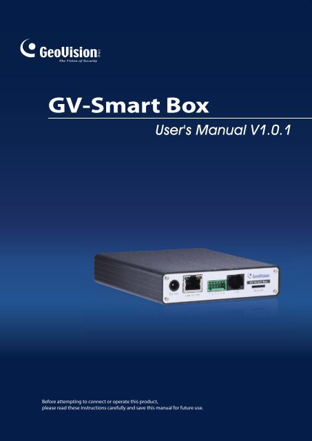
<strong>GV</strong>-<strong>Smart</strong> <strong>Box</strong>User's Manual V1.0.1Before attempting to connect or operate this product,please read these instructions carefully and save this manual for future use.
© 2011 GeoVision, Inc. All rights reserved.Under the copyright laws, this manual may not be copied, in whole or in part,without the written consent of GeoVision.Every effort has been made to ensure that the information in this manual isaccurate. GeoVision, Inc. makes no expressed or implied warranty of any kindand assumes no responsibility for errors or omissions. No liability is assumedfor incidental or consequential damages arising from the use of the informationor products contained herein. Features and specifications are subject tochange without notice.GeoVision, Inc.9F, No. 246, Sec. 1, Neihu Rd.,Neihu District, Taipei, TaiwanTel: +886-2-8797-8377Fax: +886-2-8797-8335http://www.geovision.com.twTrademarks used in this manual: GeoVision, the GeoVision logo and <strong>GV</strong>series products are trademarks of GeoVision, Inc. Windows and Windows XPare registered trademarks of Microsoft Corporation.June 2011
PrefaceWelcome to the <strong>GV</strong>-<strong>Smart</strong> <strong>Box</strong> User’s Manual.The <strong>GV</strong>-<strong>Smart</strong> <strong>Box</strong> has two models designed to meet different needs. This Manual isdesigned for the following models and firmware version:ModelFirmware Version<strong>GV</strong>-<strong>Smart</strong> <strong>Box</strong> V1 1.01<strong>GV</strong>-<strong>Smart</strong> <strong>Box</strong> V3 1.01For <strong>GV</strong>-<strong>Smart</strong> <strong>Box</strong> V1, after updating the firmware from V1.0 to V1.01, you must restore<strong>GV</strong>-<strong>Smart</strong> <strong>Box</strong> to factory default settings. Refer to 5.2 Restoring to Factory Default Settingsfor detailed instruction.i
ContentsPreface……………………………………………………………….iChapter 1 Introduction ..........................................................11.1 Key Features ............................................................................................................21.2 Packing List ..............................................................................................................21.3 System Requirements ..............................................................................................21.4 Optimal Camera Installation .....................................................................................31.5 Recognition Limitations on Face Counter.................................................................41.6 Reference for Recording Capacity of a 1GB SD Card .............................................51.7 Options .....................................................................................................................61.8 Overview...................................................................................................................71.8.1 Front View......................................................................................................71.8.2 Rear View ......................................................................................................8Chapter 2 Getting Started .....................................................92.1 Installing on a Network .............................................................................................92.2 Assigning an IP Address ........................................................................................102.3 Configuring Basic Features ....................................................................................11Chapter 3 Accessing the <strong>GV</strong>-<strong>Smart</strong> <strong>Box</strong> ...........................123.1 Accessing Your Surveillance Images .....................................................................123.2 Functions Featured on the Main Page ...................................................................133.2.1 People Counting and Face Counter.............................................................143.2.2 Network Status.............................................................................................18Chapter 4 Administrator Mode ...........................................194.1 Video and Motion....................................................................................................204.1.1 Video Settings ............................................................................................204.1.2 Detection Mode............................................................................................224.1.3 <strong>GV</strong>-<strong>Smart</strong> <strong>Box</strong> Settings ..............................................................................244.2 I/O Control ..............................................................................................................254.2.1 Input Setting ...............................................................................................254.2.2 Output Setting ............................................................................................264.3 Events & Alerts.......................................................................................................274.3.1 VSM (Vital Sign Monitor)............................................................................27ii
1IntroductionChapter 1 IntroductionThe <strong>GV</strong>-<strong>Smart</strong> <strong>Box</strong> is a standalone device designed for indoor environments such as shopsand offices. Connecting to any analog camera, the <strong>GV</strong>-<strong>Smart</strong> <strong>Box</strong> counts the number ofvisitors or faces. Having this data not only helps you keep an eye on your properties, but alsohelps retailers identify peak traffic hours, providing valuable information for making strategicdecisions.Without installing any software, you can easily access the live images and counting data ofthe <strong>GV</strong>-<strong>Smart</strong> <strong>Box</strong> from anywhere in the world through a computer using the IE browser. Youcan also integrate the <strong>GV</strong>-<strong>Smart</strong> <strong>Box</strong> with <strong>GV</strong> applications such as <strong>GV</strong>-Web Report,<strong>GV</strong>-System and <strong>GV</strong>-Compact DVR to support extended functionality.<strong>GV</strong>-<strong>Smart</strong> <strong>Box</strong>Live Images, People Counting and FaceCounting ResultsNetworkUser 1(IE browser)User 20(IE browser)Figure 1-11
1.1 Key Features• Counts the number of visitors• Counts the number of faces• Easily accessible Web-based interface to watch live views, query database, andcustomize settings• Triggers alarm when faces covered with masks are detected• Supports UMTS• Integrates with <strong>GV</strong>-Web Report, <strong>GV</strong>-System or <strong>GV</strong>-Compact DVR• Connects to VSM and sends alerts in the event of I/O trigger, video lost and networkdisconnection• Supports adjustment of video attributes• Sets detection mode by schedule1.2 Packing List1. <strong>GV</strong>-<strong>Smart</strong> <strong>Box</strong> x 12. I/O Cable with RJ-45 Connector x 13. Power Adaptor x 14. Wall Hook x 15. Conical Anchor x 46. Screw x 47. <strong>GV</strong>-<strong>Smart</strong> <strong>Box</strong> Software DVD x 18. <strong>GV</strong>-<strong>Smart</strong> <strong>Box</strong> User’s Manual on Software DVD1.3 System RequirementsThese are the requirements for the computer that displays the image or controls the<strong>GV</strong>-<strong>Smart</strong> <strong>Box</strong>.• OS: 32-bit Windows XP / Vista / 7 / Server 2008; 64-bit Windows 7 / Server 2008• Web Browser: Internet Explorer 7.0 or later2
1Introduction1.4 Optimal Camera InstallationTo get the optimal results for the People Counting and Face Counter function, follow theinstructions below to install the camera.People Counting:• The camera should be installed to the ceiling at least 2.5 meters above the floor. Thecamera should face straight down.• Position the camera in the middle of the two defined detection zones so that the systemcan easily identify people when they pass through.Positioning the camera in the middle of twodefined detection zones.• Don’t install the camera in such an angle that the size of people varies dramatically in thecamera view.• Make sure that no doors or any items are ever crossing the middle line where the camerais installed. If a door is opened towards the camera, place the camera further away fromthe door.• Avoid placing the camera where it can be subjected to direct sunlight or reflections. Ifsharp shadow edges are visible in the camera view, the count accuracy might be less thanwhat it normally is.• If the camera has the Auto Gain Control (AGC) and Auto White Balance (AWB) features,disable them.3
Face Counter:• Install the camera inside an entrance pointing horizontally outward. The face countingfunction is designed to detect front-view faces only.• Avoid installing the camera where it can be subjected to direct sunlight or reflections. Thelighting of the entrance where you set the camera should be sufficient but not be too brightor dark. Light should be distributed evenly across faces without too much light comingfrom one side. If sharp shadow edges are visible in the camera view, the count accuracymight be less than what it normally is.1.5 Recognition Limitations on Face Counter• Recognition Angle: Front face only (side face cannot be recognized)• Face with Mask Filter: Not recommended for people with long beard or mustache• Recognition Area Range: The area of the detected face must take up 10% to 50% ofcamera view4
1Introduction1.6 Reference for Recording Capacity of a 1GB SD CardFor Face Counter function, a SD card with 1GB capacity can store approximately 40,000 logevents (both MDB and images) at D1 resolution, and 97,000 log events at CIF resolution. ForPeople Counting function, a SD card with 1GB capacity can store approximately 52,000 logevents at D1 resolution, and 122,000 log events at CIF resolution.FunctionPeople Counting CIF: 122,000Face CounterCIF: 97,000People CountingD1: 52,000Face CounterD1: 40,000Log Events(MDB and Images)5
1.7 OptionsOptional <strong>GV</strong> applications can expand your <strong>GV</strong>-<strong>Smart</strong> <strong>Box</strong>’s capabilities and versatility.Contact your dealer for more information. For details on connecting to optional devices, seeChapter 7.Through the Web browser, the <strong>GV</strong>-Web Report keeps track of andanalyzes the people counting and face counting results from multiple<strong>GV</strong>-<strong>Smart</strong> <strong>Box</strong>es. The integration brings you the following benefits:<strong>GV</strong>-Web Report• Live view display from <strong>GV</strong>-<strong>Smart</strong> <strong>Box</strong>es• Data analysis of people counts and face countsCompatible version: V2.0 or later<strong>GV</strong>-SystemGeoVision Analog and Digital Video Recording Software. In most ofdocuments, the <strong>GV</strong>-System also refers to Multicam System, <strong>GV</strong>-NVR System and <strong>GV</strong>-Hybrid DVR System at the same time. Theintegration brings you the following benefits:• Live view display from <strong>GV</strong>-<strong>Smart</strong> <strong>Box</strong>es• People counting results overlaid on the live imagesCompatible version: V8.34 or later<strong>GV</strong>-Compact DVRThe <strong>GV</strong>-Compact DVR is a mobile video recorder. The integration bringsyou the following benefit.• People counting results overlaid on the live imagesCompatible version: V1.03 or later6
1Introduction1.8 OverviewThis section identifies the various components of the <strong>GV</strong>-<strong>Smart</strong> <strong>Box</strong>.1.8.1 Front View1 2 3456Figure 1-2No. NameFunction1 Power LED Indicates the power is supplied.2 Ready LED Indicates the unit is ready for connection.3 Default ButtonIt resets all configurations to their factory settings. See 5.2 Restoringto Factory Default Settings.4 USB Port Connects a UMTS modem. See 4.5.2 UMTS.5 Video In Connects a camera.6 TV-OutConnects an external monitor to output live videos and peoplecounting and face counting results immediately. It is useful when youcannot access the <strong>GV</strong>-<strong>Smart</strong> <strong>Box</strong> through the network. For detailson setting the TV-Out function, see “TV OUTPUT Port Setting” in4.1.1 Video Settings.7
1.8.2 Rear ViewFigure 1-3No. NameFunction1 DC 12V Connects the supplied power adaptor.2 Ethernet Port Connects a 10/100 Ethernet network.3 Terminal Block Not functional.4 I/O Port5 Mini SD Card Slot6 Micro SD Card SlotA port for digital inputs and relay outputs. Insert the suppliedI/O Cable with RJ-45 Connector to this port. See Chapter 6The I/O Terminal Block.Note: Wiegand interface is NOT functional now.Inserts a Mini Secure Digital (SD) card. The Mini SD card isused for storing log data and images.Inserts a Micro Secure Digital (SD) card. The Micro SD card isused for storing log data and images.8
2Getting StartedChapter 2 Getting StartedThis section provides basic information to get the <strong>GV</strong>-<strong>Smart</strong> <strong>Box</strong> working on the network.2.1 Installing on a NetworkThese instructions describe the basic connections to install the <strong>GV</strong>-<strong>Smart</strong> <strong>Box</strong> on the network.Figure 2-11. Connect the video output of your camera to the BNC video input.2. Connect the hub or switch on the LAN to the unit’s 10/100 Mbps Ethernet port.3. Connect the power supply to the power input.4. Wait until both Power and Ready LEDs are on. Then you can set the IP address for theunit.9
2.2 Assigning an IP AddressDesigned for use on an Ethernet network, the <strong>GV</strong>-<strong>Smart</strong> <strong>Box</strong> must be assigned an IP addressto make it accessible.Note: The <strong>GV</strong>-<strong>Smart</strong> <strong>Box</strong> has a default address of 192.168.0.230. The computer used toset the IP address must be under the same IP and subnet sequence assigned to the unit.1. Open your Web browser, and type the default IP address http://192.168.0.230/.2. In both Login and Password fields, type the default value admin. Click Apply.3. In the left menu, select Network and then LAN to begin the network settings.Figure 2-24. Select Static IP address. Type IP Address, Subnet Mask, Router/Gateway, Primary DNSand Secondary DNS in the Configure connection parameters section.5. Click Apply. The <strong>GV</strong>-<strong>Smart</strong> <strong>Box</strong> is accessible by entering the assigned IP address on theWeb browser.10
Chapter 3 Accessing the <strong>GV</strong>-<strong>Smart</strong><strong>Box</strong>Two types of users are allowed to log in the <strong>GV</strong>-<strong>Smart</strong> <strong>Box</strong>: Administrator and Guest. TheAdministrator has unrestricted access to all system configurations, while the Guest has theaccess to live view and network status configurations only.Note: To access the Web interface of <strong>GV</strong>-<strong>Smart</strong> <strong>Box</strong>, make sure the Web browser you useis Internet Explorer 7 or later.3.1 Accessing Your Surveillance ImagesOnce installed, your <strong>GV</strong>-<strong>Smart</strong> <strong>Box</strong> is accessible on the network. Follow these steps toaccess your surveillance images, people counting, and face counting results:1. Start the Internet Explorer browser.2. Enter the IP address or domain name of the <strong>GV</strong>-<strong>Smart</strong> <strong>Box</strong> in the Location/Addressfield of your browser.Figure 3-13. Enter a login name and password.• The default login name and password for Administrator are admin.• The default login name and password for Guest are guest.4. A video image, similar to the example in Figure 3-2, is now displayed in your browser.Note: To enable the updating of images in Internet Explorer, you must set your browser toallow ActiveX Controls and perform a one-time installation of GeoVision’s ActiveXcomponent onto your computer.12
3Accessing the <strong>GV</strong>-<strong>Smart</strong> <strong>Box</strong>3.2 Functions Featured on the Main PageThis section introduces the features of the Live View window and Network Status on themain page. The two features are accessible by both Administrator and Guest.Main Page of Guest Mode▼ Video and Motion► Live View▼ Network► StatusFigure 3-213
3.2.1 People Counting and Face CounterIn the Live View configuration window, the People Counting and Face Counter functions areavailable for configuration. These two functions cannot be enabled simultaneously. You canonly enable either People Counting or Face Counter at one time. The configuration of thesetwo functions is accessible by both Administrator and Guest.3.2.1.1 People CountingTo configure the <strong>GV</strong>-<strong>Smart</strong> <strong>Box</strong> to count people, click the People Counting tab.Figure 3-31. In the Definition section, there are two options:• Define Detection Zones: Use the mouse to outline detection regions on the videoimage. Number 1 indicates region 1, and number 2 indicates region 2. Definingmultiple regions 1 and 2 is practicable. Clicking will clear all defined regions.• Define Object Sizes: Use the mouse to outline a region matching the normal size ofpeople on the video image. If the video is playing, first click the Snapshot button tofreeze the image before defining.14
3Accessing the <strong>GV</strong>-<strong>Smart</strong> <strong>Box</strong>2. In the Sensitivity section, adjust the detection sensitivity by moving the slider. The higherthe value, the more sensitive the system to motion. The default value is 4.3. In the Setting section, select Enable Counting and select how you want to count thepeople.• 1 Way Counting: When a person appears in region 1 and then enters region 2, it willbe counted as 1 in.• 2 Way Counting: When a person appears in region 1 and then enters region 2, it willbe counted as 1 in, and when an object appears in region 2 and then enters region 1,it will be counted as 1 out.4. In the Reset at section, type a reset counting time between 0 and 23. For example, if youtype 23, the number of In and Out in the Counting Result section will become zero at 23o’clock daily. The daily counting data will be saved in the Mini / Micro SD card. The <strong>GV</strong>-<strong>Smart</strong> <strong>Box</strong> then starts counting In and Out numbers again.5. Click the Save button to start the People Counting function.Other Configurations available on this Web page:[Setting]• Firmware Upgrade: Upgrades the firmware of <strong>GV</strong>-<strong>Smart</strong> <strong>Box</strong> over LAN. See 5.1.1Upgrading Firmware over LAN.• Color Adjustment: Adjusts the brightness, contrast, saturation and hue of the video.[Option]• Show Objects: If you enable Show Objects, the defined masked regions will bedisplayed on the video image for your reference.Demo: Illustrates the optimal distance between the camera and object.[Counting Result] Presents the number of people in or out.• Reset Counter: Resets the number of In and Out to zero immediately. The countingdata will be saved in the Mini / Micro SD card. The <strong>GV</strong>-<strong>Smart</strong> <strong>Box</strong> then starts counting Inand Out numbers again.Note: To get the optimal people counting results, follow the instructions to install thecamera. See 1.4 Optimal Camera Installation.15
3.2.1.2 Face CounterTo configure the <strong>GV</strong>-<strong>Smart</strong> <strong>Box</strong> to count detected faces, click the Face Counter tab.Figure 3-41. In the Setting section, the following options are available:• Alarm Type: three detection alarm types are available for Face Counter:Face with Mask Filter: The alarm type needs I/O devices to work with. After theinput device is triggered, the system will start detecting faces; the output devicewill only be triggered when a face is detected within the time interval specified.For example, after a door sensor (input) is triggered, the door lock (output) willonly open if a face is detected by the system within 30 seconds.To use this function, the Administrator must install I/O devices and set up I/Otriggered settings in advance. To install I/O devices, see 4.2 I/O Control; toconfigure I/O triggered settings, see 4.1.2 Detection Mode.Face with Inverse Mask Filter: The alarm type needs I/O devices to work with.After the input device is triggered, if the system is unable to detect faces withinthe time interval specified, the output device will be triggered. For example, afteran ATM card is inserted into an ATM machine, a security alert will be sent if <strong>GV</strong>-<strong>Smart</strong> <strong>Box</strong> is unable to detect a face within 30 seconds.To use this function, the Administrator must install I/O devices and set up I/Otriggered settings in advance. To install I/O devices, see 4.2 I/O Control; toconfigure I/O triggered settings, see 4.1.2 Detection Mode.16
3Accessing the <strong>GV</strong>-<strong>Smart</strong> <strong>Box</strong>Face Only: Detects and counts faces only. When a face is detected, a greencircle will appear on the face.The Face Only detection can be activated by motion or input trigger. To use thisfunction, the Administrator must install I/O devices or set up trigger types inadvance. To install I/O devices, see 4.2 I/O Control; to configure trigger type, see4.1.2 Detection Mode.• Sensitivity: Adjust the detection sensitivity by moving the slider. The higher the value,the more sensitive the system to motion. The default value is 4.• Reset at: Type a reset counting time between 0 and 23. For example, if you type 23,the Viewer and Total numbers displayed on the bottom of the live view window willreset to 0 at 23 o’clock daily. The daily face counting data will be saved in the Mini /Micro SD card.• Show minimum face size: Shows the minimum face size that the <strong>GV</strong>-<strong>Smart</strong> <strong>Box</strong> isable to detect. For optimal results, position the camera so that the area of thedetected face takes up 10% to 50% of camera view.2. Click the Save button to start the Face Counter function.Other Configurations available on the page:[Setting]• Firmware Upgrade: Upgrades the firmware of <strong>GV</strong>-<strong>Smart</strong> <strong>Box</strong> over LAN. See 5.1.1Upgrading System Firmware over LAN.• Color Adjustment: Adjusts the brightness, contrast, saturation and hue of the video.[Reset Counter] Resets the number of Viewer and Total on the Live View windowimmediately. The counting data will be saved in the Mini / Micro SD card. The Viewerpresents the current number of detected faces on the image. The Total presents the totalnumber of detected faces. Up to 8 faces can be detected on the image at the same time.Note: To get the optimal face counting results, follow the instructions to install the camera.See 1.4 Optimal Camera Installation. For details on the limitations of Face Counterfunction, see 1.5 Recognition Limitations on Face Counter.17
3.2.2 Network StatusTo view the network status, in the left menu, click Network and select Status.Figure 3-518
4Administrator ModeChapter 4 Administrator ModeThe Administrator can access the system configuration via the Internet. Five categories ofconfigurations are included in the system configuration: Video and Motion, I/O Control,Events and Alerts, Network, and Management.▼ Video and Motion► Live View► Video Settings► Detection Mode► <strong>GV</strong>-<strong>Smart</strong> <strong>Box</strong> Settings▼ I/O Control► Input Setting► Output Setting▼ Events and Alerts► VSM► Compact DVR Setting► Web Report Setting► Inquire Database▼ Schedule► Camera 1▼ Network► Status► LAN► UMTS► Advanced TCP/IP Figure 4-1► IP Filtering▼ Management► Date and Time► Storage Settings► User Account► Log Information► Tools▼ Logout19
4.1 Video and MotionThis section introduces Video Settings and <strong>GV</strong>-<strong>Smart</strong> <strong>Box</strong> Settings (<strong>GV</strong>-System connectionsettings) that allow you to customize People Counting and Face Counter functions.4.1.1 Video SettingsFigure 4-220
4Administrator Mode[Video Signal Type] The <strong>GV</strong>-<strong>Smart</strong> <strong>Box</strong> supports both NTSC and PAL video signals. Selecteither NTSC or PAL.The live resolution is set to be 360 x 240 (NTSC) or 360 x 288 (PAL). There are severalframe rates available.NTSC 1, 3, 5, 7, 10, 15Frame RatePAL 1, 3, 5, 8, 12• Overlay Text: Enter a text message that will be overlaid on live and captured images, e.g.company name.• Overlay Time: Select this option to display the time stamp on live and captured images.• Text Alignment: Select a position for the text and time stamp to appear on live andcaptured images, e.g. down left, down right, top left or top right.[Video Saving Setting]• Save Image Size: Select the size of the captured image to be saved to the Mini / MicroSD card. There are two options: CIF and D1.[TV Output Port Setting] The <strong>GV</strong>-<strong>Smart</strong> <strong>Box</strong> allows the direct connection of an externalmonitor to output live images and counting results immediately. When the unit is installed ata place where the network is not accessible, the TV-Out port can be used for cameraadjustment to ensure the image of people or face is captured properly.• Frames per second: Select a frame rate of 1, 5 or 10 for the TV output.• Overlay System Information: Select Enable to overlay time, date, detection mode andcounting results on the live images of TV output.21
4.1.2 Detection ModeThe Detection Mode section allows you to set the <strong>GV</strong>-<strong>Smart</strong> <strong>Box</strong> to begin counting uponinput trigger or upon motion detection. When face detection fails, an output device will betriggered, for example, an alarm may be activated for warning (in Face with Inverse MaskFilter function), or a door lock may not be unlocked (in Face with Mask Filter function). Tohave the I/O application, you must set up the I/O devices on the <strong>GV</strong>-<strong>Smart</strong> <strong>Box</strong> first byreferring to 4.2.1 Input Setting.Figure 4-3[GPIO] Begins face counting upon input trigger.• Trigger Input: Select Input 1 and/or Input 2 and the <strong>GV</strong>-<strong>Smart</strong> <strong>Box</strong> will begin facedetecting after the input device is triggered. If both options are selected, face detectingwill begin after either input device is triggered.• Trigger digital output relay: Select Output 1 and/or Output 2 to trigger an output deviceif a face (in Face with Mask Filter function) or no face (in Face with Inverse Mask Filterfunction) is detected after the time interval specified below.• Trigger Period: The <strong>GV</strong>-<strong>Smart</strong> <strong>Box</strong> will attempt to detect faces for the number ofseconds specified. For example of the Face with Inverse Mask Filter function, if you setthe interval to 30 seconds, the output device will be triggered if the system cannot detectany faces within 30 seconds after the input device is triggered.Note: The GPIO function works with Face with Mask Filter, Face with Inverse MaskFilter and Face only options in Face Counter. See 3.2.1.2 Face Counter.22
4Administrator Mode[Motion] Begins people or face counting upon motion detection. The Motion-triggeredcounting option applies to the People Counting function and the Face Only option of FaceCounter function.23
4.1.3 <strong>GV</strong>-<strong>Smart</strong> <strong>Box</strong> SettingsThe <strong>GV</strong>-<strong>Smart</strong> <strong>Box</strong> can connect to the <strong>GV</strong>-System. For details on the connection, see 7.2Connecting to <strong>GV</strong>-System.Once you have connected the <strong>GV</strong>-<strong>Smart</strong> <strong>Box</strong> to the <strong>GV</strong>-System, the live images of the <strong>GV</strong>-<strong>Smart</strong> <strong>Box</strong> will be transmitted to the <strong>GV</strong>-System, and the people counting results can beoverlaid on the live images as well.Figure 4-4[Name Setting] Type a descriptive name for the <strong>GV</strong>-<strong>Smart</strong> <strong>Box</strong>.[Period of Connection Checking] Set the time interval in seconds between eachreconnection attempt.[Connection Port Settings] Both POS Port and POS ACK Port are used for transmittingthe counting results to the <strong>GV</strong>-System. The default port numbers are 4000 and 3999respectively.The Live Center Port is used for accessing the Web interface of <strong>GV</strong>-<strong>Smart</strong> <strong>Box</strong> on thebrowser. When you want to access Web interfaces of multiple units of <strong>GV</strong>-<strong>Smart</strong> <strong>Box</strong> on thesame computer, set different Live Center Ports for each <strong>GV</strong>-<strong>Smart</strong> <strong>Box</strong>; otherwise youcannot access more than one <strong>GV</strong>-<strong>Smart</strong> <strong>Box</strong> at the same time.24
4Administrator Mode4.2 I/O ControlThe I/O terminal block on the rear panel of <strong>GV</strong>-<strong>Smart</strong> <strong>Box</strong> provides the interface for digitalinputs and relay outputs. For details on the I/O terminal block, see Chapter 6.4.2.1 Input SettingThe <strong>GV</strong>-<strong>Smart</strong> <strong>Box</strong> can connect up to 2 input devices, e.g. sensors.Figure 4-5• Name: Type a descriptive name for the input device.• Normal State: Set up the input state to trigger actions by selecting Open Circuit (N/O)or Grounded Circuit (N/C).• Latch Mode: Enable this option to have a momentary output alarm.• Trigger digital output relay: Select the output(s) to be triggered after the input isactivated.25
4.2.2 Output SettingThe <strong>GV</strong>-<strong>Smart</strong> <strong>Box</strong> can connect up to 2 output devices, e.g. alarms.There are six output signals available: N/O (Open Circuit), N/C (Grounded Circuit), N/OToggle, N/C Toggle, N/O Pulse and N/C Pulse. Choose the one that best suits the deviceyou are using. For Toggle output type, the output continues to be triggered until a new inputtrigger ends the output. For Pulse output type, the output is triggered for the amount of timeyou specify in the Trigger Pulse Mode for x seconds field.Figure 4-626
4Administrator Mode4.3 Events & Alerts4.3.1 VSM (Vital Sign Monitor)The <strong>GV</strong>-<strong>Smart</strong> <strong>Box</strong> can connect to the central monitoring station VSM and VSM can receivetext alerts in the event of video lost, I/O trigger and network disconnection. To monitorthrough VSM, you must already have a subscriber account on VSM. One <strong>GV</strong>-<strong>Smart</strong> <strong>Box</strong> canconnect to up to 2 VSM centers for central monitoring.Figure 4-7To set up VSM:1. Select Activate Link to enable the function.2. Type the Host Name or IP address of the VSM server.3. Type a port number or keep the default value 5609.4. Type a valid User Name and Password to log into VSM.5. Click Apply.The Connection Status should display “Connected” and the connected time.27
4.3.2 Compact DVR SettingThe <strong>GV</strong>-<strong>Smart</strong> <strong>Box</strong> can connect to the <strong>GV</strong>-Compact DVR. For details on the connection, see7.3 Connecting to <strong>GV</strong>-Compact DVR.Type the IP address, port number, user name and password of the <strong>GV</strong>-Compact DVR.Select one channel of the <strong>GV</strong>-Compact DVR to overlay the people counting results on thechannel. The default port number is 10000.Figure 4-828
4Administrator Mode4.3.3 Web Report SettingThe <strong>GV</strong>-<strong>Smart</strong> <strong>Box</strong> can connect to the <strong>GV</strong>-Web Report. For details on the connection, see7.1 Connecting to <strong>GV</strong>-Web Report.Type the host name or IP address, port number, user name and password of the <strong>GV</strong>-WebReport and click Apply. The default port number is 30000.You can click Export all button if the network was interrupted to resend all data to the <strong>GV</strong>-Web Report.The Connection Status is shown on the bottom of the page to show whether <strong>GV</strong>-WebReport is connected and the time of connection.Figure 4-929
4.3.4 Database InquiryYou can query people counting and face counting data from the Mini / Micro SD card. Inaddition, the people counting results can be presented in statistical diagrams.Note: The log data is recorded in the Mini / Micro SD card. Make sure you have insertedthe Mini / Micro SD card into the <strong>GV</strong>-<strong>Smart</strong> <strong>Box</strong> before you query the data.Figure 4-1030
4Administrator ModeQuerying DataTo query log data of People Counting:1. Select Counter from the Event Filter.2. If you want to query log events recorded during the Daylight Saving Time period, selectDST from the DST Enable; otherwise, select Non DST.3. Select time period and click Search. This log event list appears.Figure 4-11Up to 100 log events can be listed on each page. You can click Photo to see the snapshot ofthe log event.No. Description1 Display the total number of people counted within the queried period.2 Display numbers of events.3 Display the host name of the <strong>GV</strong>-<strong>Smart</strong> <strong>Box</strong>.4 Display the time of the event.5 Display the number of people in.6 Display the number of people out.7 Click to display the snapshot of the event.31
To query log data of Face Counter:1. Select Face Counter from the Event Filter.2. If you want to query log events recorded during the Daylight Saving Time period, selectDST from the DST Enable; otherwise, select Non DST.3. Select time period and click Search. This log event list appears.Figure 4-12Up to 100 log events can be listed on each page. You can click Photo to see the snapshot ofthe log event.No. Description1 Display the total number of the detected faces within the queried period.2 Display numbers of events.3 Display the host name of the <strong>GV</strong>-<strong>Smart</strong> <strong>Box</strong>.4 Display the start time of the event.5 Display the recognition time spent on the event.6 Click to display the snapshot of the event.32
4Administrator ModeProducing Statistic DiagramsThe <strong>GV</strong>-<strong>Smart</strong> <strong>Box</strong> can present the people counting results in a diagram. You can only querythe People Counting log events on a specified date. Select the desired date and clickDisplay. The following diagram appears.You can easily see the peak time of people counting results in the statistical diagram. Thehourly numbers of people in and out are illustrated both in the diagram and the table.Figure 4-1333
4.4 ScheduleThe Schedule section allows you to set a schedule to begin counting upon motion or I/Otrigger.Figure 4-14To set up a schedule:1. Select Span 1 and select to detect upon Motion or I/O.2. Specify a time period. The period that you specify is effective from Monday throughSunday.3. To have the <strong>GV</strong>-<strong>Smart</strong> <strong>Box</strong> function all day on the weekend, select Weekend and definewhether the weekend includes Sunday & Saturday or Sunday Only.4. To enable <strong>GV</strong>-<strong>Smart</strong> <strong>Box</strong> on a specific date, select Special Day, select the detectionmode and type the date.Note: The detection mode selected in the Schedule section has priority over the settings inthe Detection Mode section. See 4.1.2 Detection Mode for details.34
4Administrator Mode4.5 NetworkThe Network section includes some basic but important network configurations that enablethe <strong>GV</strong>-<strong>Smart</strong> <strong>Box</strong> to be connected to a TCP/IP network.4.5.1 LANAccording to your network environment, select among Static IP, DHCP, PPPoE and UMTS.Figure 4-15[LAN Configuration]• Dynamic IP address: The network environment has a DHCP server. This option shouldonly be enabled if you know which IP address the <strong>GV</strong>-<strong>Smart</strong> <strong>Box</strong> will get from the DHCPserver, or you have obtained a domain name from the DDNS service provider.• Static IP address: Assign a static IP or fixed IP to the <strong>GV</strong>-<strong>Smart</strong> <strong>Box</strong>. Type TCP/IP andDNS parameters of the unit in the Configure connection parameters section.35
• PPPoE: The Network environment is xDSL connection. Type the Username andPassword provided by ISP to establish the connection. If you use the xDSL connectionwith dynamic IP addresses, you must use the DDNS function to obtain a domain namelinked to the changing IP address of the <strong>GV</strong>-<strong>Smart</strong> <strong>Box</strong> first.[Configure connection parameters] Type the IP address, Subnet Mask, Router/Gateway,Primary DNS server and Secondary DNS server of the <strong>GV</strong>-<strong>Smart</strong> <strong>Box</strong>.ParametersDefaultIP address 192.168.0.230Subnet Mask 255.255.255.0Router/Gateway 192.168.0.1Primary DNS server 192.168.0.1Secondary DNS server 192.168.0.2For details on the DDNS function (Dynamic DNS Server), see 4.5.3 Advanced TCP/IP.36
4Administrator Mode4.5.2 UMTSUMTS stands for Universal Mobile Telephone System. UMTS is a third-generation (3G)broadband, packet-based transmission of text, digitized voice, video, and multimedia at datarates up to 2 megabits per second. UMTS offers a consistent set of services to mobilecomputer and phone users, no matter where they are located in the world.After a mobile broadband device (supporting UMTS, HSDPA, etc.) is attached to the USBport on the front panel and the UMTS function is enabled, the <strong>GV</strong>-<strong>Smart</strong> <strong>Box</strong> can havewireless broadband access. For supported mobile broadband devices, see Appendix.Figure 4-1637
[UMTS Settings]• PIN Number: Type the PIN number that is provided by your network operator.• APN: Type the Access Point Name that is provided by your network operator.• Username: Type a valid username to enable the UMTS service from your networkoperator.• Password: Type a valid password to enable the UMTS service from your networkoperator.• MTU: Type the Maximum Transfer Unit. The default value is 1500.• Keep Check UMTS Connection: Select this option to check the UMTS connectionstatus and use the drop-down list to specify the desired time length for check frequency.• Check VPN Connection: Select this option to check the VPN (Virtual Private Network)connection status. To check the IP address, type the target IP address in the CheckTarget IP Address field.• UMTS Authentication Protocol: Use the drop-down list to select the UMTSAuthentication Protocol provided by your network operator.[3G Connection Status] Indicates the connection status of UMTS or VPN.38
4Administrator Mode4.5.3 Advanced TCP/IPThis section introduces the advanced TCP/IP settings, including DDNS Server and HTTPport.Figure 4-17[Dynamic DNS Server Settings] DDNS (Dynamic Domain Name System) provides aconvenient way of accessing the <strong>GV</strong>-<strong>Smart</strong> <strong>Box</strong> when using a dynamic IP. DDNS assigns adomain name to the <strong>GV</strong>-<strong>Smart</strong> <strong>Box</strong>, so that the Administrator does not need to go throughthe trouble of checking if the IP address assigned by DHCP Server or ISP (in xDSLconnection) has changed.39
Before enabling the DDNS function, the Administrator should apply for a host name from theDDNS service provider’s website. There are 2 providers listed in the <strong>GV</strong>-<strong>Smart</strong> <strong>Box</strong>:GeoVision DDNS Server and DynDNS.org.To enable the DDNS function:1. Enable: Enable the DDNS function.2. Service Provider: Select the DDNS service provider you have registered with.3. Host Name: Type the host name used to link to the <strong>GV</strong>-<strong>Smart</strong> <strong>Box</strong>. For the users ofGeoVision DDNS Server, it is unnecessary to enter the host name. The system willdetect the host name automatically.4. User Name: Type the user name used to enable the service from the DDNS.5. Password: Type the password used to enable the service from the DDNS.6. Click Apply. The Update Time from the DDNS will be displayed.[HTTP Port Settings]The HTTP port enables connecting the <strong>GV</strong>-<strong>Smart</strong> <strong>Box</strong> to the Web. For security integration,the Administrator can hide the server from the general HTTP port by changing the defaultHTTP port of 80 to a different port number within the range of 1024 through 65535.40
4Administrator Mode4.5.4 IP Filter SettingThe Administrator can set IP filtering to restrict access to the <strong>GV</strong>-<strong>Smart</strong> <strong>Box</strong>.Figure 4-18To enable the IP Filter function:1. Enable IP Filtering: Enable the IP Filtering function.2. Filtered IP: Type the IP address you want to allow or deny.3. Action to take: Select the action of Allow or Deny to be taken for the IP address youhave specified.4. Click Apply.41
4.6 ManagementThe Management section includes the settings of date and time, SD card and user account.Also you can view the firmware version and execute certain system operations.4.6.1 Date & Time SettingYou can set up the date and time appearing in the image’s caption.42Figure 4-19
4Administrator Mode[Date & Time on <strong>GV</strong>-<strong>Smart</strong> <strong>Box</strong>] Display the current date and time on the <strong>GV</strong>-<strong>Smart</strong> <strong>Box</strong>.[Time Zone] Set the time zone for local settings. Select Enable Daylight Saving Time toautomatically adjust the <strong>GV</strong>-<strong>Smart</strong> <strong>Box</strong> for daylight saving time. Type the Start Time and EndTime to enable the daylight saving function.[Synchronized with a Network Time Server] Use the NTP server to automatically updatethe date and time of the <strong>GV</strong>-<strong>Smart</strong> <strong>Box</strong> every 24 hours. Type the host name or the IPaddress of the NTP server for connection.[Synchronized with your computer or modify manually] Manually change the date andtime of the <strong>GV</strong>-<strong>Smart</strong> <strong>Box</strong>. Or, synchronize the date and time of the <strong>GV</strong>-<strong>Smart</strong> <strong>Box</strong> with thelocal computer. The default date and time setting is set to modify manually. The default dateis 2000/01/15, while the default time is 04:26:54.43
4.6.2 Storage SettingsThe <strong>GV</strong>-<strong>Smart</strong> <strong>Box</strong> V1 has one Mini SD card slot, while the <strong>GV</strong>-<strong>Smart</strong> <strong>Box</strong> V3 has one MicroSD card slot. You can store the counting results or images to the Mini / Micro SD card. Theimage is stored in the JPEG compressed format.Figure 4-20To add a Mini / Micro SD card:1. Insert a Mini / Micro SD card to the Mini / Micro SD card slot.2. Click the Refresh button to detect the Mini / Micro SD card. The total size, used size, freespace and utilization of the Mini / Micro SD card will be displayed. Note that it may takeseveral seconds for your Web browser to update the information from the Mini / Micro SDcard.3. If you like to format the Mini / Micro SD card or erase all data stored on it, click theFormat button.To remove a Mini / Micro SD card:1. Click the Remove button.2. When you are prompted to confirm the action, click Yes. The page will be refreshed andthe partition information will be cleaned.3. Remove the Mini / Micro SD card from the Mini / Micro SD card slot.Note: The captured images may be lost if you do not remove the Mini / Micro SD cardproperly.44
4Administrator Mode[Storage Settings]• Enable saving results on SD Card: Enable this option to save the counting data andimages onto the Mini / Micro SD card.• Enable recycling: If this option is checked, the system will overwrite the oldest storedfiles when the space of the Mini / Micro SD card is lower than the specified space. If thisoption is not checked, the system will stop recording when the specified space is reached.45
4.6.3 User AccountThe <strong>GV</strong>-<strong>Smart</strong> <strong>Box</strong> has two types of password protection: Guest password for restrictingunwanted users from accessing the <strong>GV</strong>-<strong>Smart</strong> <strong>Box</strong>, and Administrator password forrestricting who can enter privileged commands.Default Guest login name and password are guest. Default Administrator login name andpassword are admin.Figure 4-2146
4Administrator Mode4.6.4 Log InformationThe log contains dump data that is used by service personnel for analyzing problems.Figure 4-2247
4.6.5 ToolsThis section allows you to execute certain system operations and view the firmware version.Figure 4-23[Firmware Version] This section displays the firmware version of the <strong>GV</strong>-<strong>Smart</strong> <strong>Box</strong>.[System Settings] Clicking the Load Default button will restore the <strong>GV</strong>-<strong>Smart</strong> <strong>Box</strong> to factorydefault settings. The Ready LED on the front panel will turn off. Wait until the Ready LEDturns on and then you can re-log in the <strong>GV</strong>-<strong>Smart</strong> <strong>Box</strong>.Note: After applying default settings, you will need to configure the <strong>GV</strong>-<strong>Smart</strong> <strong>Box</strong>’snetwork settings again.[Reboot] Clicking the Reboot button will make the <strong>GV</strong>-<strong>Smart</strong> <strong>Box</strong> perform software reset.The Ready LED on the front panel will turn off. Wait until the Ready LED turns on and thenyou can re-log in the <strong>GV</strong>-<strong>Smart</strong> <strong>Box</strong>.48
5Advanced ApplicationsChapter 5 Advanced ApplicationsThis chapter introduces more advanced applications.5.1 Upgrading System FirmwareGeoVision will periodically release updated firmware on the website. The new firmware canbe simply loaded into the <strong>GV</strong>-<strong>Smart</strong> <strong>Box</strong> over LAN or by using the IP Device Utility includedin the Software DVD.Important Notes before You StartBefore you start updating the firmware, please read these important notes:1. While the firmware is being updated,A. the power supply must not be interrupted, andB. do not unplug the Ethernet cable if the cable is the source of power supply (Powerover Ethernet or PoE supported).2. Do not turn the power off for 5 minutes after the firmware is updated.3. If you use the IP Device Utility for firmware upgrade, the computer used to upgradefirmware must be under the same IP and subnet sequence of the <strong>GV</strong>-<strong>Smart</strong> <strong>Box</strong>.WARNING: Interruption of power supply during updating causes not only update failuresbut also damages to your <strong>GV</strong>-<strong>Smart</strong> <strong>Box</strong>. In this case, please contact your salesrepresentative and send your device back to GeoVision for repair.49
5.1.1 Upgrading Firmware over LAN1. In the Live View window (People Counting or Face Counter), click the FirmwareUpgrade button. This dialog box appears.Figure 5-12. Click the Browse button to locate the firmware file (.img) saved at your local computer.3. Click the Upgrade button to begin upgrading.5.1.2 Upgrading Firmware by Using the UtilityThe IP Device Utility provides a direct way to upgrade the firmware to multiple <strong>GV</strong>-<strong>Smart</strong><strong>Box</strong>es. Note the computer used to upgrade firmware must be under the same IP and subnetsequence of the <strong>GV</strong>-<strong>Smart</strong> <strong>Box</strong>.1. Insert the Software DVD, select IP Device Utility, and follow the onscreen instructions toinstall the program.50
5Advanced Applications2. Double-click the <strong>GV</strong> IP Device Utility icon created on your desktop. This dialog boxappears.Figure 5-23. Double-click one <strong>GV</strong>-<strong>Smart</strong> <strong>Box</strong> in the list. This dialog box appears.Figure 5-351
4. Click the Firmware Upgrade tab. This dialog box appears.Figure 5-45. Click the Browse button to locate the firmware file (.img) saved at your local computer.6. If you like to upgrade all the <strong>GV</strong>-<strong>Smart</strong> <strong>Box</strong>es in the list, select Upgrade all devices.7. Type Password, and click Upgrade to process the upgrade.52
5Advanced Applications5.2 Restoring to Factory Default SettingsTo restore to default settings, use the Load Default button on the front panel of <strong>GV</strong>-<strong>Smart</strong><strong>Box</strong>. See No. 3, Figure 1-2.1. Unplug and plug the power cable. The Ready LED turns off.2. Press and hold the Load Default button until the Ready LED turns on.3. Release the Load Default button. The process of loading default values is complete, andthe <strong>GV</strong>-<strong>Smart</strong> <strong>Box</strong> starts rebooting itself.Note: Before Ready LED is on again, do not unplug the power cable; otherwise theloading of default values will fail.53
Chapter 6 The I/O Terminal Block6.1 I/O Port<strong>GV</strong>-<strong>Smart</strong> <strong>Box</strong> provides the I/O Cable with RJ-45 Connector for the extensible connectionto other I/O devices. A RJ-45 connector and a bundle of shielded wires are on the each endof the cable.Strip the desired wires first, and connect the auxiliary devices with the right wires accordingto the following pin assignment. Then insert the RJ-45 Connector to the I/O Port on <strong>GV</strong>-<strong>Smart</strong> <strong>Box</strong> (No. 4, Figure 1-3).Figure 6-1Pin AssignmentThe table below lists the pin assignment for the shielded wires of the I/O Cable with RJ-45Connector.Pin WireFunction1 Brown Digital Out 12 White with Brown Stripe Digital Out 23 White with Green Stripe Ground4 White with Blue Stripe Digital In 15 Blue Digital In 26 Green Ground7 Orange Wiegand D08 White with Orange Stripe Wiegand D1Note: The Wiegand interface is NOT functional now.54
6The I/O Terminal BlockRelay OutputThe relay outputs on the terminal block can only drive a maximum load of 5 volts. Working inconjunction with the <strong>GV</strong>-Relay V2 module, it can drive heavier loads. Refer to the figure andtable below to connect the <strong>GV</strong>-Relay V2 module to the <strong>GV</strong>-<strong>Smart</strong> <strong>Box</strong>.Figure 6-2<strong>GV</strong>-Relay V2DO 1DO 2COMWireBrownWhite with Brown StripeGreenNote: The <strong>GV</strong>-Relay V2 module is an optional product.55
Chapter 7 Integration with other <strong>GV</strong>ApplicationsThe <strong>GV</strong>-<strong>Smart</strong> <strong>Box</strong> can integrate with <strong>GV</strong> applications such as <strong>GV</strong>-Web Report, <strong>GV</strong>-Systemand <strong>GV</strong>-Compact DVR for viewing live images and receiving counting results.Compatible Versions:• <strong>GV</strong>-Web Report: V2.0 or later• <strong>GV</strong>-System: V8.34 or later• <strong>GV</strong>-Compact DVR: V1.03 or laterFigure 7-156
7Integration with other <strong>GV</strong> Applications7.1 Connecting to <strong>GV</strong>-Web ReportThe integration enables the <strong>GV</strong>-Web Report to keep track of and analyze people countingand face counting results from the <strong>GV</strong>-<strong>Smart</strong> <strong>Box</strong>. To connect to the <strong>GV</strong>-Web Report, followthe steps below:1. Enable <strong>GV</strong>-Web Report function on the Web interface of the <strong>GV</strong>-<strong>Smart</strong> <strong>Box</strong> (Figure 4-9).2. Type the host name or IP address, port number, user name and password of the <strong>GV</strong>-Web Report and click Apply. The default port number is 30000.3. On the main screen of <strong>GV</strong>-Web Report, click Service and select Data Service to startreceiving data from the connected <strong>GV</strong>-<strong>Smart</strong> <strong>Box</strong>.Figure 7-24. Select Web Service (Figure 7-2) to enable the Web interface of <strong>GV</strong>-Web Report.5. Go to the Web interface of <strong>GV</strong>-Web Report. You can start accessing the live view, peoplecounting and face counting results from the <strong>GV</strong>-<strong>Smart</strong> <strong>Box</strong>.57
7.2 Connecting to <strong>GV</strong>-SystemThe integration enables the <strong>GV</strong>-System to overlay the people counting results received fromthe <strong>GV</strong>-<strong>Smart</strong> <strong>Box</strong> on the live images. To connect to the <strong>GV</strong>-System, follow the steps below:1. To configure the <strong>GV</strong>-<strong>Smart</strong> <strong>Box</strong> to connect to the <strong>GV</strong>-System, select Video and Motionand select <strong>GV</strong>-<strong>Smart</strong> <strong>Box</strong> Settings. See 4.1.3 <strong>GV</strong>-<strong>Smart</strong> <strong>Box</strong> Settings.2. To add the live view images from the <strong>GV</strong>-<strong>Smart</strong> <strong>Box</strong>, go to the main system of <strong>GV</strong>-System, click the Configure button, select General Setting, select Camera/AudioInstall and select IP Camera Install. This dialog box appears.Figure 7-33. Click Add Camera. This dialog box appears.Figure 7-458
7Integration with other <strong>GV</strong> Applications4. Type the Server IP, HTTP Port, User name and Password of the <strong>GV</strong>-<strong>Smart</strong> <strong>Box</strong>. SelectGeoVision from the Brand and <strong>GV</strong>-<strong>Smart</strong> <strong>Box</strong> (or <strong>GV</strong>-<strong>Smart</strong> <strong>Box</strong> Series) from theDevice. This dialog box appears.Figure 7-55. Click Query. After the <strong>GV</strong>-<strong>Smart</strong> <strong>Box</strong> is found, click Apply. This dialog box appears.Figure 7-66. Right-click the <strong>GV</strong>-<strong>Smart</strong> <strong>Box</strong> to select a display channel.7. To overlay the people counting results on the live images from the <strong>GV</strong>-<strong>Smart</strong> <strong>Box</strong>, go tothe main system of <strong>GV</strong>-System, select Configure, select Accessories, select POSApplication Setting, select POS Device Setup and click the New tab. This dialog boxappears.Figure 7-759
8. Select TCP/IP Port from the Printer Type, select a POS device to display peoplecounting results, select the same camera number you selected in step 6 to map liveimages and counting results together from the <strong>GV</strong>-<strong>Smart</strong> <strong>Box</strong>, select General from thePOS Module and click Data Capture IP Address Setting. This dialog box appears.Figure 7-89. Type the IP address of the <strong>GV</strong>-<strong>Smart</strong> <strong>Box</strong>. The default value of Device Port is 4000.Click OK. The people counting results are now displayed on the specified camerachannel.10. To view the people counting results displayed on the POS Live View window, go to themain system of the <strong>GV</strong>-System, select View Log and select POS Live View.Figure 7-960
7Integration with other <strong>GV</strong> Applications7.3 Connecting to <strong>GV</strong>-Compact DVRThe integration enables the <strong>GV</strong>-Compact DVR to overlay the people counting results fromthe <strong>GV</strong>-<strong>Smart</strong> <strong>Box</strong> on the live images of <strong>GV</strong>-Compact DVR. To connect to the <strong>GV</strong>-CompactDVR, follow the steps below:Note: You can not access live images from the <strong>GV</strong>-<strong>Smart</strong> <strong>Box</strong> in the integration with the<strong>GV</strong>-Compact DVR.1. Enable <strong>GV</strong>-Compact DVR Settings on the Web interface of <strong>GV</strong>-<strong>Smart</strong> <strong>Box</strong> (Figure 4-8).2. Open the OSD menu of the <strong>GV</strong>-Compact DVR, select ADVANCED, select DISPLAYSETTINGS, select INFO DISPLAY SETTING and select <strong>GV</strong>-SMART BOX INFO. Thisdialog box appears.Figure 7-103. Select a position for the recognition results to appear on the live view. POSITION 1 refersto the area below the camera name. POSITION 2 refers to the top of the live image.POSITION 3 refers to the area above camera name. HIDE refers to hiding the text on thelive image.61
Specifications<strong>GV</strong>-<strong>Smart</strong> <strong>Box</strong> V1<strong>GV</strong>-<strong>Smart</strong> <strong>Box</strong> V3Video CompressionVideo ResolutionJPEGCIFFrame RateNTSC 15PAL 12ConnectorsVideoEthernetUSBTV-Out1 input (BNC port)RJ-45, 10 / 100 Mbps1 USB 2.0 (only for UMTS)1 output (BNC port)LocalStorageMini-SD/SDHC memory cardslotMicro-SD/SDHC memory cardslotI/O Port2 sensor inputs, 2 alarm outputsOperation Temperature -20°C ~ 60°C / -4°F ~ 140°F -20°C ~ 55°C / -4°F ~ 131°FDimensions (L x W x H)PowerWeight123 x 106 x 25 mm / 4.84 x 4.17 x 0.98 inDC 12V, 1A, 50~60 Hz0.345 kg / 0.76 lbs62
AppendixAppendixSupported Mobile Broadband DeviceVendorHUAWEIVerizonVodafoneNovatelModelE169, E220, E1692, E1750, EC169C USB Modem(HSDPA/UMTS/EDGE/GPRS/GSM)U727, U760 USB Modem (EVDO)K3565-Rev2MC950D (HSDPA/UMTS/EDGE/GPRS/GSM)63