2711P-UM001F-EN-P, PanelView Plus Terminals User Manual
2711P-UM001F-EN-P, PanelView Plus Terminals User Manual
2711P-UM001F-EN-P, PanelView Plus Terminals User Manual

Create successful ePaper yourself
Turn your PDF publications into a flip-book with our unique Google optimized e-Paper software.
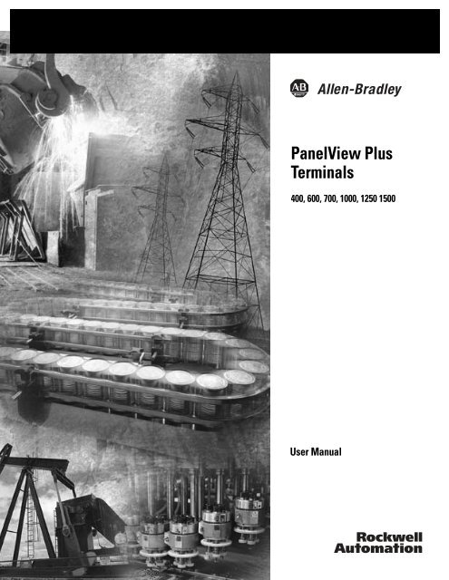
<strong>PanelView</strong> <strong>Plus</strong><br />
<strong>Terminals</strong><br />
400, 600, 700, 1000, 1250 1500<br />
<strong>User</strong> <strong>Manual</strong>
Important <strong>User</strong> Information Solid state equipment has operational characteristics differing from those of<br />
electromechanical equipment. Safety Guidelines for the Application,<br />
Installation and Maintenance of Solid State Controls (publication SGI-1.1<br />
available from your local Rockwell Automation sales office or online at<br />
http://literature.rockwellautomation.com) describes some important<br />
differences between solid state equipment and hard-wired electromechanical<br />
devices. Because of this difference, and also because of the wide variety of<br />
uses for solid state equipment, all persons responsible for applying this<br />
equipment must satisfy themselves that each intended application of this<br />
equipment is acceptable.<br />
In no event will Rockwell Automation, Inc. be responsible or liable for<br />
indirect or consequential damages resulting from the use or application of<br />
this equipment.<br />
The examples and diagrams in this manual are included solely for illustrative<br />
purposes. Because of the many variables and requirements associated with<br />
any particular installation, Rockwell Automation, Inc. cannot assume<br />
responsibility or liability for actual use based on the examples and diagrams.<br />
No patent liability is assumed by Rockwell Automation, Inc. with respect to<br />
use of information, circuits, equipment, or software described in this manual.<br />
Reproduction of the contents of this manual, in whole or in part, without<br />
written permission of Rockwell Automation, Inc., is prohibited.<br />
Throughout this manual, when necessary, we use notes to make you aware<br />
of safety considerations.<br />
WARNING<br />
IMPORTANT<br />
ATT<strong>EN</strong>TION<br />
SHOCK HAZARD<br />
BURN HAZARD<br />
Identifies information about practices or circumstances that can cause<br />
an explosion in a hazardous environment, which may lead to personal<br />
injury or death, property damage, or economic loss.<br />
Identifies information that is critical for successful application and<br />
understanding of the product.<br />
Identifies information about practices or circumstances that can lead<br />
to personal injury or death, property damage, or economic loss.<br />
Attentions help you identify a hazard, avoid a hazard, and recognize<br />
the consequence.<br />
Labels may be on or inside the equipment, for example, drive or motor,<br />
to alert people that dangerous voltage may be present.<br />
Labels may be on or inside the equipment (for example, drive or motor)<br />
to alert people that surfaces may reach dangerous temperatures.<br />
Allen-Bradley, CompactLogix, ControlLogix, DH+, FlexLogix, Logix, MicroLogix, <strong>PanelView</strong> <strong>Plus</strong>, PLC-5, RSLinx, RSLinx<br />
Enterprise, RSLogix, RSView ME, RSView Machine Edition, RSView ME Station, RSView Studio, Rockwell Automation, RSNetWorx<br />
for ControlNet, RSView32, SLC, SLC 5/03, SoftLogix, and TechConnect are trademarks of Rockwell Automation, Inc.<br />
Trademarks not belonging to Rockwell Automation are property of their respective companies.
Summary of Changes<br />
The information below summarizes the changes to this manual since<br />
the last revision.<br />
This manual now includes information for both <strong>PanelView</strong> <strong>Plus</strong> and<br />
<strong>PanelView</strong> <strong>Plus</strong> CE terminals.<br />
• <strong>Terminals</strong> previously named VersaView CE terminals are now<br />
named <strong>PanelView</strong> <strong>Plus</strong> CE terminals.<br />
• Any reference to VersaView CE in text or images is synonymous<br />
with <strong>PanelView</strong> <strong>Plus</strong> CE.<br />
• Any reference to <strong>PanelView</strong> <strong>Plus</strong> 700 to 1500 terminals also<br />
includes <strong>PanelView</strong> <strong>Plus</strong> CE terminals.<br />
Revision bars, as shown in the margin, identify updated information.<br />
Changes for this version of the document include.<br />
Topic Page<br />
Updated parts list for <strong>PanelView</strong> <strong>Plus</strong> CE terminals. 9<br />
Added software support for <strong>PanelView</strong> <strong>Plus</strong> CE terminals. 11<br />
Updated logic module information for <strong>PanelView</strong> <strong>Plus</strong> CE<br />
terminals.<br />
19<br />
Updated catalog number configuration. 22<br />
Updated product components. 22<br />
Added instructions on how to enter Configuration mode on a<br />
<strong>PanelView</strong> <strong>Plus</strong> CE terminal.<br />
57<br />
Startup shortcuts for <strong>PanelView</strong> <strong>Plus</strong> CE terminals. 92<br />
Information on the Windows CE operating system. 109<br />
Updated information and procedures for replacing the<br />
backlight.<br />
155<br />
The Remote I/O and DH+ connectors for the <strong>PanelView</strong> <strong>Plus</strong><br />
400 and 600 terminals was updated.<br />
174<br />
Information on transferring files and creating an ActiveSync<br />
connection on <strong>PanelView</strong> <strong>Plus</strong> CE terminals.<br />
189<br />
Information on upgrading the CE operating system. 202<br />
Updated troubleshooting information for <strong>PanelView</strong> <strong>Plus</strong> CE<br />
terminals.<br />
207…221<br />
3 Publication <strong>2711P</strong>-<strong>UM001F</strong>-<strong>EN</strong>-P - March 2007
Summary of Changes 4<br />
Publication <strong>2711P</strong>-<strong>UM001F</strong>-<strong>EN</strong>-P - March 2007
Table of Contents<br />
Preface Objectives. . . . . . . . . . . . . . . . . . . . . . . . . . . . . . . . . . . . . . . 9<br />
Intended Audience . . . . . . . . . . . . . . . . . . . . . . . . . . . . . . . . 9<br />
Parts List. . . . . . . . . . . . . . . . . . . . . . . . . . . . . . . . . . . . . . . . 9<br />
Additional Resources. . . . . . . . . . . . . . . . . . . . . . . . . . . . . . 10<br />
Software and Firmware Upgrades . . . . . . . . . . . . . . . . . . . . 10<br />
Chapter 1<br />
Overview Chapter Objectives . . . . . . . . . . . . . . . . . . . . . . . . . . . . . . . 11<br />
Software Support . . . . . . . . . . . . . . . . . . . . . . . . . . . . . . . . 11<br />
<strong>PanelView</strong> <strong>Plus</strong> 400 and 600 <strong>Terminals</strong> . . . . . . . . . . . . . . . . 12<br />
<strong>PanelView</strong> <strong>Plus</strong> 700 to 1500 <strong>Terminals</strong> . . . . . . . . . . . . . . . . . 17<br />
Catalog Number Configuration. . . . . . . . . . . . . . . . . . . . . . . 22<br />
<strong>PanelView</strong> <strong>Plus</strong> Product Components. . . . . . . . . . . . . . . . . . 22<br />
Chapter 2<br />
Installation Chapter Objectives . . . . . . . . . . . . . . . . . . . . . . . . . . . . . . . 29<br />
Hazardous Locations . . . . . . . . . . . . . . . . . . . . . . . . . . . . . . 29<br />
Environment and Enclosure. . . . . . . . . . . . . . . . . . . . . . . . . 32<br />
Outdoor Installation for High-bright Displays . . . . . . . . . . . . 32<br />
Required Tools . . . . . . . . . . . . . . . . . . . . . . . . . . . . . . . . . . 33<br />
Clearances . . . . . . . . . . . . . . . . . . . . . . . . . . . . . . . . . . . . . 34<br />
Cutout Dimensions . . . . . . . . . . . . . . . . . . . . . . . . . . . . . . . 34<br />
Mount the 400 or 600 Terminal in a Panel . . . . . . . . . . . . . . 34<br />
Mount the 700 to 1500 Terminal in a Panel . . . . . . . . . . . . . 37<br />
Product Dimensions . . . . . . . . . . . . . . . . . . . . . . . . . . . . . . 39<br />
Chapter 3<br />
Power Connections Chapter Objectives . . . . . . . . . . . . . . . . . . . . . . . . . . . . . . . 45<br />
Wiring and Safety Guidelines. . . . . . . . . . . . . . . . . . . . . . . . 45<br />
Remove and Install the Power Terminal Block . . . . . . . . . . . 46<br />
DC Power Connections . . . . . . . . . . . . . . . . . . . . . . . . . . . . 49<br />
AC Power Connections . . . . . . . . . . . . . . . . . . . . . . . . . . . . 52<br />
Reset the <strong>Terminals</strong>. . . . . . . . . . . . . . . . . . . . . . . . . . . . . . . 55<br />
Chapter 4<br />
Configuration Mode Chapter Objectives . . . . . . . . . . . . . . . . . . . . . . . . . . . . . . . 57<br />
Access Configuration Mode . . . . . . . . . . . . . . . . . . . . . . . . . 57<br />
Load an Application . . . . . . . . . . . . . . . . . . . . . . . . . . . . . . 61<br />
Run an Application . . . . . . . . . . . . . . . . . . . . . . . . . . . . . . . 62<br />
Application Settings. . . . . . . . . . . . . . . . . . . . . . . . . . . . . . . 62<br />
Terminal Settings . . . . . . . . . . . . . . . . . . . . . . . . . . . . . . . . 62<br />
Configure Communications . . . . . . . . . . . . . . . . . . . . . . . . . 63<br />
Configure Network Information . . . . . . . . . . . . . . . . . . . . . . 68<br />
Configure Diagnostics . . . . . . . . . . . . . . . . . . . . . . . . . . . . . 72<br />
Manage Files on the Terminal . . . . . . . . . . . . . . . . . . . . . . . 74<br />
5 Publication <strong>2711P</strong>-<strong>UM001F</strong>-<strong>EN</strong>-P - March 2007
6 Table of Contents<br />
Windows CE .NET Operating<br />
System<br />
Publication <strong>2711P</strong>-<strong>UM001F</strong>-<strong>EN</strong>-P - March 2007<br />
Modify Display Settings . . . . . . . . . . . . . . . . . . . . . . . . . . . . 77<br />
Font Linking . . . . . . . . . . . . . . . . . . . . . . . . . . . . . . . . . . . . 81<br />
Configure Keypad, Keyboard, or Mouse. . . . . . . . . . . . . . . . 82<br />
Configure the Touch Screen . . . . . . . . . . . . . . . . . . . . . . . . 84<br />
Configure Print Options. . . . . . . . . . . . . . . . . . . . . . . . . . . . 87<br />
Configure Startup Options . . . . . . . . . . . . . . . . . . . . . . . . . . 89<br />
Configure Startup Tests . . . . . . . . . . . . . . . . . . . . . . . . . . . . 95<br />
View and Clear the System Event Log . . . . . . . . . . . . . . . . . 97<br />
Display Terminal Information . . . . . . . . . . . . . . . . . . . . . . . 98<br />
Display RSView ME Station Information . . . . . . . . . . . . . . . 100<br />
Modify the Date, Time, or Time Zone . . . . . . . . . . . . . . . . 101<br />
Modify Regional Settings . . . . . . . . . . . . . . . . . . . . . . . . . . 104<br />
Chapter 5<br />
Chapter Objectives . . . . . . . . . . . . . . . . . . . . . . . . . . . . . . 109<br />
Windows CE .NET Architecture . . . . . . . . . . . . . . . . . . . . . 109<br />
Windows CE .NET Programs . . . . . . . . . . . . . . . . . . . . . . 110<br />
Windows CE .NET Operating System . . . . . . . . . . . . . . . . . 111<br />
<strong>PanelView</strong> <strong>Plus</strong> CE Memory. . . . . . . . . . . . . . . . . . . . . . . . 115<br />
Control Panel Applications . . . . . . . . . . . . . . . . . . . . . . . . 117<br />
Chapter 6<br />
Install and Replace Components Chapter Objectives . . . . . . . . . . . . . . . . . . . . . . . . . . . . . . 137<br />
Required Tools . . . . . . . . . . . . . . . . . . . . . . . . . . . . . . . . . 137<br />
Precautions. . . . . . . . . . . . . . . . . . . . . . . . . . . . . . . . . . . . 137<br />
Compatibility of Terminal Components . . . . . . . . . . . . . . . 138<br />
Install RAM or Internal CompactFlash. . . . . . . . . . . . . . . . . 141<br />
Install or Replace the Logic Module . . . . . . . . . . . . . . . . . . 142<br />
Install or Replace a Communication Module. . . . . . . . . . . . 144<br />
Replace the Display Module . . . . . . . . . . . . . . . . . . . . . . . 148<br />
Replace the Battery . . . . . . . . . . . . . . . . . . . . . . . . . . . . . . 150<br />
Replace the Bezel . . . . . . . . . . . . . . . . . . . . . . . . . . . . . . . 152<br />
Replace the Backlight . . . . . . . . . . . . . . . . . . . . . . . . . . . . 155<br />
Remove the Product ID Label . . . . . . . . . . . . . . . . . . . . . . 158<br />
Replace the Keypad Legend Inserts . . . . . . . . . . . . . . . . . . 159<br />
Use an External CompactFlash Card. . . . . . . . . . . . . . . . . . 161<br />
Chapter 7<br />
Terminal Connections Chapter Objectives . . . . . . . . . . . . . . . . . . . . . . . . . . . . . . 163<br />
Wiring and Safety Guidelines. . . . . . . . . . . . . . . . . . . . . . . 163<br />
Logic Controller Cable Charts . . . . . . . . . . . . . . . . . . . . . . 164<br />
Communication Port Isolation . . . . . . . . . . . . . . . . . . . . . . 167<br />
USB Ports . . . . . . . . . . . . . . . . . . . . . . . . . . . . . . . . . . . . . 168<br />
Serial Connections. . . . . . . . . . . . . . . . . . . . . . . . . . . . . . . 169<br />
Ethernet Connections . . . . . . . . . . . . . . . . . . . . . . . . . . . . 172
Table of Contents 7<br />
DH-485/DH+/Remote I/O Module . . . . . . . . . . . . . . . . . . . 174<br />
ControlNet Module . . . . . . . . . . . . . . . . . . . . . . . . . . . . . . 180<br />
DeviceNet Module . . . . . . . . . . . . . . . . . . . . . . . . . . . . . . 183<br />
Chapter 8<br />
Upgrade Firmware Chapter Objectives . . . . . . . . . . . . . . . . . . . . . . . . . . . . . . 189<br />
Transfer Applications . . . . . . . . . . . . . . . . . . . . . . . . . . . . 189<br />
Create an ActiveSync Connection. . . . . . . . . . . . . . . . . . . . 189<br />
Firmware Upgrade Wizard. . . . . . . . . . . . . . . . . . . . . . . . . 191<br />
Upgrade Firmware with a CompactFlash Card . . . . . . . . . . 192<br />
Upgrade Firmware with a Network (Ethernet) Connection . 196<br />
Upgrade the Operating System (OS) . . . . . . . . . . . . . . . . . 202<br />
Chapter 9<br />
Troubleshoot the System Chapter Objectives . . . . . . . . . . . . . . . . . . . . . . . . . . . . . . 205<br />
LED Indicators . . . . . . . . . . . . . . . . . . . . . . . . . . . . . . . . . 205<br />
Isolate the Problem . . . . . . . . . . . . . . . . . . . . . . . . . . . . . . 206<br />
Startup Information Messages . . . . . . . . . . . . . . . . . . . . . . 209<br />
Startup Sequence . . . . . . . . . . . . . . . . . . . . . . . . . . . . . . . 210<br />
Startup Error Messages . . . . . . . . . . . . . . . . . . . . . . . . . . . 211<br />
Check Terminal Components. . . . . . . . . . . . . . . . . . . . . . . 212<br />
Ethernet Connnection . . . . . . . . . . . . . . . . . . . . . . . . . . . . 217<br />
Application Does Not Run. . . . . . . . . . . . . . . . . . . . . . . . . 218<br />
Configuration Mode Access . . . . . . . . . . . . . . . . . . . . . . . . 218<br />
File System Errors . . . . . . . . . . . . . . . . . . . . . . . . . . . . . . . 218<br />
Advanced Diagnostics for CE <strong>Terminals</strong> . . . . . . . . . . . . . . . 219<br />
System Identification Errors . . . . . . . . . . . . . . . . . . . . . . . . 220<br />
Restart in Safe Mode . . . . . . . . . . . . . . . . . . . . . . . . . . . . . 221<br />
Clean the Display Window . . . . . . . . . . . . . . . . . . . . . . . . 222<br />
Index<br />
Appendix A - Specifications<br />
Appendix B - Compatible USB Devices<br />
Appendix C - Available Fonts for Terminal Applications<br />
Appendix D - Programmable Key Definitions<br />
Appendix E - Security Considerations<br />
Publication <strong>2711P</strong>-<strong>UM001F</strong>-<strong>EN</strong>-P - March 2007
8 Table of Contents<br />
Publication <strong>2711P</strong>-<strong>UM001F</strong>-<strong>EN</strong>-P - March 2007
Objectives<br />
Intended Audience<br />
Parts List<br />
This preface provides information on these topics.<br />
• Intended audience<br />
• Parts List<br />
• Additional resources<br />
• Software and firmware upgrades<br />
Preface<br />
Use this manual if you are responsible for installing, operating, or<br />
troubleshooting the <strong>PanelView</strong> <strong>Plus</strong> or <strong>PanelView</strong> <strong>Plus</strong> CE terminals.<br />
No special knowledge is required to understand this manual or<br />
operate the terminal. However, you must understand the functions<br />
and operations of RSView Machine Edition applications that will run<br />
on the terminal. Consult the application designer for this information.<br />
Equipment installers must be familiar with standard panel installation<br />
techniques.<br />
The <strong>PanelView</strong> <strong>Plus</strong> terminals ship with these items.<br />
• Power terminal block<br />
• RSView Machine Edition runtime software, preloaded<br />
• Mounting levers for 400 and 600 terminals, quantity eight<br />
• Mounting clips for 700 to 1500 terminals, quantity four to eight<br />
• Installation instructions<br />
• Panel cutout template<br />
Additional items ship with the <strong>PanelView</strong> <strong>Plus</strong> CE terminals.<br />
• Windows CE .NET operating system preloaded with Terminal<br />
Services and Internet Explorer<br />
• <strong>PanelView</strong> <strong>Plus</strong> CE Accessory CD with utilities and software<br />
development kit for C++.<br />
• Microsoft Windows CE license agreement<br />
9 Publication <strong>2711P</strong>-<strong>UM001F</strong>-<strong>EN</strong>-P - March 2007
10 Preface<br />
Additional Resources<br />
Software and Firmware<br />
Upgrades<br />
Publication <strong>2711P</strong>-<strong>UM001F</strong>-<strong>EN</strong>-P - March 2007<br />
For additional information, refer to these publications, that you can<br />
download from:<br />
http://literature.rockwellautomation.com.<br />
Resource Description<br />
DeviceNet Communications for <strong>PanelView</strong> <strong>Plus</strong><br />
<strong>Terminals</strong> <strong>User</strong> <strong>Manual</strong>, publication<br />
<strong>2711P</strong>-UM004<br />
ControlNet Communications for <strong>PanelView</strong> <strong>Plus</strong><br />
<strong>Terminals</strong> <strong>User</strong> <strong>Manual</strong>, publication<br />
<strong>2711P</strong>-UM003<br />
Modbus Applications for <strong>PanelView</strong> <strong>Plus</strong><br />
<strong>Terminals</strong> <strong>User</strong> <strong>Manual</strong>, publication<br />
<strong>2711P</strong>-UM002<br />
Wiring and Grounding Guidelines for <strong>PanelView</strong><br />
<strong>Plus</strong> Devices Technical Data, publication<br />
<strong>2711P</strong>-TD001<br />
Software Development Kit for <strong>PanelView</strong> <strong>Plus</strong><br />
CE <strong>Terminals</strong> <strong>User</strong> <strong>Manual</strong>, publication<br />
<strong>2711P</strong>-UM005<br />
Provides procedures for creating a<br />
DeviceNet application to run on a<br />
<strong>PanelView</strong> <strong>Plus</strong> terminal.<br />
Provides procedures for creating a<br />
ControlNet application to run on a<br />
<strong>PanelView</strong> <strong>Plus</strong> terminal.<br />
Provides procedures for creating a<br />
Modbus application to run on a<br />
<strong>PanelView</strong> <strong>Plus</strong> terminal.<br />
Provides grounding and wiring<br />
guidelines for <strong>PanelView</strong> <strong>Plus</strong> terminals.<br />
Provides information for programmers<br />
to develop CE applications for<br />
<strong>PanelView</strong> <strong>Plus</strong> CE terminals.<br />
You may also want to refer to:<br />
• online help for RSView Studio or RSLinx software.<br />
• documentation for your controller.<br />
To receive software updates (software serial number required) and<br />
firmware upgrades for your terminal:<br />
• call your local Rockwell Automation sales office or distributor.<br />
• access http://support.rockwellautomation.com.
Chapter Objectives<br />
Software Support<br />
Overview<br />
Chapter 1<br />
This chapter gives an overview of the <strong>PanelView</strong> <strong>Plus</strong> terminals.<br />
• Software support<br />
• <strong>PanelView</strong> <strong>Plus</strong> 400 and 600 features<br />
• <strong>PanelView</strong> <strong>Plus</strong> 700 to 1500 features<br />
• Catalog number configuration<br />
• Product components<br />
RSView Machine Edition runtime software is included with all<br />
<strong>PanelView</strong> <strong>Plus</strong> and <strong>PanelView</strong> <strong>Plus</strong> CE terminals. This software<br />
provides runtime and terminal configuration software for the terminals<br />
and does not require activation.<br />
You use RSView Studio software on a personal computer to create<br />
applications that run in the terminals. This software is purchased<br />
separately.<br />
The open Windows CE.NET environment of the <strong>PanelView</strong> <strong>Plus</strong> CE<br />
terminals provides:<br />
• familiar Windows desktop and user interface.<br />
• terminal server-client support to configured servers<br />
• Internet Explorer web browser.<br />
• software development kit to support custom C++ applications<br />
for Windows CE.NET operating system.<br />
• third-party device support for Windows CE.NET operating<br />
system.<br />
• Windows CE.NET operating system provides the following<br />
programs:<br />
– File viewers for MS Office: Excel, Word, PowerPoint<br />
– PDF file viewer<br />
– WordPad text editor<br />
– WebServer application<br />
– FTP server<br />
– Support for the .NET compact framework<br />
Some of the above software applications are included on the<br />
<strong>PanelView</strong> <strong>Plus</strong> CE Accessory CD.<br />
11 Publication <strong>2711P</strong>-<strong>UM001F</strong>-<strong>EN</strong>-P - March 2007
12 Overview<br />
<strong>PanelView</strong> <strong>Plus</strong> 400 and 600<br />
<strong>Terminals</strong><br />
Publication <strong>2711P</strong>-<strong>UM001F</strong>-<strong>EN</strong>-P - March 2007<br />
The <strong>PanelView</strong> <strong>Plus</strong> 400 and 600 terminals offer:<br />
• base-configured units.<br />
• communication modules.<br />
• power supply, ac or dc.<br />
• displays.<br />
The <strong>PanelView</strong> <strong>Plus</strong> 400 and 600 terminals are HMI devices that<br />
provide these features:<br />
• <strong>PanelView</strong> <strong>Plus</strong> 400 terminals<br />
– Grayscale graphic displays<br />
– Keypad input support<br />
• <strong>PanelView</strong> <strong>Plus</strong> 600 terminals<br />
– Color or grayscale graphic displays<br />
– Keypad, touch screen, or keypad and touch screen input<br />
• Base-configured unit<br />
– RS-232 only<br />
– RS-232, Ethernet, and modular communications interface<br />
• Communication modules provide add-on capability to<br />
base-configured units with a modular communications interface<br />
• Power input, ac (85…264V) or dc (18…30V)<br />
• CompactFlash card slot supports Type 1 CompactFlash cards<br />
• USB port for attaching mouse, keyboard, printer, bar code<br />
scanner, and other devices<br />
• Same panel cutouts as the <strong>PanelView</strong> Standard 550 terminals
Base-configured Unit with RS-232<br />
and USB Port only<br />
Interface for<br />
Communication Module<br />
Base-configured Unit with<br />
RS-232, USB, Ethernet Port, and Network<br />
Interface for Communication Module.<br />
Base-configured Units<br />
Overview 13<br />
The base-configured unit of the 400 and 600 terminals is available in<br />
two versions.<br />
• Base unit with RS-232 port and one USB port<br />
• Base unit with RS-232 port, 10/100BaseT Ethernet port, one USB<br />
port, and a network interface for a communication module<br />
Base Unit with RS-232 Only<br />
USB Port RS-232 Port<br />
Power Input, ac or dc<br />
CompactFlash Slot<br />
Base Unit with RS-232, Ethernet Port, and Modular Communications Interface<br />
USB Port RS-232 Port Ethernet Port<br />
Power Input, ac or dc<br />
CompactFlash Slot<br />
Publication <strong>2711P</strong>-<strong>UM001F</strong>-<strong>EN</strong>-P - March 2007
14 Overview<br />
Publication <strong>2711P</strong>-<strong>UM001F</strong>-<strong>EN</strong>-P - March 2007<br />
Communication Modules<br />
You can attach a communication module with a network interface to<br />
the base-configured unit of the <strong>PanelView</strong> <strong>Plus</strong> 400 and 600 terminals<br />
to increase your communication capability with these networks:<br />
• DH-485<br />
• DH+<br />
• Remote I/O (single rack)<br />
• Isolated RS-232<br />
• DeviceNet<br />
• ControlNet<br />
The communication module installs easily on the back of the unit.<br />
Communication<br />
Module<br />
Power Options<br />
The base-configured unit of the <strong>PanelView</strong> <strong>Plus</strong> 400 and 600 terminals<br />
is available with either ac (85…264V) or dc (18…30V) power input<br />
providing application flexibility.
Display and Input Options<br />
Overview 15<br />
<strong>PanelView</strong> <strong>Plus</strong> 400 and 600 terminals are available with these display<br />
and operator input options:<br />
• 400 terminals: 3.8 in. grayscale (320 x 240) graphics display with<br />
keypad<br />
• 600 terminals: 5.5 in. color or grayscale (320 x 240) graphics<br />
display with keypad, touch screen, or keypad and touch support<br />
Touch Screen<br />
The <strong>PanelView</strong> <strong>Plus</strong> 600 terminals offer an analog resistive touch<br />
screen for touch input.<br />
IMPORTANT<br />
Use a plastic stylus device with a minimum tip radius of 1 mm<br />
(0.040 in.) to prevent damage to the touch screen.<br />
Publication <strong>2711P</strong>-<strong>UM001F</strong>-<strong>EN</strong>-P - March 2007
16 Overview<br />
400 Grayscale Terminal<br />
with Keypad<br />
Publication <strong>2711P</strong>-<strong>UM001F</strong>-<strong>EN</strong>-P - March 2007<br />
Keypad or Keypad and Touch<br />
The keypad versions of the <strong>PanelView</strong> <strong>Plus</strong> 400 and 600 terminals are<br />
available with these options:<br />
• 400 terminals: grayscale display with keypad input only<br />
• 600 terminals: color or grayscale displays with either keypad, or<br />
keypad and touch input<br />
Replaceable ID Label<br />
Numeric Keypad<br />
Backspace and Enter Keys<br />
Tab and Shift Keys<br />
Navigation Keys<br />
600 Grayscale or Color Terminal<br />
with Keypad, or Keypad and Touch Screen<br />
8 Programmable Function Keys 10 Relegendable Programmable Function Keys<br />
Keys Description<br />
400 F1 through F8<br />
600 F1 through F10<br />
Programmable keys that initiate functions<br />
on terminal display. Replaceable legends<br />
are available for the 600 terminals allowing<br />
for custom function key labels.<br />
Numeric Keypad 0…9, ., -, Backspace, Enter, Left and Right<br />
Tab keys, Shift keys<br />
Navigation Keys Use the arrow keys for navigation.<br />
Use the Alt+arrow keys to activate home,<br />
end, page up, and page down functions.<br />
Replaceable<br />
ID Label<br />
Numeric Keypad<br />
Backspace and<br />
Enter Keys<br />
Tab and Shift Keys<br />
Navigation Keys
<strong>PanelView</strong> <strong>Plus</strong> 700 to 1500<br />
<strong>Terminals</strong><br />
Overview 17<br />
This section gives an overview of the <strong>PanelView</strong> <strong>Plus</strong> 700, 1000, 1250,<br />
1500 terminals.<br />
• Modular components<br />
• Base-configured unit<br />
• Communication modules<br />
• Logic module, standard or CE<br />
• Power supply, ac or dc<br />
• Display modules<br />
The <strong>PanelView</strong> <strong>Plus</strong> 700 to 1500 terminals are HMI devices that offer<br />
these features:<br />
• Graphic color-display modules with keypad, touch screen, or<br />
keypad and touch screen support<br />
• Analog resistive touch screen<br />
• Ethernet and serial communications<br />
• Modular communication interface for easy add-on capability<br />
• Memory expansion modules for field upgrades to 256 MB RAM<br />
and 512 MB CompactFlash<br />
• Power input, ac (85…264V ac) or dc (18…32V dc)<br />
• CompactFlash card slot supports Type 1 CompactFlash cards<br />
• USB ports provide connections for keyboard, mouse, and printer<br />
• Field replaceable bezels<br />
• Same panel cutouts as the <strong>PanelView</strong> Standard and <strong>PanelView</strong><br />
Enhanced terminals<br />
• Standard or CE logic module<br />
• 650 MHz Celeron processor in <strong>PanelView</strong> <strong>Plus</strong> CE terminals<br />
Publication <strong>2711P</strong>-<strong>UM001F</strong>-<strong>EN</strong>-P - March 2007
18 Overview<br />
Display Module<br />
Display Module<br />
Publication <strong>2711P</strong>-<strong>UM001F</strong>-<strong>EN</strong>-P - March 2007<br />
Modular Components<br />
The terminals use modular components allowing for flexible<br />
configuration, installation, and upgrades. You can order items as<br />
separate components or factory assembled per your configuration.<br />
Communication Module<br />
Logic Module<br />
Base-configured Unit<br />
The base-configured unit of the terminal consists of:<br />
• display module (700, 1000, 1250, 1500) with keypad, touch, or<br />
keypad and touch input.<br />
• logic module.<br />
Logic Module<br />
CompactFlash Card Slot<br />
USB Ports<br />
Serial Port<br />
Power Input,<br />
ac or dc<br />
Ethernet Port<br />
The logic module contains:<br />
• 24V dc input (18…32V) or ac input (85…264V).<br />
• SDRAM and flash memory, various sizes.<br />
• 10/100 BaseT Ethernet port.<br />
• serial RS-232 port for file transfers, printing, and logic controller<br />
communications.<br />
• two USB ports for attaching mouse, keyboard, or printer.<br />
• card slot for Type I CompactFlash cards.<br />
• battery-backed real-time clock.
Logic Modules and CompactFlash<br />
Overview 19<br />
The logic module is available with or without internal CompactFlash.<br />
The contents of the internal CompactFlash is what differentiates a<br />
<strong>PanelView</strong> <strong>Plus</strong> device from a <strong>PanelView</strong> <strong>Plus</strong> CE device.<br />
• For the <strong>PanelView</strong> <strong>Plus</strong> terminals, the internal CompactFlash<br />
contains RSView Machine Edition software and flash memory.<br />
• For the <strong>PanelView</strong> <strong>Plus</strong> CE terminals, the internal CompactFlash<br />
contains the open Windows CE operating system,<br />
RSView Machine Edition software, and flash memory.<br />
The internal CompactFlash is available in different sizes and can be<br />
ordered separately or bundled with the logic module.<br />
Communication Modules<br />
You can attach a communication module with a network interface to<br />
the base-configured unit of the terminal to increase your<br />
communication capability with these networks:<br />
• DH+/DH-485/Remote I/O<br />
• DeviceNet<br />
• ControlNet<br />
The communication module installs easily on top of the logic module<br />
on the back of the unit.<br />
Communication Module<br />
Power Options<br />
The base-configured units of the 700 to 1500 <strong>PanelView</strong> <strong>Plus</strong> terminals<br />
are available with either ac (85…264V) or dc (18…32V) power input<br />
providing application flexibility.<br />
For dc applications using ac power, a remote ac-to-dc power supply,<br />
cat. no. <strong>2711P</strong>-RSACDIN, is available for DIN-rail mounting.<br />
Publication <strong>2711P</strong>-<strong>UM001F</strong>-<strong>EN</strong>-P - March 2007
20 Overview<br />
Publication <strong>2711P</strong>-<strong>UM001F</strong>-<strong>EN</strong>-P - March 2007<br />
Display Modules<br />
The terminals offer a range of TFT color graphic displays with either<br />
keypad, touch screen, or keypad and touch screen support.<br />
• 700 (6.5 in.)<br />
• 1000 (10.4 in.)<br />
• 1250 (12.1 in.)<br />
• 1500 (15 in.)<br />
The 700 and 1250 touch displays are available in conformal-coated<br />
options. A 1250 high-bright, touch display module is available for<br />
outdoor installations. <strong>Plus</strong> the 1250 and 1500 touch displays offer an<br />
integral antiglare overlay.<br />
All displays have common features and firmware providing for easy<br />
migration to a larger display. Field-replaceable bezels are also<br />
available.<br />
Touch Screen<br />
All touch-screen displays are analog resistive and similar except for<br />
size.<br />
IMPORTANT<br />
Replaceable ID Label<br />
Touch Screen<br />
Use a plastic stylus device with a minimum tip radius of 1 mm<br />
(0.040 in.) to prevent damage to the touch screen.
Programmable Function Keys<br />
(optional custom legends)<br />
Keypad or Keypad and Touch<br />
Overview 21<br />
All displays are similar except for size and the number of function<br />
keys available.<br />
Programmable Function Keys<br />
(optional custom legends)<br />
Allen-Bradley Label<br />
The Kxx and Fxx function keys on the keypad terminals are<br />
programmable.<br />
Function Keys Description<br />
Function Keys<br />
700 (F1 through F10, K1 through K12)<br />
1000 (F1 through F16, K1 through K16)<br />
1250 (F1 through F20, K1 through K20)<br />
1500 (F1 through F20, K1 through K20)<br />
Numeric Keypad<br />
Backspace<br />
and Enter Keys<br />
Tab and Shift Keys<br />
Esc, CT, Alt Keys<br />
Navigation Keys<br />
Programmable keys that initiate functions<br />
on terminal display. Replaceable legends<br />
are available for the terminals allowing for<br />
custom function key labels.<br />
Numeric Keypad 0…9, ., -, Backspace, Enter, Left and Right<br />
tab, Shift, Esc, Ctrl, Alt keys.<br />
Navigation Keys Use the arrow keys to move cursor in lists<br />
and select objects.<br />
Alt+arrow key activates home, end, page<br />
up, page down functions.<br />
Publication <strong>2711P</strong>-<strong>UM001F</strong>-<strong>EN</strong>-P - March 2007
22 Overview<br />
Catalog Number<br />
Configuration<br />
Input<br />
Type<br />
<strong>PanelView</strong> <strong>Plus</strong> Product<br />
Components<br />
Display<br />
Size<br />
Publication <strong>2711P</strong>-<strong>UM001F</strong>-<strong>EN</strong>-P - March 2007<br />
The table shows the catalog number configuration for configured<br />
versions of the <strong>PanelView</strong> <strong>Plus</strong> and <strong>PanelView</strong> <strong>Plus</strong> CE terminals.<br />
Display Type Communication (1) Power Logic Module with<br />
Flash and RAM Memory (2)<br />
| | | | | |<br />
<strong>2711P</strong>- K = Keypad 4 = 3.8 in. C = Color <strong>PanelView</strong> <strong>Plus</strong> 400 and 600 <strong>Terminals</strong> A = ac 1= Logic Module 64 MB<br />
T = Touch 6 = 5.5 in. M=Grayscale 1 = Remote I/O (single rack), Ethernet,<br />
RS-232 & USB<br />
D = dc 2 = Logic Module 128 MB<br />
B = Keypad/Touch 7 = 6.5 in. 3 = DH-485, Ethernet, RS-232 & USB 3 = Logic Module with 256 MB<br />
10 = 10.4 in. 5 = RS-232 & USB 6 = CE Logic Module with 128 MB<br />
12 = 12.1 in. 8 = DH+, Ethernet, RS-232 & USB 7 = CE Logic Module with 256 MB<br />
15 = 15 in. 10 = DeviceNet, Ethernet, RS-232 & USB<br />
15 = ControlNet, Ethernet, RS-232 & USB<br />
20 = Ehernet, RS-232 & USB plus<br />
Communication Module Interface<br />
<strong>PanelView</strong> <strong>Plus</strong> 700 to 1500 <strong>Terminals</strong><br />
4 = Ethernet, RS-232 & (2) USB<br />
6 = DH+, DH-485, RIO, Ethernet, RS-232 & (2) USB<br />
15 = ControlNet, Ethernet, RS-232 & (2) USB<br />
(1) <strong>PanelView</strong> <strong>Plus</strong> devices are not available with DeviceNet communication as a pre-assembled option. You can install a DeviceNet communication module,<br />
cat. no. <strong>2711P</strong>-RN10H, to a base-configured unit.<br />
(2) Applies to <strong>PanelView</strong> <strong>Plus</strong> 700 to 1500 terminals only.<br />
Components are available as separate catalog numbers for field<br />
installation or replacement.<br />
Display Modules (700 to 1500 only)<br />
Cat. No. Description<br />
<strong>2711P</strong>-RDK7C 700 keypad color display<br />
<strong>2711P</strong>-RDT7C 700 touch color display<br />
<strong>2711P</strong>-RDB7C 700 keypad and touch color display<br />
<strong>2711P</strong>-RDT7CK Conformal-coated 700 touch color display<br />
<strong>2711P</strong>-RDK10C 1000 keypad color display<br />
<strong>2711P</strong>-RDT10C 1000 touch color display<br />
<strong>2711P</strong>-RDB10C 1000 keypad and touch color display<br />
<strong>2711P</strong>-RDK12C 1250 keypad color display<br />
<strong>2711P</strong>-RDT12C 1250 touch color display<br />
<strong>2711P</strong>-RDT12AG 1250 touch color display with antiglare overlay<br />
<strong>2711P</strong>-RDT12CK Conformal-coated 1250 touch color display<br />
<strong>2711P</strong>-RDT12H 1250 high-bright touch color display<br />
<strong>2711P</strong>-RDB12C 1250 keypad and touch color display<br />
<strong>2711P</strong>-RDK15C 1500 keypad color display
Display Modules (700 to 1500 only)<br />
Cat. No. Description<br />
<strong>2711P</strong>-RDT15C 1500 touch color display<br />
<strong>2711P</strong>-RDT15AG 1500 touch color display with antiglare overlay<br />
<strong>2711P</strong>-RDB15C 1500 keypad and touch color display<br />
Logic Modules (700 to 1500 only)<br />
Overview 23<br />
Cat. No. Description<br />
Standard Logic Modules for <strong>PanelView</strong> <strong>Plus</strong> <strong>Terminals</strong><br />
<strong>2711P</strong>-RP Logic module without flash/RAM memory, dc input<br />
<strong>2711P</strong>-RPA Logic module without flash/RAM memory, ac input<br />
<strong>2711P</strong>-RP1 Logic module with 64 MB flash/64 MB RAM, dc input<br />
<strong>2711P</strong>-RP1A Logic module with 64 MB flash/64 MB RAM, ac input<br />
<strong>2711P</strong>-RP2 Logic module with 128 MB flash/128 MB RAM, dc input<br />
<strong>2711P</strong>-RP2A Logic module with 128 MB flash/128 MB RAM, ac input<br />
<strong>2711P</strong>-RP2K Conformal-coated logic module with 128 MB flash/128 MB RAM, dc<br />
input<br />
<strong>2711P</strong>-RP3 Logic module with 256 MB flash/256 MB RAM, dc input<br />
<strong>2711P</strong>-RP3A Logic module with 256 MB flash/256 MB RAM, ac input<br />
CE Logic Modules for <strong>PanelView</strong> <strong>Plus</strong> CE <strong>Terminals</strong><br />
<strong>2711P</strong>-RP6 CE logic module with 128 MB flash/128 MB RAM, dc input<br />
<strong>2711P</strong>-RP6A CE logic module with 128 MB flash/128 MB RAM, ac input<br />
<strong>2711P</strong>-RP6K CE conformal-coated logic module with 128 MB flash/128 MB RAM,<br />
dc input<br />
<strong>2711P</strong>-RP7 CE logic module with 256 MB flash/256 MB RAM, dc input<br />
<strong>2711P</strong>-RP7A CE logic module with 256 MB flash/256 MB RAM, ac input<br />
Communication Modules<br />
Terminal Type Cat. No. Description<br />
<strong>2711P</strong>-RN1 Single-rack remote I/O communication module<br />
<strong>2711P</strong>-RN3 DH-485 communication module<br />
400 and 600<br />
<strong>2711P</strong>-RN8<br />
<strong>2711P</strong>-RN10C<br />
DH+ communication module<br />
DeviceNet communication module<br />
<strong>2711P</strong>-RN15C ControlNet communication module<br />
<strong>2711P</strong>-RN22C RS-232 isolated communication module<br />
700 to 1500 <strong>2711P</strong>-RN6 DH+/DH-485/remote I/O communication module<br />
<strong>2711P</strong>-RN10H DeviceNet communication module<br />
<strong>2711P</strong>-RN15S ControlNet communication module<br />
Publication <strong>2711P</strong>-<strong>UM001F</strong>-<strong>EN</strong>-P - March 2007
24 Overview<br />
Publication <strong>2711P</strong>-<strong>UM001F</strong>-<strong>EN</strong>-P - March 2007<br />
Cat. No. Description<br />
Internal CompactFlash for Standard Logic Modules<br />
<strong>2711P</strong>-RW1 64 MB CompactFlash with RSView Machine Edition software<br />
<strong>2711P</strong>-RW2 128 MB CompactFlash with RSView Machine Edition software<br />
<strong>2711P</strong>-RW3 256 MB CompactFlash with RSView Machine Edition software<br />
Internal CompactFlash for CE Logic Modules<br />
<strong>2711P</strong>-RW6 128 MB CompactFlash with RSView Machine Edition software and the<br />
open Windows CE operating system for the CE logic module<br />
<strong>2711P</strong>-RW7 256 MB CompactFlash with RSView Machine Edition software and the<br />
open Windows CE operating system for the CE logic module<br />
<strong>2711P</strong>-RW8 512 MB CompactFlash with RSView Machine Edition software and the<br />
open Windows CE operating system for the CE logic module<br />
RAM Memory (700 to 1500 only)<br />
Cat. No. Description<br />
<strong>2711P</strong>-RR64 64 MB SODIMM memory<br />
<strong>2711P</strong>-RR128 128 MB SODIMM memory<br />
<strong>2711P</strong>-RR256 256 MB SODIMM memory<br />
Compact Flash Cards (Blank)<br />
Cat. No. Description<br />
<strong>2711P</strong>-RC2 128 MB blank CompactFlash card<br />
<strong>2711P</strong>-RC3 256 MB blank CompactFlash card<br />
<strong>2711P</strong>-RC4 512 MB blank CompactFlash card<br />
<strong>2711P</strong>-RCH CompactFlash to PCMCIA adapter<br />
Legend Kits<br />
Cat. No. Description<br />
<strong>2711P</strong>-RFK6 Replacement legends strips for 600 keypad terminal<br />
<strong>2711P</strong>-RFK7 Replacement legends strips for 700 keypad terminal<br />
<strong>2711P</strong>-RFK10 Replacement legends strips for 1000 keypad terminal<br />
<strong>2711P</strong>-RFK12 Replacement legends strips for 1250 keypad terminal<br />
<strong>2711P</strong>-RFK15 Replacement legends strips for 1500 keypad terminal<br />
Backlights (700 to 1500 only)<br />
Cat. No. Description<br />
<strong>2711P</strong>-RL7C Replacement color backlight for 700 series A displays<br />
<strong>2711P</strong>-RL7C2 Replacement color backlight for 700 series B displays<br />
<strong>2711P</strong>-RL10C Replacement color backlight for 1000 displays<br />
<strong>2711P</strong>-RL10C2 Replacement color backlight for 1000 series B and C displays
Backlights (700 to 1500 only)<br />
Cat. No. Description<br />
<strong>2711P</strong>-RL12C Replacement color backlight for 1250 series A and B displays<br />
<strong>2711P</strong>-RL12C2 Replacement color backlight for 1250 series C displays<br />
<strong>2711P</strong>-RL15C Replacement color backlight for 1500 series B displays<br />
Replacement Bezels<br />
Cat. No. Description<br />
<strong>2711P</strong>-RBK7 Replacement bezel for 700 keypad terminal<br />
<strong>2711P</strong>-RBT7 Replacement bezel for 700 touch terminal<br />
<strong>2711P</strong>-RBB7 Replacement bezel for 700 keypad or keypad/touch terminal<br />
<strong>2711P</strong>-RBK10 Replacement bezel for 1000 keypad terminal<br />
<strong>2711P</strong>-RBT10 Replacement bezel for 1000 touch terminal<br />
<strong>2711P</strong>-RBB10 Replacement bezel for 1000 keypad or keypad/touch terminal<br />
<strong>2711P</strong>-RBK12 Replacement bezel for 1250 keypad terminal<br />
<strong>2711P</strong>-RBT12 Replacement bezel for 1250 touch terminal<br />
<strong>2711P</strong>-RBT12 Replacement bezel for 1250 high-bright touch terminal<br />
<strong>2711P</strong>-RBB12 Replacement bezel for 1250 keypad or keypad/touch terminal<br />
<strong>2711P</strong>-RBK15 Replacement bezel for 1500 keypad terminal<br />
<strong>2711P</strong>-RBT15 Replacement bezel for 1500 touch terminal<br />
<strong>2711P</strong>-RBB15 Replacement bezel for 1500 keypad or keypad/touch terminal<br />
Protective Antiglare Overlays<br />
Overview 25<br />
Cat. No. (1) Description<br />
<strong>2711P</strong>-RGK4 Antiglare overlay for <strong>PanelView</strong> <strong>Plus</strong> 400 keypad terminal<br />
<strong>2711P</strong>-RGK6 Antiglare overlay for <strong>PanelView</strong> <strong>Plus</strong> 600 keypad or keypad/touch terminal<br />
<strong>2711P</strong>-RGT6 Antiglare overlay for <strong>PanelView</strong> <strong>Plus</strong> 600 touch terminal<br />
<strong>2711P</strong>-RGK7 Antiglare overlay for <strong>PanelView</strong> <strong>Plus</strong> 700 keypad or keypad/touch terminal<br />
<strong>2711P</strong>-RGT7 Antiglare overlay for <strong>PanelView</strong> <strong>Plus</strong> 700 touch terminal<br />
<strong>2711P</strong>-RGK10 Antiglare overlay for <strong>PanelView</strong> <strong>Plus</strong> 1000 keypad or keypad/touch terminal<br />
<strong>2711P</strong>-RGT10 Antiglare overlay for <strong>PanelView</strong> <strong>Plus</strong> 1000 touch terminal<br />
2711-RGK12 Antiglare overlay for <strong>PanelView</strong> <strong>Plus</strong> 1250 keypad or keypad/touch terminal<br />
<strong>2711P</strong>-RGT12 Antiglare overlay for <strong>PanelView</strong> <strong>Plus</strong> 1250 touch and high-bright touch<br />
terminal<br />
<strong>2711P</strong>-RGK15 Antiglare overlay for <strong>PanelView</strong> <strong>Plus</strong> 1500 keypad or keypad/touch terminal<br />
<strong>2711P</strong>-RGT15 Antiglare overlay for <strong>PanelView</strong> <strong>Plus</strong> 1500 touch terminal<br />
(1) All catalog numbers ship with a quantity of three overlays.<br />
Publication <strong>2711P</strong>-<strong>UM001F</strong>-<strong>EN</strong>-P - March 2007
26 Overview<br />
Publication <strong>2711P</strong>-<strong>UM001F</strong>-<strong>EN</strong>-P - March 2007<br />
Adapter Plates<br />
Cat. No. Description<br />
<strong>2711P</strong>-RAK4 Adapts a <strong>PanelView</strong> <strong>Plus</strong> 400 keypad terminal to a <strong>PanelView</strong><br />
Standard 550 keypad cutout<br />
<strong>2711P</strong>-RAK6 Adapts a <strong>PanelView</strong> <strong>Plus</strong> 600 keypad terminal to a <strong>PanelView</strong><br />
Standard 600 keypad cutout<br />
<strong>2711P</strong>-RAK7 Adapts a <strong>PanelView</strong> <strong>Plus</strong> 700 keypad terminal to a <strong>PanelView</strong><br />
Standard 900 keypad cutout<br />
<strong>2711P</strong>-RAT7 Adapts a <strong>PanelView</strong> <strong>Plus</strong> 700 touch terminal to a <strong>PanelView</strong><br />
Standard 900 touch cutout<br />
<strong>2711P</strong>-RAK10 Adapts a <strong>PanelView</strong> <strong>Plus</strong> 1000 keypad terminal to a <strong>PanelView</strong><br />
1000/1000E keypad cutout<br />
<strong>2711P</strong>-RAT10 Adapts a <strong>PanelView</strong> <strong>Plus</strong> 1000 touch terminal to a <strong>PanelView</strong><br />
1000/1000E touch cutout<br />
<strong>2711P</strong>-RAK12E Adapts a <strong>PanelView</strong> <strong>Plus</strong> 1250 (or PV1000/1000E) keypad<br />
terminal to a <strong>PanelView</strong> 1200/1400E keypad cutout<br />
<strong>2711P</strong>-RAT12E2 Adapts a <strong>PanelView</strong> <strong>Plus</strong> 1250 (or PV1000/1000E) touch terminal<br />
to a <strong>PanelView</strong> 1200E touch cutout<br />
<strong>2711P</strong>-RAT12E Adapts a <strong>PanelView</strong> <strong>Plus</strong> 1250 (or PV1000/1000E) touch terminal<br />
to a <strong>PanelView</strong> 1400E touch cutout<br />
<strong>2711P</strong>-RAK12S Adapts a <strong>PanelView</strong> <strong>Plus</strong> 1250 (or PV1000/1000E) keypad<br />
terminal to a <strong>PanelView</strong> Standard 1400 keypad cutout<br />
<strong>2711P</strong>-RAT12S Adapts a <strong>PanelView</strong> <strong>Plus</strong> 1250 (or PV1000/1000E) touch terminal<br />
to a <strong>PanelView</strong> Standard 1400 touch cutout<br />
<strong>2711P</strong>-RAK15 Adapts a <strong>PanelView</strong> <strong>Plus</strong> 1500 keypad or keypad/touch terminal<br />
to a <strong>PanelView</strong> 1200E/1400E keypad terminal<br />
<strong>2711P</strong>-RAT15 Adapts a <strong>PanelView</strong> <strong>Plus</strong> 1500 touch terminal to a <strong>PanelView</strong><br />
1400E touch cutout<br />
Cables<br />
Cat. No. Description<br />
2711-NC13 RS-232 operating/programming cable (9-pin D-shell to 9-pin D-shell), 5 m<br />
(16.4 ft)<br />
2711-NC14 RS-232 operating/programming cable (9-pin D-shell to 9-pin D-shell), 10 m<br />
(32.7 ft)<br />
2711-NC17 Remote RS-232 serial cable (9-pin D-shell to 9-pin D-shell)<br />
2711-NC21 RS-232 operating cable (9-pin D-shell to 8-pin mini DIN), 5 m (16.4 ft)<br />
2711-NC22 RS-232 operating cable (9-pin D-shell to 8-pin mini DIN), 10 m (32.7 ft)<br />
1761-CBL-AS03 DH-485 operating cable (6-pin Phoenix to RJ45), 3 m (10 ft)<br />
1761-CBL-AS09 DH-485 operating cable (6-pin Phoenix to RJ45), 9 m (30 ft)<br />
1746-C10 DH-485 network interface cable (SDL AMP to RJ45), 1.83 m (6 ft)<br />
1746-C11 DH-485 network interface cable (SDL AMP to RJ45), .3 m (1 ft.)<br />
1784-CP14 DH-485 network interface cable (5-pin Phoenix to RJ45)<br />
<strong>2711P</strong>-CBL-EX04 Ethernet CAT5 crossover cable, industrial grade, 4.3 m (14 ft)
Communication Adapters<br />
Overview 27<br />
Cat. No. Description<br />
1761-NET-AIC AIC+ advanced interface converter<br />
1747-AIC DH-485 isolated link coupler for use with DH-485 communication modules<br />
(<strong>2711P</strong>-RN3, <strong>2711P</strong>-RN6)<br />
Remote AC Power Supply (700 to 1500 only)<br />
Cat. No. Description<br />
<strong>2711P</strong>-RSACDIN DIN-rail power supply, ac-to-dc, 85…265V ac, 47…63 Hz<br />
Miscellaneous<br />
Cat. No. Description<br />
<strong>2711P</strong>-RVT12 Solar visor for outdoor high-bright 1250 touch screen display modules<br />
<strong>2711P</strong>-RY2032 Replacement battery for 700 to 1500 terminals<br />
<strong>2711P</strong>-RTMC Replacement mounting clips for 700 to 1500 terminals, quantity of 8<br />
<strong>2711P</strong>-RTFC Replacement mounting levers for 400 and 600 terminals, quantity of 8<br />
<strong>2711P</strong>-RVAC Replacement ac power terminal block for 400 and 600 terminals<br />
2711-TBDC Replacement dc power terminal block for 400 and 600 terminals<br />
<strong>2711P</strong>-RTBDC3 (1) Three-position terminal block for dc logic modules, series A to D<br />
<strong>2711P</strong>-RTBDC2 (1) Two-position terminal block for dc logic modules, series E or later<br />
<strong>2711P</strong>-RTBAC3 (1) Three-position terminal block for all ac logic modules<br />
(1) Catalog numbers ship with a quantity of ten.<br />
Firmware Upgrade Kits<br />
Cat. No. Description<br />
<strong>2711P</strong>-RU310 <strong>PanelView</strong> <strong>Plus</strong> media kit includes firmware upgrade wizard, one firmware<br />
license, certificate of authenticity, end user license agreement.<br />
<strong>2711P</strong>-RUA310 <strong>PanelView</strong> <strong>Plus</strong> advanced media kit includes the <strong>2711P</strong>-RU310 media kit,<br />
PCMCIA to compact flash adapter, and 32 MB CompactFlash card.<br />
<strong>2711P</strong>-RUL01 Firmware upgrade license kit with one <strong>PanelView</strong> <strong>Plus</strong> firmware license. (1)<br />
<strong>2711P</strong>-RUL05 Firmware upgrade license kit with five <strong>PanelView</strong> <strong>Plus</strong> firmware licenses. (1)<br />
<strong>2711P</strong>-RUL10 Firmware upgrade license kit with 10 <strong>PanelView</strong> <strong>Plus</strong> firmware licenses. (1)<br />
<strong>2711P</strong>-RUL25 Firmware upgrade license kit with 25 <strong>PanelView</strong> <strong>Plus</strong> firmware licenses. (1)<br />
<strong>2711P</strong>-RUL50 Firmware upgrade license kit with 50 <strong>PanelView</strong> <strong>Plus</strong> firmware licenses. (1)<br />
(1) Also includes certificate of authenticity, end user license agreement, installation instructions.<br />
Publication <strong>2711P</strong>-<strong>UM001F</strong>-<strong>EN</strong>-P - March 2007
28 Overview<br />
Publication <strong>2711P</strong>-<strong>UM001F</strong>-<strong>EN</strong>-P - March 2007
Chapter Objectives<br />
Hazardous Locations<br />
Installation<br />
Chapter 2<br />
This chapter provides pre-installation information and procedures on<br />
how to install the terminals.<br />
• Hazardous locations<br />
• Environment and enclosure<br />
• Outdoor installation for 1250 high-bright display module<br />
• Required tools<br />
• Clearances<br />
• Panel cutout dimensions<br />
• Mount the 400 or 600 terminal in a panel<br />
• Mount the 700 to 1500 terminals in a panel<br />
• Product dimensions<br />
This equipment is suitable for these locations:<br />
• Class I, Division 2, Groups A, B, C, D.<br />
• Class I, Zone 2, Group IIC.<br />
• Class II, Division 2, Groups F, G.<br />
• Class III.<br />
• ordinary, nonhazardous locations.<br />
The following statement applies to use in hazardous locations.<br />
WARNING<br />
Explosion Hazard<br />
• Substitution of components may impair suitability for hazardous<br />
locations.<br />
• Do not disconnect equipment unless power has been switched off<br />
and area is known to be nonhazardous.<br />
• Do not connect or disconnect components unless power has been<br />
switched off.<br />
• All wiring must comply with N.E.C. articles 501, 502, 503, and/or<br />
C.E.C. section 18-1J2 as appropriate.<br />
• Peripheral equipment must be suitable for the location in which it is<br />
used.<br />
The dc powered terminals have a temperature code of T4 when<br />
operating in a 55 °C (131 °F) maximum ambient temperature. Do not<br />
install the terminals in environments where atmospheric gases have<br />
ignition temperatures less than 135 °C (275 °F).<br />
29 Publication <strong>2711P</strong>-<strong>UM001F</strong>-<strong>EN</strong>-P - March 2007
30 Installation<br />
Publication <strong>2711P</strong>-<strong>UM001F</strong>-<strong>EN</strong>-P - March 2007<br />
The ac powered terminals have a temperature code of T3 when<br />
operating in a 55 °C (131 °F) maximum ambient temperature. Do not<br />
install the terminals in environments when atmospheric gases have<br />
ignition temperatures less than 200 °C (392 °F).<br />
USB Ports<br />
The terminals contain universal serial bus (USB) ports that comply<br />
with hazardous location environments. The 400 and 600 terminals<br />
have one USB port; the 700 to 1500 terminals have two USB ports.<br />
This section details the field-wiring compliance requirements and is<br />
provided in accordance with the National Electrical Code, article 500.<br />
<strong>PanelView</strong> <strong>Plus</strong> 400/600 Host Product<br />
USB Port<br />
The USB peripheral device must be rated for use in the hazardous<br />
location environment in which it is used and also comply with the<br />
circuit parameters in Table 2.2.<br />
The circuit parameters in Table 2.1 define the maximum voltage and<br />
current of the USB ports on the terminal.<br />
Table 2.1, <strong>PanelView</strong> <strong>Plus</strong> USB Port Circuit Parameters<br />
Associated Nonincendive Field<br />
Wiring Apparatus<br />
USB<br />
Peripheral<br />
Device<br />
Parameter Value Parameter Definition<br />
Voc 5.25V dc Open circuit voltage of the host USB port.<br />
I sc 1.68 A Maximum output current of the host USB port.<br />
The circuit parameters in Table 2.2 define the maximum voltage,<br />
current, capacitance, and inductance values for any peripheral device<br />
connected to a <strong>PanelView</strong> <strong>Plus</strong> USB port in a hazardous location<br />
environment.
Table 2.2, Required Circuit Parameters for the USB Peripheral Device<br />
Application Information<br />
Installation 31<br />
Parameter Value Parameter Definition and Application Requirement<br />
Vmax 5.25V dc Maximum applied voltage rating of the USB peripheral device.<br />
Vmax shall be greater than or equal to Voc in Table 2.1 (Vmax ≥ Voc ).<br />
I max 1.68 A Maximum current to which the USB peripheral device can be<br />
subjected. I max shall be greater than or equal to I sc in Table 2.1<br />
(I max ≥ I sc ).<br />
C a 10 µF Maximum allowed capacitance of the USB peripheral device and its<br />
associated cable. The sum of C int of the USB peripheral device and<br />
C cable of the associated cable shall be less than or equal to C a<br />
(C int + C cable ≤ C a ).<br />
L a 15 µH Maximum allowed inductance of the USB peripheral device and its<br />
associated cable. The sum of L int of the USB peripheral device and<br />
L cable of the associated cable shall be less than or equal to L a<br />
(L int + L cable ≤ L a ).<br />
Per the National Electrical Code, the circuit parameters of associated<br />
field-wired apparatus for use in hazardous locations shall be<br />
coordinated with the host product such that their combination<br />
remains nonincendive. The <strong>PanelView</strong> <strong>Plus</strong> terminal and the USB<br />
peripheral device shall be treated in this manner.<br />
The circuit parameters of the <strong>PanelView</strong> <strong>Plus</strong> USB ports are given in<br />
Table 2.1. The USB peripheral device and its associated cabling shall<br />
have circuit parameters with the limits given in Table 2.2 for them to<br />
remain nonincendive when used with the <strong>PanelView</strong> <strong>Plus</strong> USB port. If<br />
cable compliance and inductance are not known, use the following<br />
values from UL 913:<br />
Ccable = 60 pF/ft<br />
Lcable = 0.20 µH/ft<br />
Publication <strong>2711P</strong>-<strong>UM001F</strong>-<strong>EN</strong>-P - March 2007
32 Installation<br />
Environment and Enclosure<br />
Outdoor Installation for<br />
High-bright Displays<br />
Publication <strong>2711P</strong>-<strong>UM001F</strong>-<strong>EN</strong>-P - March 2007<br />
ATT<strong>EN</strong>TION<br />
This equipment is intended for use in a Pollution Degree 2 industrial<br />
environment, in overvoltage Category II applications (as defined in IEC<br />
publication 60664-1), at altitudes up to 2000 m (6561 ft) without<br />
derating.<br />
This equipment is considered Group 1, Class A industrial equipment<br />
according to IEC/CISPR Publication 11. Without appropriate precautions,<br />
there may be potential difficulties ensuring electromagnetic<br />
compatibility in other environments due to conducted as well as radiated<br />
disturbance.<br />
This equipment is supplied as open-type equipment. It must be mounted<br />
within an enclosure that is suitably designed for those specific<br />
environmental conditions that will be present and appropriately designed<br />
to prevent personal injury resulting from accessibility to live parts. The<br />
interior of the enclosure must be accessible only by the use of a tool. The<br />
terminals meet specified NEMA Type and IEC ratings only when<br />
mounted in a panel or enclosure with the equivalent rating. Subsequent<br />
sections of this publication may contain additional information regarding<br />
specific enclosure type ratings that are required to comply with certain<br />
product safety certifications.<br />
In addition to this publication, see:<br />
• Industrial Automation Wiring and Grounding Guidelines, for<br />
additional installation requirements, Allen-Bradley publication<br />
1770-4.1.<br />
• NEMA Standards publication 250 and IEC publication 60529, as<br />
applicable, for explanations of the degrees of protection provided by<br />
different types of enclosure.<br />
For more enclosure and certification information, refer to the<br />
<strong>PanelView</strong> <strong>Plus</strong>/<strong>PanelView</strong> <strong>Plus</strong> CE Outdoor High-bright Display<br />
Modules Installation Instructions, publication <strong>2711P</strong>-IN026.<br />
When using the high-bright display module, cat. no. <strong>2711P</strong>-RDT12H,<br />
outdoors, considerations in maximizing the field life of the front bezel<br />
and display are:<br />
• selecting the proper enclosure.<br />
• orientation of the terminal.<br />
Both ultraviolet and infrared radiation can reduce the field life of any<br />
electronic device. While the materials used in the terminal bezels<br />
provide long field life, that life can be extended by proper installation.<br />
Ultraviolet radiation from the sun causes all plastics to fade or yellow<br />
and become brittle over time. Using an antiglare overlay, cat. no.<br />
<strong>2711P</strong>-RGT12, will protect the front of the terminal from direct<br />
exposure to UV radiation and greatly increase its field life.
Required Tools<br />
Installation 33<br />
When installing the high-bright display module in an environment<br />
where the front of the terminal will be in direct sunlight during the<br />
hottest part of the day and the external ambient temperature can<br />
exceed 40 °C (104 °F), use the visor kit, cat. no. <strong>2711P</strong>-RVT12. The<br />
visor reduces the solar load on the front of the display and helps to<br />
maintain internal temperatures within specification.<br />
The high-bright display module has a built-in temperature sensor that<br />
automatically reduces the backlight intensity if the temperature inside<br />
the cabinet exceeds 55 °C (131 °F). This reduces the risk of damage to<br />
the display.<br />
The paint color, size, and power dissipated by the internal<br />
components of an enclosure affect the temperature rise inside the<br />
cabinet. Hoffman, a Rockwell Automation Encompass Partner, has<br />
information to assist you with enclosure selection and heating/cooling<br />
accessories to meet the temperature requirements of the installed<br />
equipment. See website http://www.hoffmanonline.com.<br />
Stirring fans or active cooling may be required in high altitude and<br />
high ambient temperature locations to keep the internal enclosure<br />
temperature below 55 °C (131 °F). Use a heater in installations where<br />
the ambient temperature is below 0 °C (32 °F).<br />
The backlight of the high-bright display generates a significant amount<br />
of heat when set to full intensity. To minimize the amount of heat<br />
generated and extend the life of the backlight, decrease the display<br />
intensity by using the screen saver with a 5…10 minute delay.<br />
Avoid placing the terminal on the south (north in the southern<br />
hemisphere) or west side of the cabinet, if possible. This will reduce<br />
the heat rise due to solar loading during the hottest part of the day.<br />
Mount the terminal vertically to minimize solar loading on the display.<br />
Do not mount the terminal in a sloped enclosure if it will be exposed<br />
to direct sunlight.<br />
These tools are required for panel installation:<br />
• Panel cutout tools<br />
• Small, slotted screwdriver<br />
• Torque wrench (lb-in) for tightening the mounting clips on the<br />
<strong>PanelView</strong> <strong>Plus</strong> 700 to 1500 and <strong>PanelView</strong> <strong>Plus</strong> CE terminals<br />
Publication <strong>2711P</strong>-<strong>UM001F</strong>-<strong>EN</strong>-P - March 2007
34 Installation<br />
Clearances<br />
Cutout Dimensions<br />
Mount the 400 or 600<br />
Terminal in a Panel<br />
Publication <strong>2711P</strong>-<strong>UM001F</strong>-<strong>EN</strong>-P - March 2007<br />
Allow adequate clearance around the terminal, inside the enclosure,<br />
for adequate ventilation. Consider heat produced by other devices in<br />
the enclosure. The ambient temperature around the terminals must be<br />
between 0…55 °C (32…31 ºF).<br />
Clearance Area 400 and 600 <strong>Terminals</strong> 700 to 1500 <strong>Terminals</strong><br />
Top 51 mm (2 in.) 51 mm (2 in.)<br />
Bottom 102 mm (4 in.) 51 mm (2 in.)<br />
25 mm (1 in.) 25 mm (1 in.)<br />
Side (1)<br />
Back None 25 mm (1 in.)<br />
(1) Minimum side clearance for insertion of memory card and cable wiring is 102 mm (4 in.).<br />
Use the full size template shipped with your terminal to mark the<br />
cutout dimensions.<br />
Terminal Type<br />
<strong>PanelView</strong> <strong>Plus</strong> 400 and 600 <strong>Terminals</strong><br />
Height mm (in.) Width mm (in.)<br />
400 Keypad 123 (4.86) 156 (6.15)<br />
600 Keypad or Keypad and Touch 142 (5.61) 241 (9.50)<br />
600 Touch 123 (4.86) 156 (6.15)<br />
<strong>PanelView</strong> <strong>Plus</strong> and <strong>PanelView</strong> <strong>Plus</strong> CE 700 to 1500 <strong>Terminals</strong><br />
700 Keypad or Keypad and Touch 167 (6.57) 264 (10.39)<br />
700 Touch 154 (6.08) 220 (8.67)<br />
1000 Keypad or Keypad and Touch 224 (8.8) 375 (14.75)<br />
1000 Touch 224 (8.8) 305 (12.00)<br />
1250 Keypad or Keypad and Touch 257 (10.11) 390 (15.35)<br />
1250 Touch and 1250 High-bright Touch 257 (10.11) 338 (13.29)<br />
1500 Keypad or Keypad and Touch 305 (12.00) 419 (16.50)<br />
1500 Touch 305 (12.00) 391 (15.40)<br />
Mounting levers secure the terminal to the panel. The number of<br />
levers you use (4 or 6) varies by terminal type.<br />
ATT<strong>EN</strong>TION<br />
• Disconnect all electrical power from the panel before making the<br />
panel cutout.<br />
• Make sure the area around the panel cutout is clear.<br />
• Take precautions so metal cuttings do not enter any components<br />
already installed in the panel.<br />
• Failure to follow these warnings may result in personal injury or<br />
damage to panel components.
Mounting Slots<br />
Installation 35<br />
Follow these steps to mount the 400 or 600 terminals in a panel.<br />
1. Cut an opening in the panel by using the panel cutout shipped<br />
with the terminal.<br />
2. If a communication module is ordered separately, attach the<br />
module to the base unit before panel installation.<br />
Refer to the instructions shipped with module.<br />
3. Make sure the terminal sealing gasket is properly positioned on<br />
the terminal.<br />
This gasket forms a compression-type seal. Do not use sealing<br />
compounds.<br />
4. Install legend strips before installing the terminal if you are<br />
using keypad legend strips on a 600 keypad terminal.<br />
Be careful not to pinch legend strip during installation.<br />
5. Place the terminal in the panel cutout.<br />
If installing the terminal in an existing 550 panel cutout, align<br />
the terminal with the center of the cutout for best gasket sealing.<br />
6. Insert all mounting levers into the mounting slots on the<br />
terminal.<br />
Slide each lever until the flat side of the lever touches the<br />
surface of the panel.<br />
Flat Side of Lever<br />
Mounting Levers<br />
Sealing Gasket<br />
7. When all levers are in place, slide each lever an additional notch<br />
or two until you hear a click.<br />
Publication <strong>2711P</strong>-<strong>UM001F</strong>-<strong>EN</strong>-P - March 2007
36 Installation<br />
Publication <strong>2711P</strong>-<strong>UM001F</strong>-<strong>EN</strong>-P - March 2007<br />
6<br />
5<br />
4<br />
3<br />
2<br />
Terminal Markings<br />
or Alignment<br />
8. Rotate each lever in the direction indicated until it is in the final<br />
latch position.<br />
Follow the latching sequence for the optimum terminal fit.<br />
1<br />
Notch<br />
6 1<br />
Alignment Marks<br />
Rotate lever until notch in<br />
lever aligns with proper<br />
alignment mark on terminal.<br />
1 4<br />
4 Levers<br />
3 2<br />
1 5 3<br />
6 Levers<br />
4 2 6<br />
Use this table as a guide to provide an adequate gasket seal<br />
between the terminal and the panel.<br />
Lever Position Panel Thickness Range Typical Gauge<br />
1 0.15…2.01 mm (0.060…0.079 in.) 16<br />
2 2.03…2.64 mm (0.08…0.104 in.) 14<br />
3 2.67…3.15 mm (0.105…0.124 in.) 12<br />
4 3.17…3.66 mm (0.125…0.144 in.) 10<br />
5 3.68…4.16 mm (0.145…0.164 in.) 8/9<br />
6 4.19…4.75 mm (0.165…0.187 in.) 7<br />
ATT<strong>EN</strong>TION<br />
Follow instructions to provide a proper seal and to<br />
prevent potential damage to the product. Allen-Bradley<br />
assumes no responsibility for water or chemical damage<br />
to the terminal or other equipment within the enclosure<br />
because of improper installation.
Mount the 700 to 1500<br />
Terminal in a Panel<br />
Installation 37<br />
Mounting clips secure the terminal to the panel. The number of clips<br />
you use (4, 6, or 8) varies by terminal type.<br />
ATT<strong>EN</strong>TION<br />
• Disconnect all electrical power from the panel before making the<br />
panel cutout.<br />
• Make sure the area around the panel cutout is clear.<br />
• Take precautions so metal cuttings do not enter any components<br />
already installed in the panel.<br />
• Failure to follow these warnings may result in personal injury or<br />
damage to panel components.<br />
Follow these steps to mount a 700 to 1500 terminal in a panel.<br />
1. Cut an opening in the panel by using the panel cutout shipped<br />
with the terminal.<br />
2. Make sure the terminal sealing gasket is properly positioned on<br />
the terminal.<br />
This gasket forms a compression-type seal. Do not use sealing<br />
compounds.<br />
3. Install the legend strips before installing the terminal if you are<br />
using keypad legend strips on keypad terminals.<br />
Be careful not to pinch the legend strip during installation.<br />
4. Place the terminal in the panel cutout.<br />
Sealing Gasket<br />
Publication <strong>2711P</strong>-<strong>UM001F</strong>-<strong>EN</strong>-P - March 2007
38 Installation<br />
Publication <strong>2711P</strong>-<strong>UM001F</strong>-<strong>EN</strong>-P - March 2007<br />
Mounting Clip Slot<br />
5. Slide the ends of the mounting clips into the slots on the<br />
terminal.<br />
Mounting Clip<br />
6. Tighten the mounting clip screws by hand until the gasket seal<br />
contacts the mounting surface uniformly.<br />
7. Tighten the mounting clips screws to a torque of 0.90…1.1 Nm<br />
(8…10 lb-in) by using the specified sequence, making sure not<br />
to over-tighten.<br />
1 4<br />
Torque Sequence<br />
for 4 Clips<br />
3 2<br />
ATT<strong>EN</strong>TION<br />
1 5 3<br />
Torque Sequence<br />
for 6 Clips<br />
4 2 6<br />
Tighten the mounting clips to the specified torque to<br />
provide a proper seal and to prevent damage to the<br />
product. Allen-Bradley assumes no responsibility for<br />
water or chemical damage to the product or other<br />
equipment within the enclosure because of improper<br />
installation.<br />
3<br />
7<br />
1<br />
5<br />
6<br />
Torque Sequence<br />
for 8 Clips<br />
2<br />
8<br />
4
Product Dimensions<br />
90<br />
3.54)<br />
Product dimensions for each terminal are in mm (in.).<br />
<strong>PanelView</strong> <strong>Plus</strong> 400 Dimensions<br />
71 (2.81)<br />
185 (7.28)<br />
154 (6.08)<br />
152<br />
(6.0)<br />
60<br />
(2.35)<br />
Installation 39<br />
Publication <strong>2711P</strong>-<strong>UM001F</strong>-<strong>EN</strong>-P - March 2007
40 Installation<br />
268 (10.47)<br />
185 (7.28)<br />
Publication <strong>2711P</strong>-<strong>UM001F</strong>-<strong>EN</strong>-P - March 2007<br />
<strong>PanelView</strong> <strong>Plus</strong> 600 Dimensions<br />
600 Keypad or Keypad/Touch Terminal<br />
167<br />
(6.58)<br />
152<br />
(6.0)<br />
98<br />
(3.86)<br />
600 Touch Terminal<br />
98<br />
(3.86)<br />
71 (2.81)<br />
71 (2.81)<br />
154 (6.08)<br />
154 (6.08)<br />
68<br />
(2.68)<br />
68<br />
(2.68)
193<br />
(7.58)<br />
179<br />
(7.04)<br />
290<br />
(11.40)<br />
246<br />
(9.68)<br />
The depth dimensions are shown for:<br />
• base-configured unit (display module and logic module).<br />
• base-configured unit with communication module.<br />
<strong>PanelView</strong> <strong>Plus</strong> and <strong>PanelView</strong> <strong>Plus</strong> CE 700 Dimensions<br />
700 Keypad or Keypad/Touch Terminal<br />
700 Touch Screen Terminal<br />
b<br />
b<br />
a<br />
a 55 (2.18) Display to Logic Module<br />
b 83 (3.27) Display to Communication Module<br />
a 55 (2.18) Display to Logic Module<br />
b 83 (3.27) Display to Communication Module<br />
a<br />
Installation 41<br />
Publication <strong>2711P</strong>-<strong>UM001F</strong>-<strong>EN</strong>-P - March 2007
42 Installation<br />
248<br />
(9.77)<br />
248<br />
(9.77)<br />
399<br />
(15.72)<br />
329<br />
(12.97)<br />
Publication <strong>2711P</strong>-<strong>UM001F</strong>-<strong>EN</strong>-P - March 2007<br />
The depth dimensions are shown for:<br />
• base-configured unit (display module and logic module).<br />
• base-configured unit with communication module.<br />
<strong>PanelView</strong> <strong>Plus</strong> and <strong>PanelView</strong> <strong>Plus</strong> CE 1000 Dimensions<br />
1000 Keypad or Keypad/Touch Terminal<br />
1000 Touch Screen Terminal<br />
b<br />
b<br />
a<br />
a 55 (2.18) Display to Logic Module<br />
b 83 (3.27) Display to Communication Module<br />
a 55 (2.18) Display to Logic Module<br />
b 83 (3.27) Display to Communication Module<br />
a
282<br />
(11.12)<br />
282<br />
(11.12)<br />
416<br />
(16.36)<br />
363<br />
(14.30)<br />
The depth dimensions are shown for:<br />
• base-configured unit (display module and logic module).<br />
• base-configured unit with communication module.<br />
<strong>PanelView</strong> <strong>Plus</strong> and <strong>PanelView</strong> <strong>Plus</strong> CE 1250 Dimensions<br />
1250 Keypad or Keypad/Touch Terminal<br />
b<br />
1250 Touch Screen Terminal<br />
b<br />
b<br />
a<br />
a<br />
a<br />
a 55 (2.18) Display to Logic Module<br />
b 83 (3.27) Display to Communication Module<br />
a 55 (2.18) Display to Logic Module<br />
b 83 (3.27) Display to Communication Module<br />
1250<br />
a 74 (2.90) Display to Logic Module<br />
b 101 (3.99) Display to Communication Module<br />
1250 High-bright<br />
Installation 43<br />
Publication <strong>2711P</strong>-<strong>UM001F</strong>-<strong>EN</strong>-P - March 2007
44 Installation<br />
330<br />
(12.97)<br />
330<br />
(12.97)<br />
419<br />
(18.46)<br />
416<br />
(16.37)<br />
Publication <strong>2711P</strong>-<strong>UM001F</strong>-<strong>EN</strong>-P - March 2007<br />
The depth dimensions are shown for:<br />
• base-configured unit (display module and logic module).<br />
• base-configured unit with communication module.<br />
<strong>PanelView</strong> <strong>Plus</strong> and <strong>PanelView</strong> <strong>Plus</strong> CE 1500 Dimensions<br />
1500 Keypad or Keypad/Touch Terminal<br />
1500 Touch Screen Terminal<br />
b<br />
b<br />
a<br />
a<br />
a 65 (2.55) Display to Logic Module<br />
b 93 (3.65) Display to Communication Module<br />
a 65 (2.55) Display to Logic Module<br />
b 93 (3.65) Display to Communication Module
Chapter Objectives<br />
Wiring and Safety<br />
Guidelines<br />
Power Connections<br />
This chapter covers wiring and safety guidelines, and provides<br />
procedures to:<br />
• remove and install the power terminal block.<br />
• connect dc power.<br />
• connect ac power.<br />
• reset the terminal.<br />
Chapter 3<br />
Use publication NFPA 70E Electrical Safety Requirements for<br />
Employee Workplaces, IEC 60364 Electrical Installations in Buildings,<br />
or other applicable wiring safety requirements for the country of<br />
installation when wiring the devices. In addition to the NFPA<br />
guidelines:<br />
• connect the device and other similar electronic equipment to its<br />
own branch circuit.<br />
• protect the input power by a fuse or circuit breaker rated at no<br />
more than 15 A.<br />
• route incoming power to the device by a separate path from the<br />
communication lines.<br />
• cross power and communication lines at right angles if they<br />
must cross.<br />
Communication lines can be installed in the same conduit as<br />
low-level dc I/O lines (less than 10V).<br />
• shield and ground cables appropriately to avoid electromagnetic<br />
interference (EMI).<br />
Grounding minimizes noise from EMI and is a safety measure in<br />
electrical installations.<br />
For more information on grounding recommendations, refer to the<br />
National Electrical Code published by the National Fire Protection<br />
Association.<br />
For more information, refer to Wiring and Grounding Guidelines for<br />
<strong>PanelView</strong> <strong>Plus</strong> Devices, publication <strong>2711P</strong>-TD001. You can locate this<br />
publication in the literature library at this website:<br />
http://literature.rockwellautomation.com.<br />
45 Publication <strong>2711P</strong>-<strong>UM001F</strong>-<strong>EN</strong>-P - March 2007
46 Power Connections<br />
Remove and Install the<br />
Power Terminal Block<br />
Publication <strong>2711P</strong>-<strong>UM001F</strong>-<strong>EN</strong>-P - March 2007<br />
The terminals ship with the power terminal block installed. You can<br />
remove the terminal block for ease of installation, wiring, and<br />
maintenance.<br />
WARNING<br />
ATT<strong>EN</strong>TION<br />
400 and 600 <strong>Terminals</strong><br />
ATT<strong>EN</strong>TION<br />
Explosion Hazard<br />
• Substitution of components may impair suitability for hazardous<br />
locations.<br />
• Do not disconnect equipment unless power has been switched off<br />
and area is known to be nonhazardous.<br />
• Do not connect or disconnect components unless power has been<br />
switched off.<br />
• All wiring must comply with N.E.C. articles 501, 502, 503, and/or<br />
C.E.C. section 18-1J2 as appropriate.<br />
• Peripheral equipment must be suitable for the location in which it is<br />
used.<br />
Disconnect all power before installing or replacing components.<br />
Failure to disconnect power may result in electrical shock or<br />
damage to the terminal.<br />
The ac and dc terminal blocks are keyed and marked differently<br />
so be sure to follow markings. Do not force terminal blocks into<br />
connectors to prevent potential damage to terminal.<br />
Follows these steps to remove the terminal block in the <strong>PanelView</strong><br />
400 and 600 terminals.<br />
1. Insert the tip of small, flat-blade, screwdriver into the terminal<br />
block access slot.
Power Connections 47<br />
2. Gently pry the terminal block away from terminal to release the<br />
locking mechanism.<br />
Follow these steps to replace the terminal block.<br />
1. Press terminal block base in first with block leaning outward.<br />
2. Gently push the top of the terminal block back to the vertical<br />
position to snap in locking tab.<br />
700 to 1500 <strong>Terminals</strong><br />
The terminal block used by the 700 to 1500 terminals depends on the<br />
series of the logic module and the power input type.<br />
• Series A to D, dc logic modules use a 3-position terminal block.<br />
• Series E or later, dc logic modules use a 2-position terminal<br />
block.<br />
• All logic modules with an ac power input use a 3-position<br />
terminal block.<br />
Follow these steps to remove the terminal block:<br />
1. Loosen the two screws that secure the terminal block.<br />
Publication <strong>2711P</strong>-<strong>UM001F</strong>-<strong>EN</strong>-P - March 2007
48 Power Connections<br />
Publication <strong>2711P</strong>-<strong>UM001F</strong>-<strong>EN</strong>-P - March 2007<br />
2. Gently pull the terminal block away from the connector.<br />
2-position dc Terminal Block<br />
(Series E or later)<br />
3-position ac or dc<br />
Terminal Block<br />
Follow these steps to install the terminal block:<br />
1. Reattach the terminal block to the connector until seated.<br />
2. Tighten the two screws that secure the terminal block to the<br />
connector.
DC Power Connections<br />
400 and 600<br />
Terminal Wire Type<br />
700 to 1500 logic module<br />
series A to D<br />
700 to 1500 logic module<br />
series E and later<br />
(1)<br />
Two-wire max. per terminal.<br />
Stranded<br />
or solid<br />
Power Connections 49<br />
<strong>PanelView</strong> <strong>Plus</strong> terminals with an integrated, nonisolated, 24V dc<br />
power supply have these power ratings<br />
Power Type Terminal Input Range<br />
dc<br />
The power supply is internally protected against reverse polarity of<br />
the dc+ and dc- connections. Connecting dc+ or dc- to the functional<br />
earth terminal may damage the device.<br />
The input power terminal block supports these wire sizes.<br />
Wire Specifications for DC Power Terminal Block<br />
External Power Supply<br />
400 and 600 24V dc nom (18…30 V dc)<br />
25 W max (1.0 A at 24V dc)<br />
700 to 1500 24V dc nom (18…32 V dc)<br />
70 W max (2.9 A at 24V dc)<br />
Dual-wire<br />
Gauge (1)<br />
Single-wire<br />
Gauge<br />
Cu 90 °C (194 °F) 22…16 AWG 22…14 AWG<br />
Terminal Screw<br />
Torque<br />
0.45…0.56 Nm<br />
(4…5 lb-in)<br />
0.23…0.34 Nm<br />
(2…3 lb-in)<br />
0.56 Nm (5 lb-in)<br />
Use a single, 24V dc power supply to power each <strong>PanelView</strong> <strong>Plus</strong><br />
device, such as cat. no. <strong>2711P</strong>-RSACDIN. Using a separate, isolated<br />
and ungrounded source to power each terminal prevents ground loop<br />
currents from damaging the terminals.<br />
The output on the power supply must be isolated from the input and<br />
not connected to earth ground.<br />
ATT<strong>EN</strong>TION<br />
Use a Class 2 or SELV supply as required by local wiring<br />
codes for your installation. The Class 2 and SELV power<br />
sources provide protection so that under normal and<br />
single-fault conditions, the voltage between the conductors,<br />
and between the conductors and functional earth or<br />
protective earth does not exceed a safe value.<br />
Publication <strong>2711P</strong>-<strong>UM001F</strong>-<strong>EN</strong>-P - March 2007
50 Power Connections<br />
Publication <strong>2711P</strong>-<strong>UM001F</strong>-<strong>EN</strong>-P - March 2007<br />
Functional Earth Connection<br />
<strong>PanelView</strong> <strong>Plus</strong> devices with a dc power input have a functional earth<br />
terminal that you must connect to a low-impedance earth ground.<br />
IMPORTANT<br />
The functional earth connection to ground is mandatory. This<br />
connection is required for noise immunity, reliability, and<br />
Electromagnetic Compliance (EMC) with the European Union<br />
(EU) EMC directive for CE-mark conformance.<br />
• The 700 to 1500 terminals have the functional earth ground<br />
connection on the rear of the display module.<br />
• The 400 and 600 terminals have the functional earth ground<br />
connection on the power input terminal block.<br />
The functional earth terminal requires a minimum wire gauge.<br />
Functional Earth Wire Specifications for DC Power<br />
Terminal FE Symbol Wire Type Wire Gauge Terminal Screw Torque<br />
400 and 600<br />
700 to1500<br />
Stranded or solid Cu 90 °C (194 °F)<br />
14…12 AWG<br />
14…10 AWG<br />
0.45…0.56 Nm (4…5 lb-in)<br />
1.13…1.36 Nm (10…12 lb-in)<br />
On most <strong>PanelView</strong> <strong>Plus</strong> dc terminals, the functional earth terminal is<br />
internally connected to the dc- terminal within the product.<br />
ATT<strong>EN</strong>TION<br />
Damage or malfunction can occur when a voltage potential<br />
exists between two separate ground points. Make sure the<br />
terminal does not serve as a conductive path between ground<br />
points at different potentials.<br />
The <strong>PanelView</strong> terminals have isolated and nonisolated<br />
communication ports.<br />
Refer to Chapter 7 for information on communication port Isolation.<br />
IMPORTANT<br />
For more information, refer to Wiring and Grounding Guidelines<br />
for <strong>PanelView</strong> <strong>Plus</strong> Devices, publication <strong>2711P</strong>-TD001.
700 to 1500 dc <strong>Terminals</strong><br />
Functional Earth Ground to Ground Bus<br />
Connect DC Power<br />
WARNING<br />
Follow these steps to connect the terminal to dc power.<br />
Power Connections 51<br />
Explosion Hazard - Do not disconnect equipment unless power<br />
has been switched off and area is known to be nonhazardous.<br />
Disconnect all power before installing or replacing components.<br />
Failure to disconnect power may result in electrical shock or<br />
damage to the terminal.<br />
1. Verify that the terminal is not connected to a power source.<br />
2. Secure the dc power wires to the terminal block.<br />
Follow the markings on terminal blocks and terminal for proper<br />
connections.<br />
3. Secure the functional earth ground wire.<br />
• On the 400 and 600 terminals, secure the functional earth<br />
ground wire to the functional-earth ground terminal on the<br />
input power terminal block.<br />
• On the 700 to 1500 terminals, secure the functional earth<br />
ground wire to the functional-earth ground terminal screw at<br />
the bottom of the display.<br />
3-position Terminal Block<br />
(Series A to D Logic Modules)<br />
2-position Terminal Block<br />
(Series E or later Logic Modules)<br />
–<br />
– +<br />
dc - dc +<br />
+<br />
dc - dc +<br />
400 and 600 dc <strong>Terminals</strong><br />
4. Apply 24V dc power to the terminal.<br />
dc +<br />
dc -<br />
Functional Earth<br />
to Ground Bus<br />
Publication <strong>2711P</strong>-<strong>UM001F</strong>-<strong>EN</strong>-P - March 2007
52 Power Connections<br />
AC Power Connections<br />
Publication <strong>2711P</strong>-<strong>UM001F</strong>-<strong>EN</strong>-P - March 2007<br />
<strong>PanelView</strong> <strong>Plus</strong> devices with an integrated ac power supply have<br />
these power ratings.<br />
Terminal Voltage Range Frequency V A<br />
400 and 600 85…264V ac 47…63 Hz 60V A max<br />
700 to 1500 85…264V ac 47…63 Hz 160V A max<br />
The input power terminal block supports these wire sizes.<br />
Wire Specifications for AC Power Terminal Block<br />
Terminal Wire Type Dual-wire Gauge (1) Single-wire Gauge Terminal Screw Torque<br />
400 and 600 Stranded<br />
22…16 AWG 22…14 AWG 0.45…0.56 Nm (4…5 lb-in)<br />
Cu 90 °C (194 °F)<br />
700 to 1500 or solid<br />
22…16 AWG 22…14 AWG 0.56 Nm (5 lb-in)<br />
(1) Two-wire max. per terminal<br />
Protective Earth Connection<br />
<strong>PanelView</strong> <strong>Plus</strong> devices with an ac power input have a protective<br />
earth ground terminal that you must connect to a low-impedance<br />
earth ground.<br />
ATT<strong>EN</strong>TION<br />
The protective earth connection is required for both electrical<br />
safety and Electromagnetic Compliance (EMC) with the<br />
European Union (EU) EMC directive for CE-mark conformance.<br />
The protective earth ground connection is on the power input<br />
terminal block. The protective earth terminal requires a minimum wire<br />
gauge.<br />
Protective Earth Wire Specifications for ac Power<br />
Terminal PE Symbol Wire Type Wire Gauge Terminal Screw Torque<br />
400 and 600 Stranded Cu 90 °C (194<br />
14…12 AWG 0.45…0.56 Nm (4…5 lb-in)<br />
700 to 1500 or solid<br />
°F)<br />
14…12 AWG 0.56 Nm (5 lb-in)
Functional Earth Connection<br />
Power Connections 53<br />
The <strong>PanelView</strong> <strong>Plus</strong> 700 to 1500 devices with an ac power input also<br />
have a functional earth connection on the back of the display.<br />
IMPORTANT<br />
On 700 to 1500 devices, you must connect both protective<br />
earth and functional earth to ground.<br />
The functional earth terminal requires a minimum wire gauge.<br />
Functional Earth Wire Specifications for ac Power<br />
Terminal FE Symbol Wire Type Wire Gauge Terminal Screw Torque<br />
700 to 1500<br />
Stranded or solid<br />
ATT<strong>EN</strong>TION<br />
Cu 90 °C (194 °F) 14…10 AWG 1.13…1.36 Nm (10…12 lb-in)<br />
The functional earth and protective earth connections to<br />
ground are mandatory. The functional earth is required for<br />
Electromagnetic Compliance (EMC) with the European Union<br />
(EU) EMC directive for CE-mark conformance. The protective<br />
earth ground connection is required for safety and regulatory<br />
compliance.<br />
Publication <strong>2711P</strong>-<strong>UM001F</strong>-<strong>EN</strong>-P - March 2007
54 Power Connections<br />
700 to 1500 ac <strong>Terminals</strong><br />
Functional Earth Ground to Ground Bus<br />
Publication <strong>2711P</strong>-<strong>UM001F</strong>-<strong>EN</strong>-P - March 2007<br />
Connect AC Power<br />
WARNING<br />
ATT<strong>EN</strong>TION<br />
Explosion Hazard - Do not disconnect equipment unless power<br />
has been switched off and area is known to be nonhazardous.<br />
Disconnect all power before installing or replacing components.<br />
Failure to disconnect power may result in electrical shock or<br />
damage to the terminal.<br />
Improper wiring of the power terminals may result in voltage at<br />
the communication connector shells.<br />
Do not apply power to the terminal until all wiring connections<br />
have been made. Failure to do so may result in electrical shock.<br />
Follow these steps to connect the terminal to ac power.<br />
1. Verify that the terminal is not connected to a power source.<br />
2. Secure the ac power wires to the terminal block.<br />
Follow the markings on terminal blocks and terminal for proper<br />
connections.<br />
3. Secure the protective earth ground wire to the marked position<br />
of the power input terminal block.<br />
4. On the 700 to 1500 devices, also secure the functional earth<br />
ground wire to the functional earth terminal screw on the back<br />
of the display to ground bus.<br />
L1<br />
L2/Neutral<br />
Protective Earth<br />
to Ground Bus<br />
400 and 600 ac <strong>Terminals</strong><br />
5. Apply ac power to the terminal.<br />
L1<br />
L2/Neutral<br />
Protective Earth<br />
to Ground Bus
Reset the <strong>Terminals</strong><br />
Power Connections 55<br />
Use the reset switch to restart a terminal without having to disconnect<br />
and reapply power. After a reset, the terminal performs a series of<br />
startup tests and then either:<br />
• runs the .MER application loaded in the terminal.<br />
• opens the desktop on CE terminals only.<br />
• enters Configuration mode.<br />
The action that occurs depends on the startup options configured for<br />
your terminal.<br />
Refer to Chapter 9, Troubleshooting, for a list of startup information<br />
and error messages.<br />
Reset Switch<br />
Reset<br />
• On 400 to 600 terminals, press the reset switch with your finger<br />
or a nonconductive object.<br />
• On 700 to 1500 terminals, insert a thin, nonconductive probe<br />
into the hole marked reset and press the switch.<br />
ATT<strong>EN</strong>TION<br />
Use a nonconductive object to press the reset or default switch.<br />
Do not use a conducting object such as a paper clip or you may<br />
damage the terminal. Do not use the tip of a pencil; graphite<br />
may damage the terminal.<br />
Publication <strong>2711P</strong>-<strong>UM001F</strong>-<strong>EN</strong>-P - March 2007
56 Power Connections<br />
Publication <strong>2711P</strong>-<strong>UM001F</strong>-<strong>EN</strong>-P - March 2007
Chapter Objectives<br />
Access Configuration Mode<br />
Configuration Mode<br />
Chapter 4<br />
This chapter shows how to use the Configuration mode of your<br />
<strong>PanelView</strong> <strong>Plus</strong> terminal to:<br />
• perform data entry and navigation.<br />
• load an application.<br />
• run an application.<br />
• modify application settings.<br />
• modify terminal settings.<br />
• configure startup shortcuts for <strong>PanelView</strong> <strong>Plus</strong> CE devices.<br />
Your <strong>PanelView</strong> <strong>Plus</strong> device has onboard software, RSView ME<br />
Station, to perform and configure terminal operations. When you reset<br />
or start the terminal, you automatically enter Configuration mode,<br />
unless your .MER application is automatically set to run on startup.<br />
To access Configuration mode from a running application, press the<br />
Goto Configuration Mode button. This button is added to the<br />
application screen in RSView Studio. The application stops running<br />
but is still loaded.<br />
IMPORTANT<br />
To access Configuration mode from a running application, you<br />
must add a Goto Configuration Mode button to an application<br />
screen.<br />
On <strong>PanelView</strong> <strong>Plus</strong> CE devices, you can enter Configuration mode<br />
from the Start menu or the desktop.<br />
• Select Start>Programs>Rockwell Software>RSView ME Station.<br />
• Select the RSView ME Station icon on the desktop.<br />
57 Publication <strong>2711P</strong>-<strong>UM001F</strong>-<strong>EN</strong>-P - March 2007
58 Configuration Mode<br />
Name of application that is currently loaded.<br />
Only appears if application is loaded.<br />
Publication <strong>2711P</strong>-<strong>UM001F</strong>-<strong>EN</strong>-P - March 2007<br />
Configuration Mode Main Screen<br />
Terminal Operation Description<br />
Load Application (F1) Opens another screen where you can select an application to<br />
load. Once loaded, the application name will appear under<br />
Current Application.<br />
Run Application (F2) Runs the .mer application displayed under Current Application.<br />
An application must be loaded before you can run it.<br />
Application Settings (F3) Opens a menu of application-specific configuration settings.<br />
Terminal Settings (F4) Opens a menu of options to configure non-application, specific<br />
terminal settings for the <strong>PanelView</strong> <strong>Plus</strong> device.<br />
Delete Log Files Before Toggles between Yes and No. If you select Yes, all data log files,<br />
Running (F5)<br />
alarm history and alarm status file will be deleted before the<br />
application is run. If you select No, log files are not deleted first.<br />
Reset (F7) Resets the terminal. The action that occurs on startup for<br />
<strong>PanelView</strong> <strong>Plus</strong> CE devices depends on whether you defined<br />
shortcut paths in the Windows Startup folder. On other<br />
<strong>PanelView</strong> <strong>Plus</strong> devices, the action on startup depends on<br />
configured startup options.<br />
Exit (F8) Exits Configuration mode.
Navigation Buttons<br />
Configuration Mode 59<br />
Screen buttons are used for data entry and navigation.<br />
• On touch-screen terminals, tap the button with your finger or<br />
stylus.<br />
• On keypad terminals, select the function key listed on the<br />
button, or in some cases, the corresponding key on the keypad.<br />
• If a mouse is attached, click a button.<br />
In addition to operation specific buttons, most screens have a<br />
combination of these buttons.<br />
Navigation Buttons Description<br />
Returns to the previous screen.<br />
Close<br />
[F8]<br />
OK<br />
[F7]<br />
Cancel<br />
[F8]<br />
Accepts modified values and returns to<br />
previous screen.<br />
Cancels the current operation without saving<br />
any changes.<br />
Moves highlight up or down a list.<br />
Selects a highlighted screen or item from a list.<br />
Publication <strong>2711P</strong>-<strong>UM001F</strong>-<strong>EN</strong>-P - March 2007
60 Configuration Mode<br />
Display Area<br />
Character Keyboard<br />
Controls<br />
Publication <strong>2711P</strong>-<strong>UM001F</strong>-<strong>EN</strong>-P - March 2007<br />
Enter or Edit Data<br />
Many screens have buttons that access fields where you must enter or<br />
edit data. When you press the button or function key, the input panel<br />
opens ready for you to enter data. If a field is restricted to a numeric<br />
value, only the 0…9 keys will be enabled. If the value is an IP<br />
address, the 0…9 and decimal point keys will be enabled. All other<br />
buttons will be disabled.<br />
<strong>PanelView</strong> <strong>Plus</strong><br />
Input Panel Controls Function<br />
SHF Switches keys between their shifted and unshifted state. The initial default is shifted.<br />
CAPS Switches keys between lowercase and uppercase characters. The initial default is lowercase.<br />
SPACE Enters a space between characters in the Display Area.<br />
Backspace Deletes the previous character (to the left of the cursor) in the Display Area.<br />
Select Selects a character and enters it in the Display Area.<br />
Right, Left, Up, Down Arrow Keys Selects the character to the right, left, above or below the currently selected character.<br />
Enter Accepts the entered characters and returns to the previous screen<br />
ESC Cancels the current operation and returns to the previous screen.<br />
Follow these steps to enter characters in the display area.<br />
1. Select a character on the character keyboard.<br />
• On a touch-screen terminal, tap or press a key.<br />
• On a keypad terminal, use the arrow keys on the keypad to<br />
select a key.<br />
• If a mouse is attached, click a key.<br />
2. Press the Select button to copy the character to the display area.<br />
3. Press Enter when done to exit the input panel.
Load an Application<br />
List of .MER applications<br />
stored in the CompactFlash of<br />
the terminal.<br />
Configuration Mode 61<br />
You can load a RSView ME .MER application from the internal<br />
CompactFlash in the terminal or an external CompactFlash card.<br />
Moves<br />
highlight up<br />
Moves<br />
highlight down<br />
Follows these steps to load an application.<br />
1. Select Load Application from the main screen.<br />
2. Press the Source button to select the storage location of the<br />
application file you want to load.<br />
• Internal Storage - the internal CompactFlash in the terminal.<br />
• External Storage 1 - the external CompactFlash card loaded in<br />
the card slot of the terminal .<br />
• External Storage 2 - for future use.<br />
TIP<br />
RSView ME software only recognizes files in the<br />
\Rockwell Software\RSViewME\Runtime\ folder.<br />
3. Select an .MER file from the list by using the up and down<br />
cursor keys.<br />
4. Press the Load button to load the selected application.<br />
You will be asked if you want to replace the terminal’s<br />
communication configuration with the configuration in the<br />
application.<br />
5. Select Yes or No.<br />
If you select Yes, any changes to the device addresses or driver<br />
properties in the RSLinx Communications screen will be lost.<br />
The name of the currently loaded application will appear at the top of<br />
the main configuration screen.<br />
Publication <strong>2711P</strong>-<strong>UM001F</strong>-<strong>EN</strong>-P - March 2007
62 Configuration Mode<br />
Run an Application<br />
Application Settings<br />
Terminal Settings<br />
Publication <strong>2711P</strong>-<strong>UM001F</strong>-<strong>EN</strong>-P - March 2007<br />
After loading an .MER application, you can run the application. To<br />
load an application, select the Run Application button on the main<br />
screen.<br />
Log files are generated by the application. To delete the log files<br />
before running an application, select the Delete Log Files Before<br />
Running button on the main screen.<br />
You can show device shortcuts defined for the loaded .MER<br />
application. For example, your .MER application might have SLC<br />
defined as a device shortcut name for the SLC 5/05 controller. Device<br />
shortcuts are read-only and cannot be edited. To view device<br />
shortcuts, select the Application Settings button from the main screen.<br />
You can modify settings on the terminal that are not specific to the<br />
application.<br />
Terminal Settings Description<br />
Diagnostic Forwards diagnostic messages form a remote log<br />
destination to a computer running diagnostics.<br />
Display Shows the temperature of the display, sets the intensity of<br />
the backlight, and enables/disables the screen saver.<br />
File Management Copies or deletes application files or font files from a<br />
storage location.<br />
Font Linking Links a font file to a base font loaded on the terminal.<br />
Input Devices Configures settings for the keypad, touch screen, or<br />
attached keyboard and mouse.<br />
Networks and Communications Configures network connections and communication<br />
settings specific to the application (DH<strong>Plus</strong>, DH-485,<br />
remote I/O, ControlNet, DeviceNet, serial).<br />
Print Setup Configures settings for printing displays, alarm messages,<br />
and diagnostics messages generated by the application.<br />
Startup Options Specifies whether the terminal starts up in configure or<br />
run mode. Also lets you enable/disable tests to run on the<br />
terminal at startup.<br />
System Event Log Displays a list of system events currently logged by the<br />
terminal.<br />
System Information Displays power, temperature, battery and memory details<br />
for the terminal. Also shows the firmware number for<br />
RSView ME software and technical support information.<br />
Time/Date/Regional Settings Sets the date, time, language, and numeric format used by<br />
the terminal and applications.
Configure Communications<br />
Configuration Mode 63<br />
Follow these steps to access terminal settings and select a function.<br />
1. Select Terminal Settings from the main screen.<br />
Diagnostics Setup<br />
Display<br />
File Management<br />
Font Linking<br />
Input Devices<br />
Networks and Communications<br />
Print Setup<br />
Startup Options<br />
System Event Log<br />
System Information<br />
Time/Date/Regional Settings<br />
2. Highlight an option by using the up and down cursor buttons.<br />
• On touch screen terminals, press the buttons.<br />
• On keypad terminals, press a key on the keypad or the<br />
corresponding function key.<br />
3. Press the Enter key to access the highlighted function.<br />
You configure communication for your application and controller by<br />
using RSLinx Enterprise software.<br />
• Access KEPServer Serial Port ID’s.<br />
• Edit or view the driver settings for the communication protocol<br />
used by your .MER application.<br />
• Edit the device address of the controller on the network.<br />
KEPServer Serial Port ID’s<br />
Moves highlight up.<br />
Moves highlight down.<br />
Selects highlighted item<br />
and opens screen.<br />
Returns to previous<br />
screen.<br />
To access the KEPServer Serial Port ID’s screen, you must have<br />
KEPServer Enterprise installed on your terminal. Otherwise, you will<br />
get an error message when accessing this screen. If you plan on using<br />
KEPServer Enterprise and serial communication, you must specify<br />
which COM port to use.<br />
To access the KEPServer Serial Port ID screen, select Terminal<br />
Settings>Networks and Communications>KEPServer Serial Port ID’s.<br />
Publication <strong>2711P</strong>-<strong>UM001F</strong>-<strong>EN</strong>-P - March 2007
64 Configuration Mode<br />
Ethernet Driver<br />
Has no properties to edit.<br />
Communication Driver<br />
Publication <strong>2711P</strong>-<strong>UM001F</strong>-<strong>EN</strong>-P - March 2007<br />
Configure Communication Properties<br />
Follow these steps to configure driver settings for the communication<br />
protocol used by your application.<br />
1. Select Terminal Settings>Networks and Communications>RSLinx<br />
Enterprise Communications.<br />
You see a tree view of installed communication cards and<br />
network configurations.<br />
AB_ETH-1<br />
<br />
Serial-DF1<br />
<br />
2. Select the communication card installed on your terminal.<br />
3. Press the Edit Driver button to view the current properties for<br />
the communication driver.<br />
4. Select the property you want to modify, then press the Edit<br />
button.<br />
5. Modify the setting and then press the Enter button.
Configuration Mode 65<br />
You return to the previous screen with the newly entered data.<br />
DH<strong>Plus</strong> Properties<br />
Field Description Valid Values<br />
Jumper ID Identifies the communication card if multiple<br />
cards are installed on terminal.<br />
0…3<br />
Station Number The unique address of the terminal on the<br />
DH<strong>Plus</strong> network.<br />
0…77 (octal)<br />
Baud Rate The communication rate of the DH<strong>Plus</strong><br />
network.<br />
DH-485 Properties<br />
57,600 (default)<br />
115,200<br />
230,400<br />
Field Description Valid Values<br />
Jumper ID Identifies the communication card if multiple<br />
cards are installed on terminal.<br />
0…3<br />
Station Number The unique station number of the terminal on<br />
the DH-485 network.<br />
0…31 (decimal)<br />
Baud Rate The communication rate of the DH-485<br />
network.<br />
MaxStationNumber The maximum station number on the DH-485<br />
network. The value must be greater than or<br />
equal to the Station Number.<br />
Remote I/O Properties<br />
9600<br />
19,200<br />
0…31 (decimal)<br />
Field Description Valid Values<br />
Jumper ID Identifies the communication card if multiple<br />
cards are installed on terminal.<br />
0…3<br />
Baud Rate The communication rate of the remote I/O<br />
network.<br />
ControlNet Properties<br />
57,600 (default)<br />
115,200<br />
230,400<br />
Field Description Valid Values<br />
Device ID Unique address of the <strong>PanelView</strong> <strong>Plus</strong><br />
terminal on the ControlNet network.<br />
1…99<br />
DeviceNet Properties<br />
Field Description Valid Values<br />
MacID Unique address of the terminal on the<br />
DeviceNet network.<br />
0…63<br />
Baud Rate The communication rate at which the<br />
DeviceNet driver communicates.<br />
125 Kbps (default)<br />
250 Kbps<br />
500 Kbps<br />
Publication <strong>2711P</strong>-<strong>UM001F</strong>-<strong>EN</strong>-P - March 2007
66 Configuration Mode<br />
Publication <strong>2711P</strong>-<strong>UM001F</strong>-<strong>EN</strong>-P - March 2007<br />
Serial Properties<br />
Field Description Valid Values<br />
Device The serial device your terminal is connected<br />
to.<br />
PLC_CH0<br />
KF2<br />
SLC_CH0<br />
KF3<br />
KFC<br />
KFC15<br />
AC_CH0<br />
Error Check Type of error checking used. Error checking is<br />
automatically configured if Use Auto Config<br />
is set to Yes.<br />
BCC, CRC<br />
Parity Type of parity used. The parity is<br />
automatically configured if Use Auto Config<br />
is set to Yes.<br />
None, Odd, Even<br />
Stop Bits Number of stop bits used. 1 or 2<br />
Ack Timeout Ack/Poll timeout value in ms. 20…60,000 ms<br />
Max Retries Maximum number of retries before the serial<br />
driver fails.<br />
0…255<br />
Station Station number based on a specific device. PLC_CH0 0…77 (octal)<br />
KF2 0…77 (octal)<br />
SLC_CH0 0…31<br />
KF3 0…31<br />
KFC 1…99<br />
KFC15 1…99<br />
AC_CH0 0…255<br />
Baud Rate Data rate at which serial driver<br />
110<br />
communicates. The baud rate is<br />
300<br />
automatically configured if Use Auto Config 600<br />
is set to Yes.<br />
1200<br />
4800<br />
9600<br />
19,200<br />
38,400<br />
115,200<br />
Use Auto Config Automatically or manually configures the Yes (auto configure)<br />
baud rate, parity, and error checking<br />
parameters.<br />
No (manual configure)<br />
Com Port Communication port used on the terminal. 1 (COM1)<br />
2 (COM2)
Configure the Controller Address<br />
Configuration Mode 67<br />
Follow these steps to edit the device address of the logic controller.<br />
1. From the RSLinx Configuration screen, select a device node.<br />
2. Press the Edit Device button to view the device name and<br />
current address of the logic controller.<br />
3. Press the Device Address button to modify the address.<br />
The input panel opens with the current address.<br />
4. Use the Input Panel to modify the address and then press the<br />
Enter button.<br />
You return to the previous screen with the new address.<br />
5. Press OK.<br />
IMPORTANT<br />
Modified settings do not take effect until the terminal is<br />
restarted.<br />
Publication <strong>2711P</strong>-<strong>UM001F</strong>-<strong>EN</strong>-P - March 2007
68 Configuration Mode<br />
Configure Network<br />
Information<br />
Publication <strong>2711P</strong>-<strong>UM001F</strong>-<strong>EN</strong>-P - March 2007<br />
You can configure network information for your terminal.<br />
• Device name to identify terminal on network<br />
• IP address of terminal on network<br />
• <strong>User</strong>name and password to access network resources<br />
Define a Device Name for the Terminal<br />
You can configure a device name and description to identify your<br />
your terminal on the network.<br />
Follow these steps to enter a device name and description for your<br />
terminal.<br />
1. Select Terminal Settings>Networks and<br />
Communications>Network Connections>Device Name.<br />
2. Press the Device Name button to enter or edit the device name.<br />
3. Press the Device Description button to enter or edit the<br />
description for the device.<br />
Field Description Valid Values<br />
Device Name (1) Name that identifies the terminal to<br />
other computers on the network.<br />
1…15 characters<br />
A leading character in the<br />
range of a through z or<br />
A through Z.<br />
Remaining characters in the<br />
range of a through z,<br />
A through Z, 0…9,<br />
or - (hyphen)<br />
Device Description Provides a description of the<br />
terminal.<br />
50 characters max<br />
(1) Check with your network administrator to determine a valid device name.<br />
4. Press OK.
Define an Ethernet IP Address<br />
Configuration Mode 69<br />
Some networks automatically assign IP addresses to Ethernet devices<br />
if DHCP is enabled. If DHCP is not enabled, you can manually enter<br />
an IP address for the terminal.<br />
Follow these steps to view or enter an IP address for your terminal.<br />
1. Select Terminal Settings>Network and<br />
Communications>Network Connections>Network Adapters.<br />
E100CE1:Built-in Ethernet Controller<br />
2. Press the IP Address button to view or modify the IP address.<br />
3. Press the DHCP button to enable or disable DHCP assignment of<br />
addresses.<br />
4. Press the IP address, Subnet Mask, and Gateway buttons, then<br />
enter the appropriate information.<br />
5. Press OK when done.<br />
Publication <strong>2711P</strong>-<strong>UM001F</strong>-<strong>EN</strong>-P - March 2007
70 Configuration Mode<br />
Publication <strong>2711P</strong>-<strong>UM001F</strong>-<strong>EN</strong>-P - March 2007<br />
Field Description Valid Values<br />
Use DHCP Enables or disables Dynamic Host<br />
Configuration Protocol (DHCP) settings. DHCP<br />
automatically allocates network devices and<br />
configurations to newly attached devices on<br />
the network.<br />
If DHCP is set to Yes, the terminal is<br />
automatically assigned an IP address, Subnet<br />
Mask, and Gateway. The fields are disabled.<br />
If DHCP is set to No, you can enter the IP<br />
address, Subnet Mask, and Gateway<br />
address.<br />
IP Address A unique address identifying the terminal on<br />
the Ethernet network.<br />
Yes (default)<br />
No<br />
xxx.xxx.xxx.xxx<br />
000.000.000.000 (default)<br />
Range of values for the first<br />
set of decimal numbers is<br />
1…255 unless all fields are<br />
set to 000. The range of values<br />
for the last three sets of<br />
decimal numbers is 0…255.<br />
Subnet Mask Address must be identical to the server<br />
subnet mask.<br />
xxx.xxx.xxx.xxx<br />
Gateway Optional Gateway address. xxx.xxx.xxx.xxx<br />
Mac ID Read-only field.
Define Name Server Addresses<br />
Configuration Mode 71<br />
You can define name server addresses for the EtherNet/IP network<br />
adapter. These addresses are automatically assigned if DHCP is<br />
enabled for the network adapter.<br />
Follow these steps define name server address.<br />
1. Select Terminal Settings>Network and<br />
Communications>Network Connections>Network Adapters.<br />
2. Press a button to enter a name server address.<br />
Field Description Valid Values<br />
Primary DNS The address of the primary DNS resolver. xxx.xxx.xxx.xxx<br />
Secondary DNS The address of the secondary DNS resolver. xxx.xxx.xxx.xxx<br />
Primary WINS The address of the primary WINS resolver. xxx.xxx.xxx.xxx<br />
Secondary WINS The address of the secondary WINS resolver. xxx.xxx.xxx.xxx<br />
3. Press OK when done.<br />
Publication <strong>2711P</strong>-<strong>UM001F</strong>-<strong>EN</strong>-P - March 2007
72 Configuration Mode<br />
Configure Diagnostics<br />
Publication <strong>2711P</strong>-<strong>UM001F</strong>-<strong>EN</strong>-P - March 2007<br />
Authorize Terminal to Access Network Resources<br />
The terminal can access network resources with proper identification.<br />
A user name, password, and domain must be provided by your<br />
network administrator.<br />
1. Select Terminal Settings>Network and<br />
Communications>Network Connections>Network Identification.<br />
2. Press the user name, password and domain buttons and enter<br />
the information provided by your network administrator.<br />
Field Description Valid Values<br />
<strong>User</strong> Name Identifies the user to the network. 70 characters max<br />
Password Characters that gain access to network<br />
along with the user name.<br />
No character limitation<br />
Domain Name Provided by network administrator. 15 characters max<br />
3. Press OK when done.<br />
You can configure diagnostics for the current computer. To access the<br />
diagnostic screen, select Terminal Settings>Diagnostic Setup from the<br />
main screen. The screen shows a tree view of diagnostic nodes.<br />
To access the Remote<br />
Log Setup or Message<br />
Routing, select the node<br />
and then the Edit button.
Remote Log Destination<br />
Configuration Mode 73<br />
The Remote Log Destination forwards messages that it receives to a<br />
Windows 2000/XP computer running diagnostics. The location is<br />
determined by the IP address and port number.<br />
Field Description Valid Values<br />
Address Address of the remote Windows 2000/XP<br />
computer.<br />
xxx.xxx.xxx.xxx<br />
Port The port used to communicate with the<br />
remote Windows 2000/XP computer.<br />
4445 (default)<br />
Message Routing<br />
The Message Routing screen lets you access these screens:<br />
• Remote Log<br />
• RSView Diagnostics List<br />
Each of the above screens shows a list of messages that can be sent to<br />
that destination. The list shows the On/Off status of each message<br />
type. Use the On/Off button to turn a message type on or off. A<br />
message type is enabled if it has a checked box.<br />
Publication <strong>2711P</strong>-<strong>UM001F</strong>-<strong>EN</strong>-P - March 2007
74 Configuration Mode<br />
Manage Files on the<br />
Terminal<br />
Publication <strong>2711P</strong>-<strong>UM001F</strong>-<strong>EN</strong>-P - March 2007<br />
The terminal provides operations for managing files that are stored on<br />
the terminal.<br />
• Delete application .MER files, font files, or log files that reside in<br />
a storage location on the terminal.<br />
• Copy application .MER files or font files from one storage<br />
location to another.<br />
Delete an Application File or a Font File<br />
The procedure for deleting an application file or a font file from the<br />
terminal is the same except for the type of file you are deleting.<br />
1. Select Terminal Settings>File Management>Delete Files>Delete<br />
Applications or Delete Fonts.<br />
2. Press the Source button to choose the storage location of the<br />
application or font file you want to delete.<br />
• Internal Storage - the internal CompactFlash in the terminal.<br />
• External Storage 1 - the external CompactFlash card loaded in<br />
the card slot of the terminal.<br />
• External Storage 2 - for future use.<br />
3. Select a file from the list.<br />
4. Press the Delete button.<br />
5. Select Yes or Not when asked if you want to delete the selected<br />
application or font file from the storage location.
List of files stored<br />
in CompactFlash<br />
of terminal.<br />
Delete Log Files from Terminal<br />
Configuration Mode 75<br />
You can delete log files, alarm history files, and alarm status files from<br />
the System Default location on the terminal.<br />
1. Select Terminal Settings>File Management>Delete Files>Delete<br />
Log Files.<br />
You are asked to confirm the deletion of the files.<br />
Do you want to delete all of the RSView ME Station Log Files?<br />
2. Select Yes or No.<br />
Log files not located in the System Default location will not be<br />
deleted.<br />
Copy an Application File or Font File<br />
The procedure for copying an application .MER file or a font file from<br />
one storage location on the terminal to another is the same.<br />
1. Select Terminal Settings>File Management>Copy Files>Copy<br />
Applications or Copy Fonts.<br />
2. Press the Source button to choose the location of the application<br />
or font file you want to copy.<br />
• Internal Storage - the internal CompactFlash in the terminal.<br />
• External Storage 1 - the external CompactFlash card loaded in<br />
the card slot of the terminal.<br />
• External Storage 2 - for future use.<br />
3. Select a file from the storage location.<br />
Publication <strong>2711P</strong>-<strong>UM001F</strong>-<strong>EN</strong>-P - March 2007
76 Configuration Mode<br />
Publication <strong>2711P</strong>-<strong>UM001F</strong>-<strong>EN</strong>-P - March 2007<br />
4. Press the Destination button on the same screen.<br />
5. Press the Destination button to choose the storage location<br />
where you want to copy the application or font file.<br />
The destination must be different than the source location.<br />
• Internal Storage - the internal CompactFlash in the terminal.<br />
• External Storage 1 - the external CompactFlash card loaded in<br />
the card slot of the terminal.<br />
• External Storage 2 - for future use.<br />
6. Press the Copy button to copy the selected application or font<br />
file to the selected destination.<br />
If the file exists, you will receive a warning and will be asked if<br />
you want to overwrite the existing application.<br />
7. Select Yes or No.<br />
TIP<br />
RSView ME software looks for .MER files in the<br />
\Rockwell Software\RSViewME\Runtime folder and font<br />
files in the \Rockwell Software\RSViewME\Fonts\ folder.
Modify Display Settings<br />
Configuration Mode 77<br />
You can access and modify these display settings for your terminal:<br />
• View display temperature<br />
• Adjust display contrast<br />
• Adjust display intensity<br />
• Configure the screen saver<br />
• Enable or disable the screen cursor<br />
View the Display Temperature<br />
To view the current temperature of the display, select Terminal<br />
Settings>Display>Display Temperature.<br />
The <strong>PanelView</strong> <strong>Plus</strong> 600 to 1500 terminals have a cold-cathode<br />
fluorescent lamp (CCFL) backlight. This backlight requires<br />
temperature control when the internal temperature of the product is<br />
below 10 °C (50 °F) or above 60 °C (140 °F). The terminal monitors<br />
low and high temperature conditions.<br />
• If the internal temperature of the product is below 10 °C (50 °F),<br />
the backlight is set to overdrive or the full-rated current setting<br />
for at least five minutes.<br />
• If the internal temperature is at or above 60 °C (50 °F), the<br />
backlight is set to underdrive; 40% or less of full brightness. This<br />
reduces heat generation from the backlight.<br />
Temperature monitoring begins when the terminal powers on, or<br />
when the backlight turns on, for example, exiting Screen Saver mode.<br />
The temperature control only affects display intensity; it does not<br />
restrict the use or operation of the terminal.<br />
When a low or high temperature condition is detected, an error is sent<br />
to the system event log. If the temperature control is not functioning,<br />
a noncritical error is sent to the system event log but the terminal<br />
continues to operate normally.<br />
TIP<br />
The CCFL backlight temperature control takes precedence over<br />
the application Backlight Settings.<br />
Publication <strong>2711P</strong>-<strong>UM001F</strong>-<strong>EN</strong>-P - March 2007
78 Configuration Mode<br />
Publication <strong>2711P</strong>-<strong>UM001F</strong>-<strong>EN</strong>-P - March 2007<br />
Adjust the Display Contrast<br />
You can view or modify the display contrast for <strong>PanelView</strong> 400 and<br />
600 grayscale terminals. Displays are shipped with the contrast level<br />
set at 50%, which is the optimum setting.<br />
1. Select Terminal Settings>Display>Display Contrast.<br />
2. Press the up an down cursor buttons to adjust the contrast.<br />
The current contrast level is shown as a percentage. The change<br />
is not permanent until you press OK.<br />
3. Press OK when done.<br />
Adjust the Display Intensity<br />
You can view or modify the intensity of the terminal backlight. You<br />
can use the default intensity of 100% or you can set the intensity for<br />
runtime operations.<br />
1. Select Terminal Settings>Display>Display Intensity.<br />
2. Press the Startup Intensity button to switch between the Default<br />
intensity and the Runtime intensity.<br />
• If you choose Runtime, the startup screens will use the<br />
runtime intensity.<br />
• If you choose Default, the startup screens will use the default<br />
setting of 100%<br />
3. Increase or decrease the intensity for runtime operations, by<br />
pressing the up or down arrow keys.<br />
Intensity changes are not permanent until you press OK.<br />
4. Press OK when done.
Configure the Screen Saver<br />
Configuration Mode 79<br />
The terminal screen saver activates after an idle period using a specific<br />
intensity. You can adjust the idle timeout and intensity, disable the<br />
screen saver, and enable or disable the screen saver bitmap.<br />
1. Select Terminal Settings>Display>Screen Saver.<br />
2. Press the Screen Saver button to select an idle timeout for<br />
activating the screen saver.<br />
To disable the screen saver, select the Disabled option.<br />
3. Increase or decrease the brightness intensity of the screen saver<br />
by pressing the up and down cursor buttons.<br />
4. Press the Advanced Settings button to access the bitmap option.<br />
• Select the Screen Saver Image button to enable or disable the<br />
screen saver bitmap.<br />
• Press OK to return to the previous.<br />
5. Press OK to exit and return to the terminal settings.<br />
Publication <strong>2711P</strong>-<strong>UM001F</strong>-<strong>EN</strong>-P - March 2007
80 Configuration Mode<br />
Publication <strong>2711P</strong>-<strong>UM001F</strong>-<strong>EN</strong>-P - March 2007<br />
Enable or Disable the Screen Cursor<br />
The terminal has a screen cursor that you can enable or disable.<br />
1. Select Terminal Settings>Display>Cursor.<br />
2. Press the Enable Cursor button to enable or disable the cursor.<br />
3. Press OK to exit and return to Terminal Settings.
Font Linking<br />
Courier New<br />
MS Mincho<br />
Tahoma<br />
Times New Roman<br />
Terminal Settings<br />
Font Linking<br />
List of fonts loaded on<br />
the terminal.<br />
Shows all fonts loaded on the terminal except the<br />
base font. Select the name of the font you are<br />
linking to the base font. Select the Add Fonts button<br />
to link the font file for the selected font to the base<br />
font. You will return to the Linked Fonts screen.<br />
Add Linked Font<br />
Configuration Mode 81<br />
Font linking lets you run a translated application on the terminal by<br />
linking a font file to the base font (for example, linking a Chinese font<br />
file to the base font Arial).<br />
For more details on preinstalled terminal fonts and additional fonts<br />
available for downloading, see Appendix C.<br />
Select Base Font<br />
Add Fonts<br />
[F1]<br />
Close<br />
[F8]<br />
Arial<br />
Courier New<br />
Tahoma<br />
Times New Roman<br />
Linked Font<br />
Delete Link<br />
[F1]<br />
Show Links<br />
[F1]<br />
Close<br />
[F8]<br />
Base font = Arial<br />
Link:<br />
MS Mincho<br />
External storage 1\MSMINCHO.TTC<br />
Deletes linked<br />
font file (if any).<br />
Edit Link<br />
[F2]<br />
Shows the location and name of the<br />
font that is linked to the base font<br />
used by the terminal. If a file is not<br />
linked, box will be empty.<br />
Close<br />
[F8]<br />
Edits the link by letting you add the linked<br />
file to a font loaded on the terminal.<br />
Publication <strong>2711P</strong>-<strong>UM001F</strong>-<strong>EN</strong>-P - March 2007
82 Configuration Mode<br />
Configure Keypad,<br />
Keyboard, or Mouse<br />
Publication <strong>2711P</strong>-<strong>UM001F</strong>-<strong>EN</strong>-P - March 2007<br />
You can configure input devices used with your terminal, including<br />
the keyboard, keypad, mouse, and attached keyboard.<br />
Configure Keyboard Settings<br />
You can adjust settings for the keys on the terminal keypad or for keys<br />
on an attached keyboard.<br />
1. Select Terminal Settings>Input Devices>Keyboard.<br />
2. Press the Repeat Rate button to specify the number of times a<br />
key is repeated per second when you hold a key down.<br />
Valid values for the keypad are 0 and 2…30. The keyboard is<br />
device dependent but typical values are the same.<br />
3. Press the Repeat Delay button to select the amount of time that<br />
elapses per second before a key is repeated.<br />
Values are device dependent. Unsupported values are dimmed.<br />
4. Press OK when done.
Configure Keypad Settings for the Terminal<br />
Configuration Mode 83<br />
You can restrict multiple or simultaneous key presses on the keypad<br />
of your terminal.<br />
1. Select Terminal Settings>Input Devices>Keypad.<br />
2. Press the Single Key Mode button to select a key option.<br />
• If Enabled, any programmable key that is pressed inhibits all<br />
keys until the programmable key is pressed again. This<br />
includes the Alt, Ctrl, Shift keys.<br />
• If Enabled with Abort, any secondary key press will terminate<br />
the initial key press immediately.<br />
• If Disabled, there are no restrictions on key presses. This is<br />
the default.<br />
IMPORTANT<br />
3. Press the Hold Off Time button to enter the length of time, in<br />
seconds, to ignore multiple presses of the same key.<br />
4. Press OK when done.<br />
Configure the Sensitivity of the Mouse<br />
The keypad cannot produce Home, End, Page Up or Page<br />
Down when Single Key mode is enabled.<br />
You can set and test the sensitivity for both the speed and physical<br />
distance between mouse clicks. The process is identical to setting the<br />
double-tap sensitivity for the touch screen.<br />
To set the mouse sensitivity, select Terminal Settings>Input<br />
Devices>Mouse.<br />
Publication <strong>2711P</strong>-<strong>UM001F</strong>-<strong>EN</strong>-P - March 2007
84 Configuration Mode<br />
Configure the Touch Screen<br />
Publication <strong>2711P</strong>-<strong>UM001F</strong>-<strong>EN</strong>-P - March 2007<br />
You can configure these operations for terminals with a touch screen:<br />
• Calibrate the touch screen<br />
• Enable or disable Cursor<br />
• Set the double-tap sensitivity<br />
Calibrate the Touch-screen<br />
IMPORTANT<br />
Use a plastic stylus device with a minimum tip radius of 1 mm<br />
(0.040 in.) to prevent damage to the touch screen.<br />
Follow these steps to calibrate the touch screen.<br />
1. Select Terminal Settings>Input Devices>Touch<br />
Screen>Calibration.<br />
The screen for calibrating the touch screen appears.<br />
Carefully press and briefly hold stylus on the center of the target.<br />
Repeat at as the target moves around the screen.<br />
2. Touch the center of the target (+) each of the four times it<br />
appears on the screen.<br />
When the calibration is complete, you will see this message.<br />
Tap the screen to register saved data. Wait for 30 seconds to<br />
cancel saved data and keep the current settings.<br />
3. Tap the screen to save the data or wait 30 seconds to cancel the<br />
saved data, retaining the current settings.
Enable or Disable the Cursor on Touch Screens<br />
Configuration Mode 85<br />
You can enable or disable the cursor on terminals with a touch screen.<br />
Disabling the cursor will not disable the mouse.<br />
1. Select Terminal Settings>Input Devices>Touch Screen>Cursor.<br />
2. Press the Enable Cursor button to enable or disable the cursor.<br />
3. Press OK.<br />
Publication <strong>2711P</strong>-<strong>UM001F</strong>-<strong>EN</strong>-P - March 2007
86 Configuration Mode<br />
Publication <strong>2711P</strong>-<strong>UM001F</strong>-<strong>EN</strong>-P - March 2007<br />
Set the Double-tap Sensitivity<br />
You can set and test the sensitivity for both the speed and physical<br />
distance between touch-screen presses. The process is identical to<br />
setting the double-tap sensitivity for the mouse.<br />
1. Select Terminal Settings>Input Devices>Touch<br />
Screen>Double-tap Sensitivity.<br />
2. Double-tap the Set button to set the sensitivity of touch-screen<br />
presses.<br />
3. Double-tap the Test button to test the sensitivity of touch-screen<br />
presses.<br />
If you double-tap the test button with the time set using the Set<br />
button, the Test button will reverse its foreground and<br />
background colors.<br />
4. Press OK when done.
Configure Print Options<br />
Configuration Mode 87<br />
You can configure settings for printing displays, alarm messages, or<br />
diagnostic messages from RSView Machine Edition .MER applications.<br />
The general setup for printing displays and messages is the same,<br />
however, the advanced settings are different.<br />
1. Select a Terminal Settings>Networks and Communications>Print<br />
Setup> option.<br />
• Displays<br />
• Alarms<br />
• Diagnostic Messages<br />
2. Update properties by selecting the appropriate button and<br />
changing the value, if necessary.<br />
Field Description Valid Values<br />
PCL Printer Type of printer to use. Laser (default)<br />
Inkjet<br />
Port Port to use for printing displays, alarm<br />
messages, and diagnostic messages.<br />
Network Path Network path of printer to use if the Port<br />
selection is Network.<br />
Advanced Settings Accesses additional settings.<br />
3. Press the Advanced button to access additional settings.<br />
The advanced settings for printing displays are:<br />
• print orientation (portrait or landscape).<br />
• draft mode (enable or disable).<br />
Network (default)<br />
USB<br />
519 characters max<br />
Publication <strong>2711P</strong>-<strong>UM001F</strong>-<strong>EN</strong>-P - March 2007
88 Configuration Mode<br />
Publication <strong>2711P</strong>-<strong>UM001F</strong>-<strong>EN</strong>-P - March 2007<br />
• The advanced settings for printing diagnostic and alarm<br />
messages determines when to print messages that are sent to<br />
the network or USB port.<br />
Print Messages After Default Value Example<br />
Specified number of messages 60 messages When the queue has 60 messages, the messages are printed<br />
regardless of how long they have been in the queue.<br />
You can change the number of messages.<br />
500 messages or timeout period,<br />
whichever is first<br />
Specified number of messages or timeout<br />
period, whichever is first.<br />
168 hours (7 days) If the queue has 350 messages after 168 hours, the 350<br />
messages are printed.<br />
You can change the timeout period.<br />
60 messages<br />
168 hours (7 days)<br />
4. Press OK when done.<br />
If the queue has 60 messages after 24 hours, then the 60<br />
messages are printed.<br />
You can change the number of messages and the timeout<br />
period.<br />
5. Press OK to return to Terminal Settings.<br />
For example, the number of messages is set to 75 and the<br />
timeout period is set to 48 hours.<br />
• If the queue has 75 messages after 24 hours, then the 75<br />
messages are printed before the set timeout of 48 hours.<br />
• If the queue has 15 messages after 48 hours, the 15<br />
messages are printed after the set timeout period.
Configure Startup Options<br />
Configuration Mode 89<br />
RSView ME Station software starts based on shortcuts in the Windows<br />
startup folder and whether an application is loaded. You can modify<br />
the action the terminal takes on startup.<br />
• Disable RSView ME Station software<br />
• Go to RSView Configure mode<br />
• Run the current application<br />
Disable RSView ME Station Software on Startup<br />
1. Select Terminal Settings>Startup Options>RSView ME Station<br />
Startup.<br />
2. Press the On Startup button until Do not start RSView ME is<br />
selected.<br />
3. Press OK.<br />
Publication <strong>2711P</strong>-<strong>UM001F</strong>-<strong>EN</strong>-P - March 2007
90 Configuration Mode<br />
Publication <strong>2711P</strong>-<strong>UM001F</strong>-<strong>EN</strong>-P - March 2007<br />
Enter Configuration Mode on Startup<br />
Follow these steps to enter Configuration mode on startup.<br />
1. Select Terminal Settings>Startup Options>RSView ME Station<br />
Startup.<br />
2. Press the On Startup button to select Go to Configuration Mode.<br />
3. Press the Configuration Mode Options button.<br />
4. Press the Load Current Application button to specify whether<br />
you want to load the current application on startup.<br />
5. Press the Replace RSLinx Communications button to specify<br />
whether to use the communication configuration of the current<br />
application or the terminal on startup.<br />
• Select No to use the RSLinx configuration of the terminal.<br />
• Select Yes to use the configuration of the application. The<br />
terminal configuration is replaced with the application<br />
settings. Any changes to device addresses or driver properties<br />
in RSLinx communication will be lost.<br />
6. Press OK to return to the previous screen.<br />
7. Press OK to return to Terminal Settings.
Run the Loaded Application on Startup<br />
Configuration Mode 91<br />
Follow these steps to run the loaded application on startup.<br />
1. Select Terminal Settings>Startup Options>RSView ME Station<br />
Startup.<br />
2. Press the On Startup button to select Run Current Application.<br />
If an application is not loaded, the options are disabled.<br />
3. Press the Replace RSLinx Communications button to specify<br />
what configuration settings to use when running the application.<br />
• Select No to use the RSLinx configuration of the terminal.<br />
• Select Yes to use the configuration of the application. The<br />
terminal configuration is replaced with the application<br />
settings. Any changes to device addresses or driver properties<br />
in RSLinx communication will be lost.<br />
4. Press the Delete Log Files to specify what action to take with<br />
the log files on startup.<br />
• Select Yes to delete all log files (data, alarm history, alarm<br />
status) generated by the terminal before running application.<br />
The files are deleted from the system default location.<br />
• Select No to retain all log files.<br />
5. Press OK twice to return to Terminal Settings.<br />
Publication <strong>2711P</strong>-<strong>UM001F</strong>-<strong>EN</strong>-P - March 2007
92 Configuration Mode<br />
Publication <strong>2711P</strong>-<strong>UM001F</strong>-<strong>EN</strong>-P - March 2007<br />
Startup Shortcuts for <strong>PanelView</strong> <strong>Plus</strong> CE Devices<br />
On <strong>PanelView</strong> <strong>Plus</strong> CE devices, RSView ME Station software starts<br />
based on shortcuts in the Windows startup folder and whether an<br />
application is loaded. RSView ME Station software can start:<br />
• without loading or running an .MER application.<br />
• automatically loading an .MER application.<br />
• automatically loading and running an .MER application.<br />
Start without Loading or Running .MER Application<br />
To start RSView ME runtime software without loading or running a<br />
CompactFlash application, do one of the following:<br />
• Open the RSView ME Station icon from the desktop.<br />
• Select RSView ME Station from the Start menu.<br />
Programs>Rockwell Software>RSView ME Station<br />
• Type MERuntime.exe and its path in the Run dialog of the<br />
Windows Start menu.<br />
Path to MERuntime.exe<br />
If the path to RSView ME runtime contains spaces, you must<br />
enclose the path in double quotes.<br />
Example:<br />
"Storage Card\Rockwell\Software\RSViewME\MERuntime.exe"<br />
If you copy the RSView ME Station shortcut from the desktop to the<br />
Windows Startup folder (\Storage Card\Windows\Startup), RSView<br />
ME Station software will automatically run on startup.
Start RSView ME Station Software and Load .MER Application<br />
Configuration Mode 93<br />
To start RSView ME Station software and automatically load an .MER<br />
application, type the appropriate shortcut path in the Run dialog on<br />
the Windows Start menu.<br />
Path to MERuntime.exe, followed by a space, followed by the<br />
path to the .MER<br />
If the path to RSView ME runtime or the path to the application<br />
contains spaces, you must enclose the path in double quotes.<br />
Example:<br />
"Storage Card\Rockwell\Software\RSViewME\MERuntime.exe" "Storage Card\Rockwell\Software\RSViewME\Runtime\MYAPP.MER"<br />
If you place a shortcut to the .MER application into the Windows<br />
Startup (\Storage Card\Windows\Startup) folder, the ME Runtime will<br />
automatically start and load the .MER application on terminal startup.<br />
If the application specified in the Run dialog or the Startup folder does<br />
not exist or is corrupted, the main RSView ME Configuration Mode<br />
screen will open.<br />
Start RSView ME Station Station and Run .MER Application<br />
To start RSView ME Station software and automatically run an .MER<br />
application:<br />
• in RSView Studio software, select Tools>Transfer Utility and<br />
select Run application when download completes on the<br />
Download tab.<br />
• type the appropriate shortcut path in the Run dialog on the<br />
Windows Start menu.<br />
Path to MERuntime.exe, followed by a space, followed by the<br />
path to the .MER, followed by /r<br />
If the path to RSView ME runtime or the path to the application<br />
contains spaces, you must enclose the path in double quotes.<br />
Example:<br />
"Storage Card\Rockwell\Software\RSViewME\MERuntime.exe" "Storage Card\Rockwell\Software\RSViewME\Runtime\MYAPP.MER" /r<br />
If you place a shortcut with the above command line in the Windows<br />
Startup folder (\Storage Card\Windows\Startup), the ME Runtime will<br />
start and automatically run the .MER application.<br />
If the application specified in the Run dialog or the Startup folder does<br />
not exist or is corrupted, the main RSView ME Configuration Mode<br />
screen will open and display the following message:<br />
Unable to load application<br />
Publication <strong>2711P</strong>-<strong>UM001F</strong>-<strong>EN</strong>-P - March 2007
94 Configuration Mode<br />
Example:<br />
Publication <strong>2711P</strong>-<strong>UM001F</strong>-<strong>EN</strong>-P - March 2007<br />
Other Shortcut Paths for RSView ME Station Software<br />
IMPORTANT<br />
If the path to RSView ME software or the path to the<br />
application contains spaces, you must enclose the path in<br />
double quotes.<br />
• To run the .MER application and delete its log files without<br />
replacing the terminal’s communication configuration with that<br />
of the applications, use the following path:<br />
Path to MERuntime.exe, followed by a space, followed by the<br />
path to the .MER, followed by /r/d.<br />
"Storage Card\Rockwell\Software\RSViewRSViewME\MERuntime.exe" "Storage Card\Rockwell\Software\RSViewME\Runtime\MYAPP.MER" /r/d<br />
Example:<br />
• To run the .MER application and replace the terminal’s<br />
communication configuration with that of the applications<br />
without deleting its log files, use the following path:<br />
Path to MERuntime.exe, followed by a space, followed by the<br />
path to the .MER, followed by /r/o<br />
"Storage Card\Rockwell\Software\RSViewME\MERuntime.exe" "Storage Card\Rockwell\Software\RSViewME\Runtime\MYAPP.MER" /r/o<br />
Example:<br />
• To run the .MER application, delete its log files, and replace the<br />
terminal’s communication configuration with that of the<br />
applications, use the following path:<br />
Path to MERuntime.exe, followed by a space, followed by the<br />
path to the .MER, followed by /r/d/o<br />
"Storage Card\Rockwell\Software\RSViewME\MERuntime.exe" "Storage Card\Rockwell\Software\RSViewME\Runtime\MYAPP.MER" /r/d/o
Configure Startup Tests<br />
Configuration Mode 95<br />
The terminal can run extended tests on startup. You can select which<br />
test to run and also specify test settings on startup.<br />
Select Tests to Run on Startup<br />
Follows these steps to select which tests you want to run on startup.<br />
1. Select Terminal Settings>Startup Options>Startup Tests.<br />
The screen shows a list of each test that can be performed on<br />
the terminal at startup and its current On/Off status. You can<br />
turn any test in the list on or off by selecting the On/Off button.<br />
The terminal will only run tests with a checked box.<br />
2. Select the tests you want to run on startup.<br />
• Use the up and down cursor buttons to highlight a test.<br />
• Press the On/Off button to select a test. A checked box means<br />
the test is selected to run. Press the button again to clear the<br />
check box.<br />
3. Press OK.<br />
Publication <strong>2711P</strong>-<strong>UM001F</strong>-<strong>EN</strong>-P - March 2007
96 Configuration Mode<br />
Publication <strong>2711P</strong>-<strong>UM001F</strong>-<strong>EN</strong>-P - March 2007<br />
Configure Startup Test Settings<br />
Follow these steps to specify how many times to run the selected tests<br />
on startup and to enable extended diagnostics.<br />
IMPORTANT<br />
1. Select Terminal Settings>Startup Options>Startup Test Settings.<br />
2. Press the Repeat Count button to specify the number of times,<br />
0… 128, to run the selected tests on startup.<br />
3. Press the Enable Extended Diagnostics button to enable or<br />
disable extended diagnostics on startup.<br />
• Select Yes to enable extended diagnostics.<br />
• Select No to disable extended diagnostics.<br />
4. Press OK.<br />
Enabling extended diagnostics and setting a high repeat count<br />
will increase the time it takes the terminal to reboot.<br />
The tests will run each time you reset or cycle power to the<br />
terminal until you disable extended diagnostics. Setting a low<br />
repeat count will also decrease the startup time.
View and Clear the System<br />
Event Log<br />
Configuration Mode 97<br />
The System Event Log screen displays a list of system events logged<br />
by the terminal.<br />
1. Select Terminal Settings>System Event Log.<br />
2. Select an event and then press the More Details button to<br />
display system event log details for that event.<br />
3. Press the Clear All button to clear all system event logs.<br />
4. Press OK.<br />
Publication <strong>2711P</strong>-<strong>UM001F</strong>-<strong>EN</strong>-P - March 2007
98 Configuration Mode<br />
Display Terminal<br />
Information<br />
Publication <strong>2711P</strong>-<strong>UM001F</strong>-<strong>EN</strong>-P - March 2007<br />
You can view these details for your terminal:<br />
• Total power on time<br />
• Processor temperature<br />
• Battery voltage and battery state<br />
• Amount of memory on terminal<br />
Follow these steps to display terminal information.<br />
1. Select Terminal Settings>System>Information>Terminal<br />
Information.<br />
All fields are read only except for memory allocation.<br />
Battery State <strong>PanelView</strong> <strong>Plus</strong> 400 and 600 <strong>Terminals</strong> <strong>PanelView</strong> <strong>Plus</strong> 700 to 1500 <strong>Terminals</strong><br />
Good Good battery condition. Good battery condition.<br />
Failing Does not have a replaceable battery.<br />
Replace the terminal.<br />
Low battery. Replace the battery.<br />
Bad Does not apply. Battery is missing or bad. Replace the<br />
battery.<br />
IMPORTANT<br />
For the 400 and 600 terminals, the Battery Voltage indicates the<br />
battery state only and the Processor Temperature shows the<br />
temperature of the display.
Configuration Mode 99<br />
2. Press the Memory Allocation button to view or adjust the:<br />
• amount of allocated storage or program memory.<br />
• amount of storage or program memory in use.<br />
3. Press the Up or Down button to increase or decrease the<br />
allocation of storage or program memory.<br />
Each button press changes the allocation by a value of four. If<br />
you change the allocation for one type of memory, the other is<br />
updated accordingly.<br />
IMPORTANT<br />
These settings are not retained after a power cycle. The<br />
settings return to the defaults.<br />
4. Press OK to return to previous screen.<br />
5. Press OK to return to terminal settings.<br />
Publication <strong>2711P</strong>-<strong>UM001F</strong>-<strong>EN</strong>-P - March 2007
100 Configuration Mode<br />
Display RSView ME Station<br />
Information<br />
Publication <strong>2711P</strong>-<strong>UM001F</strong>-<strong>EN</strong>-P - March 2007<br />
You can display the firmware number of RSView ME Station software<br />
and the Rockwell Automation technical support number.<br />
1. Select Terminal Settings>System>Information>About RSView ME<br />
Station.<br />
x.xx.xx.x<br />
2. Press the Technical Support button, if desired.<br />
3. Press Close.
Modify the Date, Time, or<br />
Time Zone<br />
Configuration Mode 101<br />
You can adjust the date and time for terminal operations, or change<br />
the time zone.<br />
Change the Date<br />
1. Select Terminal Settings>Time/Date/Regional Settings>Date.<br />
The current date appears in the Year, Month, and Day fields.<br />
2. Press the Year, Month, and Day buttons to change the values.<br />
Field Description Valid Values<br />
Year The current year in a four-digit format. 1980…2099<br />
Month The current month. 1…12<br />
Day The current day. The day of the month is<br />
validated based on the month.<br />
0…31<br />
3. Press OK when done.<br />
Publication <strong>2711P</strong>-<strong>UM001F</strong>-<strong>EN</strong>-P - March 2007
102 Configuration Mode<br />
Publication <strong>2711P</strong>-<strong>UM001F</strong>-<strong>EN</strong>-P - March 2007<br />
Change the Time<br />
1. Select Terminal Settings>Time/Date/Regional Settings>Time.<br />
The current time appears in 24-hour format in separate Hour,<br />
Minute, and Second fields.<br />
2. Press the Hour, Minute, and Seconds buttons to change the<br />
values.<br />
Field Description Valid Values<br />
Hour The current hour in 24-hour format. 0…23<br />
Minute The current minute in 24-hour format. 0…59<br />
Seconds The current second in 24-hour format. 0…59<br />
3. Press OK when done.
Change the Time Zone<br />
Configuration Mode 103<br />
You can view or modify the current time zone that is installed on the<br />
terminal. Time zones are installed as a part of the operating system.<br />
Changing the time zone adjusts the current time and date to match the<br />
new time zone.<br />
1. Select Terminal Settings>Time/Date/Regional Settings>Time<br />
Zone.<br />
2. Press the up and down cursor buttons to select a time zone.<br />
Language Default Time Zone<br />
English (GMT -05:00) Eastern Time (US and Canada)<br />
French (GMT +01:00) Brussels, Copenhagen, Madrid, Paris<br />
German (GMT +01:00) Amsterdam, Berlin, Bern, Rome, Stockholm, Vienna<br />
Japanese (GMT +09:00) Osaka, Sapporo, Tokyo<br />
If the selected time zone supports Daylight Savings, you can<br />
press the Daylight Savings button.<br />
3. Press the Daylight Savings button to enable or disable daylight<br />
savings for the selected time zone.<br />
Daylight Savings is set to Yes for all time zones except for<br />
Japanese, which does not support daylight savings. Daylight<br />
savings changes are not permanently applied until you close the<br />
Time Zone screen.<br />
Publication <strong>2711P</strong>-<strong>UM001F</strong>-<strong>EN</strong>-P - March 2007
104 Configuration Mode<br />
Modify Regional Settings<br />
Publication <strong>2711P</strong>-<strong>UM001F</strong>-<strong>EN</strong>-P - March 2007<br />
4. Press the Use Daylight Savings Button to select Yes or No.<br />
5. Click OK when done.<br />
6. Click OK to return to Terminal Settings.<br />
You can adjust regional settings for a specific language installed on<br />
the terminal, including the date, time and numeric formats.<br />
To access regional settings, select Terminal<br />
Settings>Time/Date/Regional Settings>Regional Settings.<br />
The current language is shown at the bottom of the Regional Settings<br />
screen.<br />
Select a Language<br />
You can select a language that is installed on the terminal. Languages<br />
are installed as a part of the operating system.<br />
1. Select Terminal Settings>Time/Date/Regional Settings>Regional<br />
Settings>Language.<br />
2. Select a language by pressing the up and down cursor keys.
Configuration Mode 105<br />
3. Press OK.<br />
The selected language will appear at the bottom of the Regional<br />
Settings screen.<br />
Change the Decimal Separator for Numeric Formats<br />
You can change the decimal separator used in numerics for the<br />
current language. The default decimal separator is a period.<br />
1. Select Terminal Settings>Time/Date/Regional Settings>Regional<br />
Settings>Numeric Format.<br />
The field shows the default decimal separator. The field will<br />
accept a separator up to three characters.<br />
2. Enter up to three characters for the new separator.<br />
3. Click OK.<br />
Publication <strong>2711P</strong>-<strong>UM001F</strong>-<strong>EN</strong>-P - March 2007
106 Configuration Mode<br />
Publication <strong>2711P</strong>-<strong>UM001F</strong>-<strong>EN</strong>-P - March 2007<br />
Change the Time Format<br />
You can change the time format for the selected language.<br />
1. Select Terminal Settings>Time/Date/Regional Settings>Regional<br />
Settings>Time Format.<br />
The current time is shown using the currently selected format.<br />
2. Press the appropriate buttons to adjust the formats.<br />
Field Description Example<br />
Time Format<br />
3. Click OK.<br />
h:mm:ss tt (default)<br />
h = hour, no leading zero<br />
tt = AM or PM symbol<br />
hh:mm:ss tt<br />
hh = hour with leading zero<br />
tt = AM or PM symbol<br />
H:mm:ss<br />
H = hour in 24-hour format, no leading zero<br />
HH:mm:ss<br />
HH = hour in 24-hour format with leading zero<br />
AM Symbol Characters to indicate AM. If the time format is<br />
set to h:mm:ss tt or hh:mm:ss tt, you can modify<br />
the AM symbol.<br />
PM Symbol Characters to indicate PM. If the time format is<br />
set to h:mm:ss tt or hh:mm:ss tt, you can modify<br />
the PM symbol.<br />
7:23:02 AM or 1:13:31 PM<br />
11:43:59 AM<br />
07:23:02 AM or 01:13:31 PM<br />
11:43:59 PM<br />
7:03:42 or 1:13:32<br />
23:43:59<br />
07:03:42 or 01:13:22<br />
23:43:59<br />
AM (default)<br />
12 character max<br />
PM (default)<br />
12 character max<br />
Separator Characters that separate fields in time format. : (default)<br />
3 character max
Change the Short Date Format<br />
Configuration Mode 107<br />
You can change the short date format for the selected language.<br />
1. Select Terminal Settings>Time/Date/Regional Settings>Regional<br />
Settings>Short Date Format.<br />
The current date is shown in the selected, short date format.<br />
Field Short Date Formats Example<br />
Format M/d/yyyy (default)<br />
M/d/yy<br />
MM/dd/yy<br />
MM/dd/yyyy<br />
yy/MM/dd<br />
yyyy-MM-dd<br />
dd-MMM-yy<br />
Separator Character separator for fields in time format.<br />
The default separator is either - or / depending<br />
on short date format.<br />
2. Press the Format button to select an available format.<br />
3. Press the Separator button to change the field separator for the<br />
date elements.<br />
4. Click OK when done.<br />
1/2/2003<br />
1/2/03<br />
01/02/03<br />
01/02/2003<br />
03/01/02<br />
2003-01-02<br />
02-Jan-03<br />
- or / (default)<br />
3 character max<br />
Publication <strong>2711P</strong>-<strong>UM001F</strong>-<strong>EN</strong>-P - March 2007
108 Configuration Mode<br />
Publication <strong>2711P</strong>-<strong>UM001F</strong>-<strong>EN</strong>-P - March 2007<br />
Change the Long Date Format<br />
You can change the long date format used by the selected language.<br />
1. Select Terminal Settings>Time/Date/Regional Settings>Regional<br />
Settings>Long Date Format.<br />
The current date is shown in the selected long date format.<br />
2. Press the Long Date Format button to select a date format.<br />
Long Date Formats Example<br />
dddd, MMMM, dd, yyyy (default)<br />
Monday, January 01, 2003<br />
dddd is name of week day<br />
MMMM is name of month<br />
dd is two-digit day of month with leading zero<br />
yyyy is four-digit year<br />
MMMM dd, yyyy<br />
MMMM is name of month<br />
dd is two-digit day of month with leading zero<br />
yyyy is four-digit year<br />
dddd, dd MMMM, yyyy<br />
dddd is name of week day<br />
dd is two-digit day of month with leading zero<br />
MMMM is name of month<br />
yyyy is four-digit year<br />
dd MMMM, yyyy<br />
dd is two-digit day of month with leading zero<br />
MMMM is name of month<br />
yyyy is four-digit year<br />
3. Click OK when done.<br />
January 01, 2003<br />
Monday, 01 January, 2003<br />
01 January, 2003
Chapter Objectives<br />
Windows CE .NET<br />
Architecture<br />
Windows CE .NET Operating System<br />
Chapter 5<br />
This chapter applies only to <strong>PanelView</strong> <strong>Plus</strong> CE terminals and<br />
provides information on these topics:<br />
• Windows CE .NET architecture<br />
• Windows CE .NET programs for <strong>PanelView</strong> <strong>Plus</strong> CE terminals<br />
• Using Windows CE .NET operating system<br />
• <strong>PanelView</strong> <strong>Plus</strong> CE terminal memory<br />
• Control panel applications for configuring <strong>PanelView</strong> <strong>Plus</strong> CE<br />
terminals<br />
The Windows CE .NET operating system from Microsoft provides a<br />
portable, scalable, real-time operating system for embedded devices.<br />
The modular design of Windows CE .NET allows the platform builder<br />
to include only those features required for the specific product<br />
application. However, the Windows CE .NET operating system is still a<br />
subset of the other Microsoft operating systems, and it runs Win32<br />
applications.<br />
Windows CE .NET Benefits<br />
There are three major differences between the Windows CE .NET<br />
operating system and other Microsoft Windows operating systems.<br />
The Windows CE .NET operating system:<br />
• has a small memory footprint requirement.<br />
• runs on a wide variety of processor architectures.<br />
• has a real-time scheduler.<br />
The small memory footprint allows the Windows CE .NET operating<br />
system to operate in small solid-state memory devices (8 MB typical).<br />
In contrast, computers that run Windows operating systems require<br />
hundreds of megabytes of storage space.<br />
The <strong>PanelView</strong> <strong>Plus</strong> CE terminal has an x86-based processor to<br />
maximize the consistency between Windows 2000/XP and Windows<br />
CE .NET applications.<br />
109 Publication <strong>2711P</strong>-<strong>UM001F</strong>-<strong>EN</strong>-P - March 2007
110 Windows CE .NET Operating System<br />
Windows CE .NET<br />
Programs<br />
Publication <strong>2711P</strong>-<strong>UM001F</strong>-<strong>EN</strong>-P - March 2007<br />
Compile Windows CE .NET Applications<br />
While the Windows CE .NET operating system brings a higher level of<br />
standardization to embedded computing devices, third-party software<br />
applications must still be compiled and tested to run on each<br />
Windows CE .NET device. The compilation is required to tailor the<br />
software application to the device’s processor and unique hardware<br />
features.<br />
Microsoft created hardware reference models for the handheld (HPC)<br />
and the pocket (PPC) personal computer so that third-party<br />
applications can run on these standard platforms. There are no<br />
hardware standards for embedded devices.<br />
The <strong>PanelView</strong> <strong>Plus</strong> CE terminal is largely compatible with HPC and<br />
PPC, so applications that are compiled for the x86 may run on the<br />
<strong>PanelView</strong> <strong>Plus</strong> CE terminal.<br />
The <strong>PanelView</strong> <strong>Plus</strong> CE terminal includes RSView Machine Edition<br />
software. Refer to the user manual and online help shipped with<br />
RSView Studio software for information about using this software.<br />
The Windows CE .NET operating system and applications are stored<br />
on the internal CompactFlash of the <strong>PanelView</strong> <strong>Plus</strong> CE terminal for<br />
permanent storage and can be accessed as the \Storage Card directory<br />
in the Windows Explorer. (They are also available on the <strong>PanelView</strong><br />
<strong>Plus</strong> CE Accessory CD). The operating system and RSView Machine<br />
Edition software are loaded into RAM at startup to improve response<br />
time.<br />
Additional programs can be installed by using ActiveSync or an<br />
external CompactFlash card on the <strong>PanelView</strong> <strong>Plus</strong> CE terminal.<br />
The <strong>PanelView</strong> <strong>Plus</strong> CE terminal ships with the following programs<br />
preloaded.<br />
Application Description<br />
Microsoft Internet Explorer, version 5.5 Web browser<br />
ActiveSync Support Connects the <strong>PanelView</strong> <strong>Plus</strong> CE terminal to a<br />
desktop computer running ActiveSync software<br />
Control Panel Set of configuration tools for setting up the<br />
<strong>PanelView</strong> <strong>Plus</strong> CE terminal<br />
Windows Explorer (Shell) <strong>User</strong> interface to the system much like a desktop<br />
computer<br />
Remote Desktop Connection Services for thin client applications included on the<br />
<strong>PanelView</strong> <strong>Plus</strong> CE Accessory CD (formerly Terminal<br />
Server Client)<br />
WordPad Text editor<br />
PDF Viewer Reader for Adobe Acrobat PDF files
Windows CE .NET<br />
Operating System<br />
Other Windows CE .NET programs are available.<br />
Windows CE .NET Operating System 111<br />
Most of these programs have been written for PPC devices, and some<br />
may run on the <strong>PanelView</strong> <strong>Plus</strong> CE terminals. For more information on<br />
Windows CE .NET programs, see the Knowledgebase at<br />
http://support.automation.rockwell.com.<br />
Install Applications<br />
The <strong>PanelView</strong> <strong>Plus</strong> CE terminal allows field-installation of third-party<br />
software.<br />
Refer to Chapter 8 for details on how to use Microsoft ActiveSync<br />
software to install and remove application programs on the <strong>PanelView</strong><br />
<strong>Plus</strong> CE terminal. Each application program must be compiled for the<br />
x86 processor.<br />
If the application program literature does not specifically identify the<br />
<strong>PanelView</strong> <strong>Plus</strong> CE terminal as a compatible hardware platform, take<br />
caution if trying to install and run it on the terminal. While the<br />
program may operate on the X86 processor, there could be conflicts<br />
with running it on the <strong>PanelView</strong> <strong>Plus</strong> CE terminal. Testing is essential.<br />
The Windows CE .NET operating system provides a user interface<br />
similar to other Microsoft Windows operating systems. This user<br />
interface has been simplified to reduce the memory footprint.<br />
Therefore, minor differences exist between the desktop Windows<br />
interface and the Windows CE .NET interface.<br />
The Windows CE .NET graphical interface simplifies interaction with<br />
the computer. You simply select and move objects on the screen by<br />
tapping and dragging them using your finger or stylus on the touch<br />
screen, or using an external mouse.<br />
TIP<br />
If you have difficulty selecting objects using the touch screen,<br />
run the calibration program.<br />
The <strong>PanelView</strong> <strong>Plus</strong> CE terminal has a keypad, touch screen, or input<br />
panel for operator input. In addition, an external keyboard or mouse<br />
can be connected to one of the USB ports of the terminal.<br />
Publication <strong>2711P</strong>-<strong>UM001F</strong>-<strong>EN</strong>-P - March 2007
112 Windows CE .NET Operating System<br />
Publication <strong>2711P</strong>-<strong>UM001F</strong>-<strong>EN</strong>-P - March 2007<br />
You may find it convenient to use the following shortcuts. These<br />
shortcuts work with the <strong>PanelView</strong> <strong>Plus</strong> CE terminal keypad, an<br />
attached keyboard, or the input panel.<br />
Keyboard Shortcuts<br />
Shortcut Description<br />
Ctrl+Esc Opens the Windows CE .NET Start menu. Use arrow<br />
keys to select a program and Enter to run.<br />
Alt+Tab Starts the Task Manager.<br />
Enter This key is equivalent to double-tap. In a dialog, you<br />
can select Enter or OK.<br />
Shift + Tab or<br />
Selects the previous control in a dialog.<br />
Tab or<br />
Selects the next control in a dialog.<br />
Ctrl+Tab Opens the next tab in a tabbed dialog.<br />
Esc Closes a dialog without saving changes.<br />
Arrow keys Selects controls or items from a list in a dialog.<br />
Alt Activates menus.
Start Menu and Taskbar<br />
Windows CE .NET Operating System 113<br />
Use the Start menu to run programs, configure settings, and open<br />
recently-used documents. A single-click on the Start menu button on<br />
the bottom left of the screen brings up the menu. Subsequent clicks<br />
select the program or item you want to open. The key sequence<br />
Ctrl+Esc also activates the Start menu.<br />
The taskbar across the bottom of the screen contains buttons for<br />
programs already running, along with a status area and a Desktop<br />
icon. You can alternately minimize and maximize an open application<br />
by clicking on its taskbar button. Double-clicking on any icon in the<br />
status area shows more information about that function. A single-click<br />
on the Show Desktop button (far right side of taskbar) minimizes all<br />
open windows and displays the <strong>PanelView</strong> <strong>Plus</strong> CE computer desktop.<br />
You can close an application by clicking with the right mouse button<br />
on its taskbar button and choosing Close.<br />
Command Bar<br />
A Windows CE.NET program has a command bar located across its<br />
top. This command bar contains pull-down menu names and toolbar<br />
buttons for the application.<br />
Click on a menu name or toolbar icon to interact with the specific<br />
program. The Help (?) button on the right side of the command bar<br />
provides application-specific help. The Exit (X) button on the far right<br />
side of the command bar exits the application.<br />
Windows CE .NET command bar does not have a Minimize button.<br />
Click the taskbar button to minimize a program window, or use the<br />
Show Desktop button to minimize all open program windows.<br />
Publication <strong>2711P</strong>-<strong>UM001F</strong>-<strong>EN</strong>-P - March 2007
114 Windows CE .NET Operating System<br />
Publication <strong>2711P</strong>-<strong>UM001F</strong>-<strong>EN</strong>-P - March 2007<br />
Find Files<br />
Select Start>Programs>Windows Explorer to locate files on the<br />
<strong>PanelView</strong> <strong>Plus</strong> CE terminal. You can alternately double-click the My<br />
Computer icon on the Desktop to open the Windows Explorer<br />
program. The Windows Explorer web browser lets you browse and<br />
manipulate the <strong>PanelView</strong> <strong>Plus</strong> CE files and folders. The Edit menu<br />
lets you move files from one location to another by using the Copy or<br />
Cut and Paste commands. When you create and save a new file, it is<br />
stored in the My Documents folder unless you specify another<br />
location.<br />
Browse Web Pages<br />
Select Start>Programs>Internet Explorer to view Web pages. You can<br />
alternately double-click the Internet Explorer icon on the desktop to<br />
open the Internet Explorer program. To access pages stored on the<br />
<strong>PanelView</strong> <strong>Plus</strong> CE terminal, use the File>Open command and select<br />
the Browse button to locate the file. To view Internet or intranet<br />
pages, type a URL in the Address box.<br />
Before you can access remote Web pages, the <strong>PanelView</strong> <strong>Plus</strong> CE<br />
terminal must be connected to a network. See the section on Network<br />
and Dialup Connections for details on configuring the Ethernet<br />
interface. Additional network settings such as a Proxy Server can be<br />
configured in the Internet Explorer application by using the Options<br />
command under the View menu.<br />
The Microsoft Internet Explorer application is similar to the personal<br />
computer version. It offers many of the same features of the personal<br />
computer version, and can be used to view most Internet HTML Web<br />
pages. Some advanced Web features may not be fully supported.<br />
Print<br />
TIP<br />
The <strong>PanelView</strong> <strong>Plus</strong> CE file system resides in RAM and flash<br />
memory. RAM is volatile and is not persistent after a power<br />
cycle. Save files that must be persistent to the\Storage Card<br />
Folder that resides on the internal CompactFlash card.<br />
Some <strong>PanelView</strong> <strong>Plus</strong> CE software applications may support printing.<br />
To print from these applications, select the File>Print command. A PCL<br />
compatible printer must be connected to the USB or Ethernet port on<br />
the <strong>PanelView</strong> <strong>Plus</strong> CE terminal.
<strong>PanelView</strong> <strong>Plus</strong> CE Memory<br />
Windows CE .NET Operating System 115<br />
The <strong>PanelView</strong> <strong>Plus</strong> CE has the following memory areas:<br />
• Boot ROM<br />
• Internal CompactFlash<br />
• Dynamic RAM<br />
• External CompactFlash cards<br />
• USB mass storage devices<br />
Boot ROM<br />
The boot ROM is used to start up the <strong>PanelView</strong> <strong>Plus</strong> CE terminal,<br />
perform power on self tests, and load the Windows CE .NET operating<br />
system into dynamic RAM. The boot ROM code is not user accessible.<br />
Internal CompactFlash<br />
The internal CompactFlash is the main storage memory in the<br />
<strong>PanelView</strong> <strong>Plus</strong> CE terminal. The Windows CE .NET operating system<br />
and user applications are stored in flash memory. On startup, the<br />
operating system and any auto-start applications are transferred to<br />
dynamic RAM, where they are executed.<br />
The remainder of the flash memory is a FAT partition that appears as a<br />
folder named \Storage Card in Windows CE .NET. Files stored here<br />
are persistent (saved even after a reset or power cycle).<br />
WARNING<br />
Only programs and files loaded in the \Storage Card folder are<br />
permanently saved to flash memory. All other folders or files<br />
existing in RAM are lost when power is cycled.<br />
Publication <strong>2711P</strong>-<strong>UM001F</strong>-<strong>EN</strong>-P - March 2007
116 Windows CE .NET Operating System<br />
Publication <strong>2711P</strong>-<strong>UM001F</strong>-<strong>EN</strong>-P - March 2007<br />
Dynamic RAM<br />
The RAM memory is split into two segments: Storage and Program<br />
memory. The System application in the Control Panel has a slider<br />
control that determines the allocation mix between Storage and<br />
Program memory.<br />
The Storage memory segment is a virtual RAM disk known as the<br />
Object Store. It provides specialized storage for the Windows CE .NET<br />
Registry, the file system, and system databases. The RAM-based<br />
Storage memory segment is not persistent as in HPC devices, so all<br />
files stored here must be recreated at every startup.<br />
The Program memory segment provides traditional computer<br />
RAM-like functions for holding application code, heaps, stacks, and<br />
data at runtime. The <strong>PanelView</strong> <strong>Plus</strong> CE terminal loads the Windows<br />
CE .NET operating system and any auto-start applications from flash<br />
memory into the Program memory at powerup.<br />
External CompactFlash Cards<br />
External CompactFlash cards are available for the <strong>PanelView</strong> <strong>Plus</strong> CE<br />
terminal to increase the space for storing files. When a CompactFlash<br />
card is installed in the card slot of the <strong>PanelView</strong> <strong>Plus</strong> CE terminal, a<br />
StorageCard2 icon is displayed under My Computer, and files on the<br />
memory card can be manipulated by using the Windows Explorer<br />
program.<br />
The card slot on the <strong>PanelView</strong> <strong>Plus</strong> CE terminal supports Type 1<br />
CompactFlash cards. The cards (<strong>2711P</strong>-RCx) are available in different<br />
sizes.<br />
For details on how to install/remove cards from the card slot, refer to<br />
Chapter 6.<br />
USB Mass Storage Devices<br />
USB devices that comply with the USB Mass Storage Class<br />
Specification, version 1.0, are supported to enable a wide variety of<br />
USB-based storage devices such as hard drives, floppy disks, CD-ROM<br />
drives and ATA flash readers. Up to 10 devices are supported,<br />
concurrently. DVD drives are not supported.
Control Panel Applications<br />
Windows CE .NET Operating System 117<br />
The <strong>PanelView</strong> <strong>Plus</strong> CE terminal has user-configurable settings that are<br />
accessed from the Windows CE .NET Control Panel applications.<br />
These applications are similar to other Microsoft Windows operating<br />
systems. Select Start>Settings>Control Panel to open the Control Panel<br />
window.<br />
Application Description See page<br />
Certificates Manages digital certificates used by some applications<br />
for establishing trust and secure communications.<br />
135<br />
Date/Time Sets the date and time on the terminal. 133<br />
Dialing Configures dialing rules for telephone and modem<br />
communications.<br />
119<br />
Display Configures the display and color settings, the brightness<br />
of the backlight, and the screen saver.<br />
126<br />
Extended Diagnostics Enables tests to run on the terminal at each startup and<br />
the number of times to run each test.<br />
128<br />
Hardware Monitor Views the current voltage and temperature, and system<br />
events logged on the terminal.<br />
130<br />
Input Panel Configures an input panel for entering/editing data on a<br />
touch screen terminal.<br />
125<br />
Internet Options Configures start and search pages, clears cache and<br />
history, and specifies connection and security settings for<br />
Internet Explorer web browser.<br />
135<br />
Keyboard Configures settings for an attached keyboard. 123<br />
Keypad Configures settings for keys on the <strong>PanelView</strong> <strong>Plus</strong> CE<br />
terminal.<br />
124<br />
Mouse Sets the sensitivity of the mouse, if attached. 125<br />
Network and Dial-up Configures ActiveSync and Ethernet network connections 120<br />
Connection<br />
between your terminal and a computer.<br />
Owner Configures network and user identification information<br />
for your terminal.<br />
118<br />
Password Sets a password to protect your terminal against<br />
unauthorized use. The password can be enabled at<br />
system startup or when the screen saver is activated.<br />
119<br />
PC Connection Selects a configured connection for connecting your<br />
<strong>PanelView</strong> <strong>Plus</strong> CE terminal to another computer.<br />
121<br />
Publication <strong>2711P</strong>-<strong>UM001F</strong>-<strong>EN</strong>-P - March 2007
118 Windows CE .NET Operating System<br />
Publication <strong>2711P</strong>-<strong>UM001F</strong>-<strong>EN</strong>-P - March 2007<br />
Application Description See page<br />
Power Provides information on the battery condition of the<br />
terminal and other power management features.<br />
130<br />
Regional Settings Sets the clock, date and language, and configures formats<br />
for numbers, currency, time, date, and regional settings.<br />
133<br />
Remove Programs Removes programs installed on your terminal. 136<br />
Storage Manager Displays information on terminal’s hard drive. Also<br />
reformats and manages partitions for hard drive.<br />
136<br />
System Lists system properties like memory allocation, device<br />
information, operating system version.<br />
131<br />
Touch Calibrates the touch screen, sets the sensitivity of touch<br />
screen taps, and enables/disables the touch screen<br />
cursor.<br />
122<br />
Owner<br />
The Owner dialog provides network and user identification<br />
information for your <strong>PanelView</strong> <strong>Plus</strong> CE terminal.<br />
Network ID<br />
The Network ID tab identifies the <strong>PanelView</strong> <strong>Plus</strong> CE terminal to a<br />
network so it can gain access to network resources. A username,<br />
password, and domain may be necessary; if so, contact your system<br />
administrator. When done, click OK.
Identification and Notes<br />
Windows CE .NET Operating System 119<br />
The Identification tab defines optional user information for your<br />
<strong>PanelView</strong> <strong>Plus</strong> CE terminal. Use the Notes tab if it is necessary to<br />
document additional information.<br />
Password<br />
The Password dialog lets you define a password to protect your<br />
terminal against unauthorized use. You can require that the defined<br />
password be entered each time the terminal is restarted and/or when<br />
the screen saver is activated. Select OK to activate settings.<br />
Dialing<br />
The Dialing dialog is a standard Windows control-panel application<br />
that configures dialing rules for modem communication.<br />
Publication <strong>2711P</strong>-<strong>UM001F</strong>-<strong>EN</strong>-P - March 2007
120 Windows CE .NET Operating System<br />
Publication <strong>2711P</strong>-<strong>UM001F</strong>-<strong>EN</strong>-P - March 2007<br />
Network and Dial-up Connections<br />
The Network and Dial-up Connections application lets you configure:<br />
• ActiveSync connection between your <strong>PanelView</strong> <strong>Plus</strong> CE<br />
terminal and another computer.<br />
• Ethernet network connection.<br />
ActiveSync Connection<br />
For details on establishing an ActiveSync connection between your<br />
<strong>PanelView</strong> <strong>Plus</strong> CE terminal and a computer, see chapter 8.<br />
Serial Connect is the default, pre-configured ActiveSync connection.<br />
Configure Ethernet Connection<br />
Follow these steps to configure an Ethernet network connection.<br />
1. Select the Network and Dial-up Connections application.<br />
2. Click the PCI-E100CE1 icon to configure Ethernet settings.<br />
3. On the IP address tab, select Obtain an IP address via DHCP or<br />
Specify an IP Address<br />
• IP addresses may be automatically assigned if DHCP is<br />
enabled for the Ethernet adapter.<br />
• If you select Specify an IP Address, complete the three text<br />
boxes with information from your network administrator.<br />
IP Address must be<br />
unique on the LAN.<br />
Subnet Mask must be<br />
identical to the server<br />
subnet mask.<br />
Default Gateway<br />
is optional.
4. Click OK in the title bar.<br />
Windows CE .NET Operating System 121<br />
A dialog will prompt you to either remove and reinstall your<br />
card or restart the device for the new settings to take effect.<br />
Click OK in the notification dialog.<br />
5. For the built-in Ethernet Controller, you must restart the<br />
terminal.<br />
6. Click OK to close the Network Configuration dialog.<br />
TIP<br />
PC Connection<br />
The PC Connection dialog lets you select and enable a configured<br />
connection between your <strong>PanelView</strong> <strong>Plus</strong> CE terminal and another<br />
computer. The current connection is listed at the bottom of the tab. To<br />
change the connection to another computer, click Change. A dialog<br />
will open letting you select another configured computer. Click OK<br />
when done to activate change.<br />
WARNING<br />
If DHCP is enabled for the adapter, Name Server addresses may<br />
be automatically assigned. You can specify additional WINS or<br />
DNS addresses on the Name Servers tab.<br />
Adjusting the PC connection named Serial_Connect may result<br />
in an inability to connect with your desktop computer via<br />
ActiveSync software.<br />
Publication <strong>2711P</strong>-<strong>UM001F</strong>-<strong>EN</strong>-P - March 2007
122 Windows CE .NET Operating System<br />
Publication <strong>2711P</strong>-<strong>UM001F</strong>-<strong>EN</strong>-P - March 2007<br />
Touch<br />
The Touch Properties dialog lets you perform the following<br />
operations for <strong>PanelView</strong> <strong>Plus</strong> CE touch screen terminals:<br />
• Set double-tap sensitivity<br />
• Calibrate the touch screen<br />
When done performing operations, remember to click OK in the title<br />
bar to activate settings.<br />
Double-tap Sensitivity<br />
The Double-tap tab sets the sensitivity for both the speed and physical<br />
distance between screen taps. Double-tap the top grid to set the<br />
sensitivity. Double-tap the bottom grid to test the setting.<br />
Calibration<br />
The Calibration tab provides instructions on how to calibrate the<br />
touch screen. You may have to do this if the terminal is not<br />
responding to your taps. Click Recalibrate. Touch the center of the<br />
target as it moves around the screen. When the target returns to its<br />
initial position, the calibration is complete.
Keyboard<br />
Windows CE .NET Operating System 123<br />
The Keyboard dialog configures key settings for a keyboard that is<br />
attached to the USB port of the <strong>PanelView</strong> <strong>Plus</strong> CE terminal. You can<br />
adjust the:<br />
• rate for repeating a key press.<br />
• delay from the first key press to when repeating begins.<br />
To adjust key repeat settings, check the Enable character repeat<br />
checkbox. Adjust how often a key repeats by moving the slider<br />
between Slow and Fast. To adjust the delay between key repeats,<br />
move the slider between Long and Short. Tap the field at the bottom<br />
of the dialog and then hold down a key to test the new settings.<br />
When done performing operations, remember to click OK in the title<br />
bar to activate settings.<br />
Publication <strong>2711P</strong>-<strong>UM001F</strong>-<strong>EN</strong>-P - March 2007
124 Windows CE .NET Operating System<br />
Publication <strong>2711P</strong>-<strong>UM001F</strong>-<strong>EN</strong>-P - March 2007<br />
Keypad<br />
Use the Keypad dialog to:<br />
• configure key settings for keys on the <strong>PanelView</strong> <strong>Plus</strong> CE<br />
terminal.<br />
• adjust the rate for repeating a key press and the delay from the<br />
first key press to when repeating begins<br />
• enable/disable multi-key lockout.<br />
When done performing operations, remember to click OK in the title<br />
bar to activate settings.<br />
Key Repeat<br />
To adjust repeat settings for keys on an attached keyboard, check the<br />
Enable character repeat checkbox. Then adjust how often a key<br />
repeats by moving the slider between Slow and Fast. To adjust the<br />
delay between key repeats, move the slider between Long and Short.<br />
Tap the field at the bottom of the dialog and then hold down a key to<br />
test the new settings.<br />
Multi-Key/Hold-Off Lockout<br />
The Multi-Key/Hold-Off tab restricts multiple or simultaneous key<br />
presses on the <strong>PanelView</strong> <strong>Plus</strong> CE terminal and specifies a hold-off<br />
delay between presses of the same key.
Windows CE .NET Operating System 125<br />
Multi-Key Lockout<br />
Under Multi-Key Lockout, select one of the following option:<br />
• Enabled - any programmable key that is pressed inhibits all keys<br />
until the programmable key is pressed again. This includes the<br />
Alt, Ctrl, and Shift keys.<br />
• Enabled with Abort - any secondary key press will terminate the<br />
initial key press immediately.<br />
• Disable - places no restrictions on key presses. Clear both<br />
checkboxes.<br />
IMPORTANT<br />
The keypad cannot produce Home, End, Page Up, or Page Down<br />
when Multi-Key Lockout is enabled.<br />
Hold-Off Delay<br />
If enabled, this option will ignore multiple presses of the same key for<br />
a specified length of time. To enable this option, select the Enable<br />
Hold-Off mode checkbox. Then adjust the delay time by moving the<br />
slider to the left or right to increase or decrease the hold off time.<br />
Mouse<br />
If a mouse is attached to one of the USB ports of the <strong>PanelView</strong> <strong>Plus</strong><br />
CE terminal, you can set the sensitivity for both the speed and<br />
physical distance between mouse taps. Double-tap the top grid to set<br />
the sensitivity. Double-tap the bottom grid to test the setting. Click<br />
OK.<br />
Input Panel<br />
The Input Panel dialog sets properties for the soft Keyboard input<br />
panel. Use the Options button to select Large or Small keys, and other<br />
soft key options. Click OK after making any changes.<br />
Publication <strong>2711P</strong>-<strong>UM001F</strong>-<strong>EN</strong>-P - March 2007
126 Windows CE .NET Operating System<br />
Publication <strong>2711P</strong>-<strong>UM001F</strong>-<strong>EN</strong>-P - March 2007<br />
Display<br />
The Display dialog set the following display properties for the<br />
<strong>PanelView</strong> <strong>Plus</strong> CE terminal.<br />
• Background<br />
• Appearance<br />
• Backlight<br />
• Screen saver<br />
• Cursor<br />
When done performing operations, remember to click OK in the title<br />
bar to activate settings.<br />
Background<br />
The Background tab lets you select an image to use for the <strong>PanelView</strong><br />
<strong>Plus</strong> CE desktop and whether the image should be tiled.<br />
Appearance<br />
The Appearance tab let you change the color scheme of your desktop.
Backlight<br />
Windows CE .NET Operating System 127<br />
The Backlight tab adjusts the brightness of the terminal’s backlight. To<br />
adjust the brightness of the terminal’s backlight, move the slider to the<br />
left or right. To use the adjusted brightness when the terminal starts<br />
up, select the Use Brightness during startup checkbox.<br />
Screen Saver<br />
The Screen Saver tab enables and disables the screen saver. To enable<br />
the screen saver, check the checkbox and then select an idle time.<br />
This will activate the screen saver after the terminal has been idle for<br />
the specified time. You can also select a screen saver image. To adjust<br />
the brightness of the screen saver, move the slider to the left or right.<br />
To add a custom image for the screen saver, copy the bitmap (.bmp<br />
file) to the \Storage Card folder and then use the Browse button to<br />
select the image. You can disable the screen saver bitmap by selecting<br />
(None) from the Image pull-down list.<br />
Cursor<br />
Use the Cursor tab to enable or disable the visible screen cursor.<br />
Publication <strong>2711P</strong>-<strong>UM001F</strong>-<strong>EN</strong>-P - March 2007
128 Windows CE .NET Operating System<br />
Publication <strong>2711P</strong>-<strong>UM001F</strong>-<strong>EN</strong>-P - March 2007<br />
Extended Diagnostics<br />
From the Extended Diagnostics dialog, you can:<br />
• enable/disable extended diagnostics to run on the <strong>PanelView</strong><br />
<strong>Plus</strong> CE terminal at each reset or power cycle.<br />
• select specific tests to run.<br />
• specify the number of times to repeat each test.<br />
When done performing operations, remember to select OK in the title<br />
bar to activate settings.<br />
Iteration Count<br />
From the Iteration tab, check the Enable Extended Diagnostic<br />
checkbox to run selected tests on the <strong>PanelView</strong> <strong>Plus</strong> CE terminal at<br />
each reset or startup. You can also specify how many times to run<br />
each test. The tests are selected from the Tests and More Tests tab.<br />
The selected tests will run each time the <strong>PanelView</strong> <strong>Plus</strong> CE terminal is<br />
reset until disabled (by unchecking the Enable Extended Diagnostics<br />
checkbox).<br />
TIP<br />
Enabling Extended Diagnostics and setting a high Iteration<br />
count will increase the time it takes for the terminal to start up.<br />
The tests will run each time you reset or cycle power to the<br />
terminal until you disable Extended Diagnostics. Setting a low<br />
iteration count will also decrease the start up time.
Tests<br />
Windows CE .NET Operating System 129<br />
The Tests and More Tests tabs show a list of tests that can be<br />
performed on the <strong>PanelView</strong> <strong>Plus</strong> CE terminal at startup and the<br />
on/off status of each test. The terminal will run only the test with<br />
checked boxes. To enable a test, check the checkbox; to disable a<br />
test, uncheck the checkbox. Click Clear All if you want to clear all<br />
checkboxes.<br />
Publication <strong>2711P</strong>-<strong>UM001F</strong>-<strong>EN</strong>-P - March 2007
130 Windows CE .NET Operating System<br />
Publication <strong>2711P</strong>-<strong>UM001F</strong>-<strong>EN</strong>-P - March 2007<br />
Hardware Monitor<br />
Use the Hardware Monitor dialog to:<br />
• view the current battery voltage state and temperature of the<br />
display and processor.<br />
• view and clear all recorded events.<br />
When done performing operations, remember to click OK in the title<br />
bar to activate settings.<br />
Voltages and Temperature<br />
The Voltages and Temp tab shows both the nominal and actual<br />
voltage of the battery in the <strong>PanelView</strong> <strong>Plus</strong> CE terminal and its<br />
current status. The current temperature of the display and the<br />
processor is also shown along with its status.<br />
Event Log<br />
The Event Log shows a list of all events that have occurred in the<br />
system. Select the Clear Events button to clear all events from the list.<br />
Power<br />
The Battery tab on the Power dialog shows the status of the internal<br />
battery in the terminal. Replace the battery in the terminal, when the<br />
Battery State is Low or Very Low. For the <strong>PanelView</strong> <strong>Plus</strong> CE terminal,<br />
you can ignore the other tabs.
System<br />
Windows CE .NET Operating System 131<br />
The System dialog provides system, device, and copyright information<br />
for the <strong>PanelView</strong> <strong>Plus</strong> CE terminals. It also provides memory<br />
allocations for storage and programs. If you make memory<br />
adjustments, remember to click OK to activate settings.<br />
General<br />
The General tab displays system operating and computer information.<br />
Memory<br />
The Memory tab displays the amount of memory allocated and in use<br />
for storage and programs. These settings are controlled by the system<br />
at startup and can be adjusted by an application program. Normally, it<br />
is not necessary to the change the setting unless a program reports a<br />
need for more memory. Move the slider to the left to increase the<br />
allocation for program memory. The memory allocations are<br />
automatically adjusted as you move the slider.<br />
Publication <strong>2711P</strong>-<strong>UM001F</strong>-<strong>EN</strong>-P - March 2007
132 Windows CE .NET Operating System<br />
Publication <strong>2711P</strong>-<strong>UM001F</strong>-<strong>EN</strong>-P - March 2007<br />
Device Name<br />
The Device Name tab defines a name and description for your<br />
<strong>PanelView</strong> <strong>Plus</strong> CE terminal. This information identifies your CE<br />
terminal to other computers on the Ethernet network. The name must<br />
be unique on the network. You must change the name from the initial<br />
default the terminal was shipped if more than one <strong>PanelView</strong> <strong>Plus</strong> CE<br />
terminal is present on your Ethernet network.<br />
The device name must include:<br />
• 1…15 characters.<br />
• a leading alpha character in the range a through z or<br />
A through Z.<br />
• remaining characters in the range a through z,<br />
A through Z, 0 …9 or - (hyphen).<br />
The device description is optional but useful if you want to further<br />
describe a specific terminal.<br />
Copyrights<br />
<strong>PanelView</strong> <strong>Plus</strong> CE<br />
Rockwell Automation <strong>2711P</strong> CE<br />
The Copyright tab provides copyright information for your <strong>PanelView</strong><br />
<strong>Plus</strong> CE terminal.
Date/Time<br />
Windows CE .NET Operating System 133<br />
The Date/Time dialog sets the current date and time for the selected<br />
time zone. Changing the time zone will adjust the date and time<br />
accordingly. Check the checkbox if Daylight Savings is in effect for the<br />
current time zone.<br />
The time appears according to the format set in the Regional Settings<br />
dialog. After making adjustments, click Apply and then OK.<br />
Regional Settings<br />
Use the tabs on the Regional Settings dialog to select a language and<br />
then set the format for how the time, date, and numbers appear for<br />
the selected language.<br />
When done performing operations, remember to click OK in the title<br />
bar to activate settings.<br />
Language<br />
The Language tab selects a language that is installed on the <strong>PanelView</strong><br />
<strong>Plus</strong> CE terminal. Languages are installed as a part of the operating<br />
system.<br />
Publication <strong>2711P</strong>-<strong>UM001F</strong>-<strong>EN</strong>-P - March 2007
134 Windows CE .NET Operating System<br />
Publication <strong>2711P</strong>-<strong>UM001F</strong>-<strong>EN</strong>-P - March 2007<br />
Time<br />
The Time tab configures the time format for the selected language. A<br />
sample of the current time format is shown. This sample changes as<br />
you make adjustments. You can adjust the time format, the separator<br />
between the time fields, and the AM/PM symbol.<br />
Date<br />
The Date tab configures the style of the short date format and the long<br />
date format for the selected language. A sample of the current formats<br />
is shown. These samples are updated as you make changes.<br />
Number<br />
The Number tab configures how negative and positive numbers will<br />
appear for the selected language. The appearance of the current<br />
formats is shown for both positive and negative numbers. These<br />
samples are updated as you make changes.
Internet Options<br />
Windows CE .NET Operating System 135<br />
The Internet Setting dialog provides tabs to configure parameters for<br />
accessing and using the Internet on your <strong>PanelView</strong> <strong>Plus</strong> CE device.<br />
Certificates<br />
The Certificates dialog manages digital certificates used by some<br />
applications for establishing trust and secure communications.<br />
Certificates are signed and issued by certificate authorities and are<br />
valid for a prescribed period of time.<br />
Publication <strong>2711P</strong>-<strong>UM001F</strong>-<strong>EN</strong>-P - March 2007
136 Windows CE .NET Operating System<br />
Publication <strong>2711P</strong>-<strong>UM001F</strong>-<strong>EN</strong>-P - March 2007<br />
Remove Programs<br />
Use the Remove Programs dialog to remove installed programs from<br />
your terminal. The dialog shows a list of programs that can be<br />
removed. Select a program from the list, click Remove, and then OK.<br />
Storage Manager<br />
Use the Storage Properties dialog to display information about the<br />
internal CompactFlash card and other storage devices such as the<br />
external CompactFlash card and USB Mass Storage Devices. From this<br />
dialog, you can also configure partitions and reformat the device.<br />
WARNING<br />
Do not try to alter the internal CompactFlash storage device<br />
that is displayed under Storage Info as DSK1: IDE Hard Disk<br />
Drive. You may not be able to reboot the terminal if modifying<br />
the internal CompactFlash partitions.
Chapter Objectives<br />
Required Tools<br />
Precautions<br />
Install and Replace Components<br />
This chapter shows how to install, replace, or upgrade various<br />
components of the <strong>PanelView</strong> <strong>Plus</strong> terminals.<br />
• Logic module<br />
• RAM and internal CompactFlash<br />
• Communication module<br />
• Display module<br />
• Battery<br />
• Display module bezel<br />
• Backlight<br />
• Product ID label<br />
• Keypad legend inserts<br />
• External CompactFlash card<br />
These tools are required to install and replace components:<br />
• #00, #1, and #2 Phillips screwdriver<br />
• Electrostatic Discharge (ESD) wristband<br />
Chapter 6<br />
Before installing or replacing any components, disconnect power<br />
from the terminal. During installation, take care not to touch any of<br />
the exposed electronic components.<br />
WARNING<br />
ATT<strong>EN</strong>TION<br />
Disconnect all power from the terminal before installing or<br />
replacing any components. Failure to disconnect power may<br />
result in electrical shock or damage to the terminal.<br />
Be careful when touching any of the exposed electronic<br />
components to prevent damage from electrostatic discharge<br />
(ESD).<br />
Work in a static free environment and wear a properly<br />
grounded ESD wristband.<br />
137 Publication <strong>2711P</strong>-<strong>UM001F</strong>-<strong>EN</strong>-P - March 2007
138 Install and Replace Components<br />
Compatibility of Terminal<br />
Components<br />
Publication <strong>2711P</strong>-<strong>UM001F</strong>-<strong>EN</strong>-P - March 2007<br />
When assembling components of a 700 to 1500 terminal, or replacing<br />
the internal CompactFlash in a logic module, the components must be<br />
compatible.<br />
To verify compatibility of the internal CompactFlash with the logic<br />
module, you must know what version of RSView ME is running on the<br />
terminal. For <strong>PanelView</strong> <strong>Plus</strong> CE terminals, you must also know the<br />
operating system version.<br />
1. Locate the green label on the back of the logic module to<br />
determine the revision level of your terminal.<br />
• Rev B: Contains RSView ME software, version 3.0, and<br />
Windows CE software, version 3.0.<br />
• Rev C: Contains RSView ME software, version 3.10, and<br />
Windows CE software, version 4.1.<br />
• Rev D, E: Contains RSView ME software, version 3.20, and<br />
Windows CE software, version 4.1.<br />
• Rev F, G, H, J, K: Contains RSView ME software, version 4.0,<br />
and Windows CE software, version 4.1.<br />
2. Determine the series of the internal CompactFlash and logic<br />
module.
Install and Replace Components 139<br />
It is important that you match the series of the internal CompactFlash<br />
card with the correct series of the logic module for each terminal<br />
revision. The logic module is available with or without memory<br />
installed.<br />
Component Compatibility for <strong>PanelView</strong> <strong>Plus</strong> <strong>Terminals</strong><br />
Terminal<br />
Revision<br />
Logic Module Compatibility Internal CompactFlash<br />
<strong>2711P</strong>-RPx, <strong>2711P</strong>-RP1x,<br />
<strong>2711P</strong>-RP2x, <strong>2711P</strong>-RP3x<br />
<strong>2711P</strong>-RW1, <strong>2711P</strong>-RW2,<br />
<strong>2711P</strong>-RW3<br />
Rev B (1) Series A: <strong>2711P</strong>-RPx/A Series B: <strong>2711P</strong>-RWx/B 3.0<br />
Rev C Series B: <strong>2711P</strong>-RPx/B Series C: <strong>2711P</strong>-RWx/C 3.10<br />
Rev D Series C: <strong>2711P</strong>-RPx/C<br />
Series D: <strong>2711P</strong>-RPx/D<br />
Rev E<br />
Rev F<br />
Rev G<br />
Rev H<br />
Series D: <strong>2711P</strong>-RPx/D<br />
Series E: <strong>2711P</strong>-RPxx/E<br />
Series D: <strong>2711P</strong>-RWx/D<br />
Series E: <strong>2711P</strong>-RWx/E<br />
Series F: <strong>2711P</strong>-RWx/F<br />
Series G: <strong>2711P</strong>-RWx/G<br />
Series H: <strong>2711P</strong>-RWx/H<br />
Series D: <strong>2711P</strong>-RWx/D<br />
Series E: <strong>2711P</strong>-RWx/E<br />
Series F: <strong>2711P</strong>-RWx/F<br />
Series G: <strong>2711P</strong>-RWx/G<br />
Series H: <strong>2711P</strong>-RWx/H<br />
Series D: <strong>2711P</strong>-RWx/D<br />
Series E: <strong>2711P</strong>-RWx/E<br />
Series F: <strong>2711P</strong>-RWx/F<br />
Series G: <strong>2711P</strong>-RWx/G<br />
Series H: <strong>2711P</strong>-RWx/H<br />
Rev K Series F: <strong>2711P</strong>-RPxx/F Series D: <strong>2711P</strong>-RWx/D<br />
Series E: <strong>2711P</strong>-RWx/E<br />
Series F: <strong>2711P</strong>-RWx/F<br />
Series G: <strong>2711P</strong>-RWx/G<br />
Series H: <strong>2711P</strong>-RWx/H<br />
RSView ME<br />
Software Version<br />
(1) When upgrading RSView ME software, version 3.0 to 3.10 or later, the Firmware Upgrade Kit is required.<br />
3.20<br />
4.0<br />
3.20<br />
4.0<br />
3.20<br />
4.0<br />
3.20<br />
4.0<br />
Publication <strong>2711P</strong>-<strong>UM001F</strong>-<strong>EN</strong>-P - March 2007
140 Install and Replace Components<br />
Terminal<br />
Revision<br />
Publication <strong>2711P</strong>-<strong>UM001F</strong>-<strong>EN</strong>-P - March 2007<br />
Component Compatibility for <strong>PanelView</strong> <strong>Plus</strong> CE Devices<br />
Logic Module Compatibility Internal CompactFlash<br />
6189-RPx, 6189-RPRHx, 6189-RPEHx<br />
<strong>2711P</strong>-RPx, <strong>2711P</strong>-RPx, <strong>2711P</strong>-RP6x, <strong>2711P</strong>-RP7x<br />
6189-RW2, 6189-RW3, 6189-RW4<br />
<strong>2711P</strong>-RW6, <strong>2711P</strong>-RW7, <strong>2711P</strong>-RW8<br />
RSView ME<br />
Software Version Windows<br />
CE Version<br />
Rev B (1) Series A: 6189-RPxH/A Series B: 6189-RWx/B 3.0 3.0<br />
Rev C Series B: 6189-RPxH/B Series C: 6189-RWx/C 3.10<br />
Rev D Series C: 6189-RPxH/C<br />
Series D: 6189-RPxH/D<br />
Rev E<br />
Rev F<br />
Rev G<br />
Rev H<br />
Rev J<br />
Series D: 6189-RPxH/D<br />
Series E: 6189-RPxHx/E<br />
Series D: 6189-RWx/D<br />
Series E: 6189-RWx/E<br />
Series F: 6189-RWx/F<br />
Series G: 6189-RWx/G<br />
Series H: <strong>2711P</strong>-RWx/H<br />
Series D: 6189-RWx/D<br />
Series E: 6189-RWx/E<br />
Series F: 6189-RWx/F<br />
Series G: 6189-RWx/G<br />
Series H: <strong>2711P</strong>-RWx/H<br />
Series D: 6189-RWx/D<br />
Series E: 6189-RPxH/E<br />
Series F: 6189-RWx/F<br />
Series G: 6189-RWx/G<br />
Series H: <strong>2711P</strong>-RWx/H<br />
Series E: 6189-RPxHx/E Series D: 6189-RWx/D<br />
Series E: 6189-RWx/E<br />
Series F: 6189-RWx/F<br />
Series G: 6189-RWx/G<br />
Series H: <strong>2711P</strong>-RWx/H<br />
Rev K Series F: <strong>2711P</strong>-RPxx/F Series D: 6189-RWx/D<br />
Series E: 6189-RWx/E<br />
Series F: 6189-RWx/F<br />
Series G: 6189-RWx/G<br />
Series H: <strong>2711P</strong>-RWx/H<br />
(1) When upgrading RSView ME software, version 3.0 to 3.10 or later, the Firmware Upgrade Kit is recommended.<br />
RSView ME terminals are compatible with .mer applications that are<br />
the same or previous version. For example, RSView ME 3.20 terminals<br />
can run .MER applications for RSView ME, versions 3.0, 3.1, and 3.2.<br />
For <strong>PanelView</strong> CE devices, the appropriate changes are made to the<br />
OS, from Windows CE software, version 3.0 to 4.1, when upgrading<br />
from RSView ME software, version 3.0 to 3.10 or later.<br />
3.20<br />
4.0<br />
3.20<br />
4.0<br />
3.20<br />
4.0<br />
3.20<br />
4.0<br />
3.20<br />
4.0<br />
4.1<br />
4.1<br />
4.1<br />
4.1<br />
4.1
Install RAM or Internal<br />
CompactFlash<br />
CompactFlash Card<br />
Retaining Screw<br />
RAM Module<br />
Install and Replace Components 141<br />
The logic module of the 700 to 1500 terminals is available with or<br />
without RAM and internal CompactFlash installed. If ordered as<br />
separate components, you must install the memory before attaching<br />
the logic module to the display module. The internal CompactFlash<br />
contains flash memory, RSView ME software, and the operating<br />
system for CE devices.<br />
Follow these steps to install or replace RAM or internal CompactFlash.<br />
1. Remove power from the terminal.<br />
2. Place the terminal, display side down, on a flat stable surface.<br />
3. Loosen the six captive screws that secure the logic module.<br />
4. Carefully lift the logic module away from the terminal and turn<br />
over to expose the circuit board.<br />
ATT<strong>EN</strong>TION<br />
Wear a properly grounded ESD wristband before<br />
touching any of the electronic components in the<br />
logic module.<br />
Skip steps 5 and 6 if not replacing RAM.<br />
5. Locate the RAM module on the circuit board, pull the metal<br />
retaining clips away from the module, and slide out the module.<br />
Retaining<br />
Clips<br />
6. Insert the new RAM module at a 45° angle and snap down.<br />
Skip steps 7…11 if not replacing the internal CompactFlash.<br />
7. Unscrew and remove the retaining clip that secures the internal<br />
CompactFlash card.<br />
8. Pull out the internal CompactFlash card.<br />
9. Insert the new internal CompactFlash card.<br />
10. Reattach the retaining clip.<br />
11. Attach the logic module by aligning the two connectors on the<br />
bottom of module with the connectors on the display module.<br />
Publication <strong>2711P</strong>-<strong>UM001F</strong>-<strong>EN</strong>-P - March 2007
142 Install and Replace Components<br />
Install or Replace the Logic<br />
Module<br />
Publication <strong>2711P</strong>-<strong>UM001F</strong>-<strong>EN</strong>-P - March 2007<br />
12. Push down on the logic module until firmly seated.<br />
13. Tighten the six captive screws that secure the logic module to a<br />
torque of 0.68 Nm (6…8 lb-in).<br />
This section shows how to install and replace the logic module for 700<br />
to 1500 terminals. If the display module and logic module are ordered<br />
as separate components, attach the logic module to the display<br />
module before panel installation.<br />
The logic module is available with or without RAM and internal<br />
CompactFlash installed. If ordered as separate components, you must<br />
install the memory before attaching the logic module to the display<br />
module.<br />
Follow these steps to install a logic module.<br />
1. Disconnect power from the terminal.<br />
2. Set the terminal, display side down, on a clean, flat, stable<br />
surface to prevent scratches, if the terminal is removed from<br />
panel.<br />
3. Position the logic module over the back of the display module<br />
until the two connectors on the bottom of the logic module align<br />
with the connectors on the display module.<br />
Captive<br />
Screw<br />
4. Push down on the logic module until firmly seated.<br />
5. Tighten the six captive screws that secure the logic module to<br />
the display module to a torque of 0.68 Nm (6…8 lb-in).<br />
Logic Module<br />
Captive screws<br />
on top and bottom.
Install and Replace Components 143<br />
Before replacing the logic module, you must remove the<br />
communication module, if attached. You will also need to remove the<br />
Internal RAM and CompactFlash from the logic module to reuse in the<br />
new logic module.<br />
Follow these steps to replace a logic module.<br />
1. Disconnect power from the terminal.<br />
2. Disconnect all power and communication cables.<br />
3. Set the terminal, display side down, on a clean, flat, stable<br />
surface to prevent scratches, if the terminal is removed from<br />
panel.<br />
4. Remove the four screws that attach the communication module,<br />
if attached, to the logic module and carefully lift the<br />
communication module away from the logic module.<br />
Communication Module<br />
Logic Module<br />
5. Loosen the six captive screws that secure the logic module to<br />
the display module.<br />
6. Carefully lift the logic module away from the back of the display<br />
module.<br />
ATT<strong>EN</strong>TION<br />
Screw<br />
7. If reusing the memory in the new logic module:<br />
• remove the RAM and internal CompactFlash from the logic<br />
module.<br />
• insert the RAM and internal CompactFlash in the new logic<br />
module.<br />
8. Install the new logic module.<br />
9. Attach the communication module, if necessary.<br />
Captive Screw<br />
Display Module<br />
Wear a properly grounded ESD wristband before<br />
touching any of the electronic components in the<br />
logic module.<br />
Publication <strong>2711P</strong>-<strong>UM001F</strong>-<strong>EN</strong>-P - March 2007
144 Install and Replace Components<br />
Install or Replace a<br />
Communication Module<br />
Logic Module<br />
REMOVE LABEL TO INSTALL<br />
COMMUNICATION MODULE<br />
Publication <strong>2711P</strong>-<strong>UM001F</strong>-<strong>EN</strong>-P - March 2007<br />
This section shows how to install and replace a communication<br />
module. The communication module installs over the logic module.<br />
The communication modules are available as separate catalog<br />
numbers for specific communication protocols.<br />
<strong>PanelView</strong> <strong>Plus</strong> 700 to 1500 <strong>Terminals</strong><br />
TIP<br />
The logic module must be attached to the display module<br />
before you attach the communication module.<br />
Follow these steps to install a communication module.<br />
1. Disconnect power from the terminal.<br />
2. Set the terminal, display side down, on a clean, flat, stable<br />
surface to prevent scratches if the terminal is removed from<br />
panel.<br />
3. Remove the label covering the communication module<br />
connector on the logic module.<br />
4. Position the communication module over the logic module so<br />
that the connectors on bottom of module align with connectors<br />
on the logic module.
Communication<br />
Module<br />
Connector<br />
Logic Module<br />
Install and Replace Components 145<br />
To prevent ESD between the modules, allow the communication<br />
module to touch the logic module before making connection.<br />
5. Push down on the communication module until the connectors<br />
are firmly seated.<br />
6. Tighten the four screws that secure the communication module<br />
to the logic module to a torque of 0.68 Nm (6…8 lb-in).<br />
Attached<br />
Communication Module<br />
Follow these steps to replace a communication module:<br />
1. Disconnect power from the terminal.<br />
2. Disconnect the communication cables from the module.<br />
WARNING<br />
Screw<br />
Do not connect or disconnect any communication cable with<br />
power applied to this device or any device on the network. An<br />
electrical arc could cause an explosion in hazardous location<br />
installations. Be sure that power is removed or the area is<br />
nonhazardous before proceeding.<br />
3. Remove the four screws that secure the communication module<br />
to the logic module.<br />
4. Carefully lift the communication module away from the logic<br />
module and set aside.<br />
5. Install the new communication module.<br />
Publication <strong>2711P</strong>-<strong>UM001F</strong>-<strong>EN</strong>-P - March 2007
146 Install and Replace Components<br />
Publication <strong>2711P</strong>-<strong>UM001F</strong>-<strong>EN</strong>-P - March 2007<br />
<strong>PanelView</strong> <strong>Plus</strong> 400 and 600 <strong>Terminals</strong><br />
Follow these steps to install a communication module.<br />
1. Disconnect power from the terminal.<br />
2. Set the terminal, display side down, on a clean, flat, stable<br />
surface.<br />
3. Remove the label covering the connectors on the base unit of<br />
the terminal.<br />
REMOVE LABEL TO INSTALL<br />
COMMUNICATION MODULE<br />
Tighten this<br />
screw first.<br />
Captive<br />
Screws<br />
4. Position the communication module over back of the terminal<br />
so that the connector on bottom of communication module align<br />
with the connector on the base unit.
Install and Replace Components 147<br />
5. Push down on the communication module until the connector is<br />
firmly seated.<br />
6. Tighten the three captive screws that secure the module to the<br />
terminal, starting with the bottom, left screw on the module.<br />
Tighten screws to a torque of 0.34…0.45 Nm (3…4 lb-in).<br />
Follow these steps to replace a communication module.<br />
1. Disconnect power from the terminal.<br />
2. Disconnect the communication cables from the module.<br />
3. Loosen the three screws that secure the communication module<br />
to the terminal.<br />
4. Carefully lift the communication module away from the terminal<br />
and set aside.<br />
5. Install the new communication module.<br />
Publication <strong>2711P</strong>-<strong>UM001F</strong>-<strong>EN</strong>-P - March 2007
148 Install and Replace Components<br />
Replace the Display<br />
Module<br />
Display<br />
Module<br />
Publication <strong>2711P</strong>-<strong>UM001F</strong>-<strong>EN</strong>-P - March 2007<br />
This section shows how to replace the display module on 700 to 1500<br />
terminals. It is necessary to remove the communication module from<br />
the logic module to perform this operation.<br />
Communication Module<br />
Logic Module<br />
Follow these steps to replace the display module.<br />
1. Disconnect power from the terminal.<br />
2. Remove the terminal from the panel.<br />
3. Detach the communication module, if attached, from the logic<br />
module by removing the four screws.<br />
4. Loosen the six captive screws that attach the logic module to the<br />
display module.<br />
5. Carefully lift the logic module from the terminal.<br />
6. Set the display module aside.<br />
Logic Module<br />
Captive screws<br />
on top and bottom
Install and Replace Components 149<br />
7. Position the new logic module over the new display module so<br />
that the connectors align.<br />
8. Push down on the logic module until firmly seated.<br />
9. Tighten the six captive screws that secure the logic module to<br />
the display module to a torque of 0.68 Nm (6…8 lb-in).<br />
10. Attach the communication module (if necessary) and tighten the<br />
four screws to a torque of 0.68 Nm (6…8 lb-in).<br />
Publication <strong>2711P</strong>-<strong>UM001F</strong>-<strong>EN</strong>-P - March 2007
150 Install and Replace Components<br />
Replace the Battery<br />
Publication <strong>2711P</strong>-<strong>UM001F</strong>-<strong>EN</strong>-P - March 2007<br />
The 700 to 1500 terminals have a lithium battery is used by the<br />
real-time clock and static RAM; it is not used for application backup or<br />
retention. The clock module has a life expectancy of two years<br />
without power.<br />
WARNING<br />
When you connect or disconnect the battery an electrical arc<br />
can occur. This could cause an explosion in hazardous location<br />
installations. Be sure that power is removed or the area is<br />
nonhazardous before proceeding.<br />
For Safety information on the handling of lithium batteries,<br />
including handling and disposal of leaking batteries, see<br />
Guidelines for Handling Lithium Batteries, publication AG 5-4.<br />
Replace the battery only with the indicated catalog number.<br />
Do not dispose of battery in a fire or incinerator. Dispose of<br />
used batteries in accordance with local regulations.<br />
Store batteries in a cool, dry environment. We recommend<br />
25 °C (77 °F) with 40…60% relative humidity. You may store<br />
batteries for up to 30 days between -45… 85 °C, (-49…185 °F)<br />
such as during transportation. To avoid leakage, do not store<br />
batteries above 60 °C (140 °F) for more than 30 days.<br />
Follow these steps to replace the battery.<br />
1. Disconnect power from the terminal.<br />
2. Place the terminal, display side down, on a flat stable surface.<br />
3. Detach the communication module, if attached, from the logic<br />
module by removing the four screws.<br />
4. Loosen the six captive screws that attach the logic module to the<br />
display module.<br />
Logic Module<br />
Captive screws<br />
on top and bottom.
Remove battery by lifting up the<br />
edge indicated by arrow.<br />
Install and Replace Components 151<br />
5. Carefully lift the logic module away from the terminal and flip<br />
over to expose the circuit board.<br />
ATT<strong>EN</strong>TION<br />
Wear a properly grounded ESD wristband before<br />
touching any of the electronic components in the<br />
logic module.<br />
6. Locate the battery on the circuit board.<br />
7. Remove the battery by lifting up the side of the battery.<br />
8. Insert the new battery.<br />
9. Attach the logic module by aligning the two connectors on the<br />
bottom of the module with the connectors on the terminal.<br />
10. Push down on the logic module until firmly seated.<br />
11. Tighten the six captive screws that secure the logic module to a<br />
torque of 0.68 Nm (6…8 lb-in).<br />
12. Attach the communication module (if necessary) and tighten the<br />
four screws to a torque of 0.68 Nm (6…8 lb-in).<br />
Publication <strong>2711P</strong>-<strong>UM001F</strong>-<strong>EN</strong>-P - March 2007
152 Install and Replace Components<br />
Replace the Bezel<br />
Publication <strong>2711P</strong>-<strong>UM001F</strong>-<strong>EN</strong>-P - March 2007<br />
It is not necessary to remove the logic module or communication<br />
module before removing the bezel, except on the <strong>PanelView</strong> <strong>Plus</strong> 700<br />
terminal.<br />
Remove the Display Module Bezel<br />
Follow these steps to remove the display module bezel on a 700 to<br />
1500 terminal.<br />
1. Disconnect power from the terminal.<br />
2. Set the terminal, display side down, on a flat stable surface.<br />
ATT<strong>EN</strong>TION<br />
Wear a properly grounded ESD wristband before<br />
touching any of the electronic components in the<br />
logic module.<br />
3. On touch screen only terminals, remove the two screws that<br />
secure the small metal plate to the back of the display module.<br />
4. Disconnect the touch screen connector.<br />
Plate<br />
Touch Screen Connector<br />
5. Remove the screws from the back of the display module.<br />
The number of screws varies for each terminal type.<br />
Display Module Bezel
6. Remove the sealing gasket.<br />
Install and Replace Components 153<br />
7. Lift the back of the display module away from the bezel.<br />
Work on a clean, flat, stable surface to protect the display from<br />
debris, scratches and damage.<br />
8. Detach all connectors, maximum of three.<br />
The number of connectors varies by model.<br />
• IrDa connector, if present<br />
• Function key connector<br />
• Touch screen connector<br />
9. Set the bezel aside.<br />
Display Module Bezel<br />
Publication <strong>2711P</strong>-<strong>UM001F</strong>-<strong>EN</strong>-P - March 2007
154 Install and Replace Components<br />
Publication <strong>2711P</strong>-<strong>UM001F</strong>-<strong>EN</strong>-P - March 2007<br />
Replace the Display Module Bezel<br />
Follow these steps to replace the display module bezel.<br />
1. Make sure the bezel is free of lint and marks before attaching.<br />
2. Attach the connectors.<br />
The number of connectors varies by model.<br />
• IrDa connector, if present<br />
• Function key connector<br />
• Touch screen connector<br />
3. Place the back of the display module over the bezel.<br />
Be careful not to pinch any of the cables. Allow the touch screen<br />
connector to extend out of the access opening.<br />
4. Attach the touch screen connector.<br />
5. Replace the sealing gasket.<br />
6. Attach the screws that secure the display module to the bezel<br />
and tighten to a torque of 1.35…1.58 Nm (12…14 lb-in).<br />
7. On touch screen terminals, reattach the small metal plate to the<br />
back of the display module using two screws and torque to<br />
0.68 Nm (6…8 lb-in).
Replace the Backlight<br />
Install and Replace Components 155<br />
This section shows how to replace the backlight for the 700, 1000,<br />
1250, and 1500 terminals. The 1250 high-bright terminals do not have<br />
a replaceable backlight.<br />
Backlights for <strong>PanelView</strong> <strong>Plus</strong> 700 to 1500 Displays<br />
Use Cat. No. For Display Series # of Backlights<br />
<strong>2711P</strong>-RL7C 700 A and B 1<br />
<strong>2711P</strong>-RL7C2 C 1<br />
<strong>2711P</strong>-RL10C 1000 A 1<br />
<strong>2711P</strong>-RL10C2 B and C 1<br />
<strong>2711P</strong>-RL12C 1250 A and B 2<br />
<strong>2711P</strong>-RL12C2 C 1<br />
<strong>2711P</strong>-RL15C 1500 B 2<br />
IMPORTANT<br />
Follow these steps to replace the backlight:<br />
1. Disconnect power from the terminal.<br />
2. Remove the display module bezel.<br />
IMPORTANT<br />
Disposal: The backlights for these products contain mercury.<br />
Dispose of per applicable laws.<br />
The 700 series C display is not secured by screws and is only<br />
retained by a bracket. Use care not to drop the display once the<br />
bezel is removed.<br />
3. Remove the four screws that secure the display bracket for the<br />
700 series C display.<br />
4. Remove the four screws that secure the LCD display for all other<br />
displays.<br />
5. Lift the LCD display and detach the display connector from the<br />
circuit board.<br />
The circuit board layout may vary for each terminal model.<br />
Publication <strong>2711P</strong>-<strong>UM001F</strong>-<strong>EN</strong>-P - March 2007
156 Install and Replace Components<br />
Publication <strong>2711P</strong>-<strong>UM001F</strong>-<strong>EN</strong>-P - March 2007<br />
The location of the connector varies by model.<br />
6. Detach the backlight connectors from the circuit board.<br />
The 1250 has one or two backlight connectors depending on the<br />
series of the display. The 1500 has four backlight connectors.<br />
Backlight<br />
Connector<br />
1250 1500<br />
Display<br />
Connector<br />
7. Follow these steps for the <strong>PanelView</strong> <strong>Plus</strong> 700 and 1000<br />
displays.<br />
a. Press the retaining tab that secures the backlight and then pull<br />
out the backlight.<br />
Backlight<br />
Retaining Tab
Backlight<br />
b. Insert the new backlight.<br />
Install and Replace Components 157<br />
8. Follow these steps for the <strong>PanelView</strong> <strong>Plus</strong> 1250 and 1500<br />
displays.<br />
a. Remove the screws that secure the backlights and remove the<br />
backlights.<br />
– The two backlights for the 1250 series A and B displays are<br />
each secured with two screws. The single backlight for the<br />
1250 series C displays is secured with one screw.<br />
– For the 1500 series B displays, remove the tape and then<br />
remove the backlights.<br />
1250<br />
Backlights<br />
1500<br />
b. Insert the new backlights and then secure each with the same<br />
screws from the previous step and torque to<br />
0.117 Nm (1.04 lb-in).<br />
Publication <strong>2711P</strong>-<strong>UM001F</strong>-<strong>EN</strong>-P - March 2007
158 Install and Replace Components<br />
Remove the Product ID<br />
Label<br />
Publication <strong>2711P</strong>-<strong>UM001F</strong>-<strong>EN</strong>-P - March 2007<br />
9. Attach the LCD display connector to the circuit board.<br />
Refer to step 5.<br />
10. Attach the backlight connector to the circuit board.<br />
Refer to step 6.<br />
11. Secure the LCD display.<br />
a. Attach the display bracket then secure the display in the<br />
bracket for the 700 series C display.<br />
b. Attach the four screws for all othe displays.<br />
Use the following chart to tighten the screws.<br />
Screw Size Torque<br />
#4 0.68 Nm (6…8 lb-in)<br />
12. Replace the display module bezel.<br />
You can remove the label on your terminal and attach your own label.<br />
1. Remove the Allen-Bradley label using your fingers or a tweezers.<br />
2. Clean area with damp cloth and isopropyl alcohol.<br />
3. Remove adhesive backing of OEM label and affix over area<br />
where label was located.
Replace the Keypad Legend<br />
Inserts<br />
Install and Replace Components 159<br />
This section shows how to replace the legend inserts in the keypad<br />
terminals. The legend strips are available as separate catalog numbers<br />
for each keypad terminal, except for the <strong>PanelView</strong> <strong>Plus</strong> 400 terminal,<br />
which does not support replaceable legend strips. One side of the<br />
legend strips have the default key legends and the other side is blank<br />
for creating custom legends.<br />
<strong>PanelView</strong> <strong>Plus</strong> 600 Terminal<br />
The legend inserts for function keys F1 through F10 are accessible<br />
from the back on the unit and can be replaced with the terminal<br />
mounted in the enclosure.<br />
Follow these steps to replace the F1 through F10 function key<br />
legends.<br />
1. From the rear of the unit, pull the legend strips out from the<br />
slots on the lower side of the terminal.<br />
2. Slide the new insert into the same slot until only the end tab is<br />
visible.<br />
600 Terminal<br />
Publication <strong>2711P</strong>-<strong>UM001F</strong>-<strong>EN</strong>-P - March 2007
160 Install and Replace Components<br />
Publication <strong>2711P</strong>-<strong>UM001F</strong>-<strong>EN</strong>-P - March 2007<br />
<strong>PanelView</strong> <strong>Plus</strong> 700 to 1500 <strong>Terminals</strong><br />
The F1-Fxx and K1-Kxx legend inserts on the <strong>PanelView</strong> <strong>Plus</strong> 700 to<br />
1500 terminals are accessible when the display module bezel is<br />
removed.<br />
1. Remove power from the terminal.<br />
2. Remove the display module bezel.<br />
3. Pull the legend inserts out from the slots on the bezel.<br />
4. Slide the new legend strips into the same slots until only the end<br />
tab is visible.<br />
5. Replace the display module bezel.
Use an External<br />
CompactFlash Card<br />
Install and Replace Components 161<br />
All of the terminals have a CompactFlash card slot that supports<br />
Type 1 CompactFlash cards. These cards are available in different<br />
memory sizes.<br />
The orientation of the card slot on the 700 to 1500 terminals varies<br />
depending on the series of the logic module.<br />
CompactFlash Card Slot<br />
Insert a CompactFlash Card<br />
Insert the card in the CompactFlash card slot of the terminal until<br />
firmly seated.<br />
400 and 600 <strong>Terminals</strong> 700 to 1500 <strong>Terminals</strong><br />
Publication <strong>2711P</strong>-<strong>UM001F</strong>-<strong>EN</strong>-P - March 2007
162 Install and Replace Components<br />
Publication <strong>2711P</strong>-<strong>UM001F</strong>-<strong>EN</strong>-P - March 2007<br />
Remove a CompactFlash Card<br />
Press the Eject button on the logic module. When the button pops<br />
out, press it again to release the card. The location of the button varies<br />
depending on the series of the logic module.<br />
The <strong>PanelView</strong> <strong>Plus</strong> 400 and 600 terminals do not have an eject<br />
button. Simply secure edge of card with fingers and pull card away<br />
from slot.
Chapter Objectives<br />
Wiring and Safety<br />
Guidelines<br />
Terminal Connections<br />
This chapter provides network and device connections for the<br />
terminals.<br />
• Wiring and safety guidelines<br />
• Logic controller cable charts<br />
• Communication port isolation<br />
• USB ports<br />
• Serial connections on base unit<br />
• Ethernet (onboard communications)<br />
• DH-485/DH+/RIO communications module<br />
• ControlNet communications module<br />
• DeviceNet communications module<br />
Chapter 7<br />
Use publication NFPA 70E, Electrical Safety Requirements for<br />
Employee Workplaces, IEC 60364 Electrical Installations in Buildings<br />
or other applicable wiring safety requirements for the country of<br />
installation when wiring the devices. In addition to the NFPA<br />
guidelines.<br />
• Route communication cables to terminal by a separate path from<br />
incoming power.<br />
IMPORTANT<br />
Do not run signal wiring and power wiring in the<br />
same conduit.<br />
• Cross power and communication lines at right angles if they<br />
must cross.<br />
Communication lines can be installed in the same conduit as<br />
low-level dc I/O lines (less than 10V).<br />
• Shield and ground cables appropriately to avoid electromagnetic<br />
interference (EMI).<br />
Grounding minimizes noise from EMI and is a safety measure in<br />
electrical installations.<br />
For more information on grounding recommendations, refer to the<br />
National Electrical Code published by the National Fire Protection.<br />
163 Publication <strong>2711P</strong>-<strong>UM001F</strong>-<strong>EN</strong>-P - March 2007
164 Terminal Connections<br />
Logic Controller Cable<br />
Charts<br />
DF1<br />
(any)<br />
Protocol <strong>PanelView</strong> <strong>Plus</strong> Comm Port<br />
DH-485<br />
(any)<br />
ControlNet<br />
xxx15xx<br />
DeviceNet<br />
xxx10xx<br />
EtherNet/IP<br />
(any except<br />
xxx5xx)<br />
Remote I/O<br />
xxx1xx<br />
xxx6xx<br />
DH+<br />
xxx6xx<br />
xxx8xx<br />
(1)<br />
RS-232 (DF1) Comm Port (9-pin)<br />
<strong>PanelView</strong> <strong>Plus</strong> 400 to 1500<br />
<strong>2711P</strong>-RN22C<br />
RS-232 (DH-485) Comm Port (9-pin)<br />
<strong>PanelView</strong> <strong>Plus</strong> 400 to 1500<br />
<strong>2711P</strong>-RN22C<br />
DH-485 Communication Port<br />
<strong>PanelView</strong> <strong>Plus</strong> 400 and 600<br />
<strong>2711P</strong>-xxx3xx, <strong>2711P</strong>-RN3<br />
DH-485 Communication Port<br />
<strong>PanelView</strong> <strong>Plus</strong> 700 to 1500<br />
<strong>2711P</strong>-xxx6xx, <strong>2711P</strong>-RN6<br />
ControlNet Communication Port<br />
<strong>PanelView</strong> <strong>Plus</strong> 400 and 600<br />
<strong>2711P</strong>-RN15C<br />
<strong>PanelView</strong> <strong>Plus</strong> 700 to 1500<br />
<strong>2711P</strong>-xxx15xx, <strong>2711P</strong>-RN15S<br />
DeviceNet Communication Port<br />
<strong>PanelView</strong> <strong>Plus</strong> 400 and 600<br />
<strong>2711P</strong>-RN10C<br />
<strong>PanelView</strong> <strong>Plus</strong> 700 to 1500<br />
<strong>2711P</strong>-RN10H<br />
Publication <strong>2711P</strong>-<strong>UM001F</strong>-<strong>EN</strong>-P - March 2007<br />
The charts provide a summary of terminal connections to controllers<br />
and network interface modules.<br />
Runtime Communication Cables - To Controller<br />
<strong>PanelView</strong> <strong>Plus</strong> and <strong>PanelView</strong> <strong>Plus</strong> CE <strong>Terminals</strong> to SLC Controllers<br />
SLC-500, 5/01, 5/02<br />
CH1 RJ45<br />
(DH-485)<br />
N/A<br />
Use AIC+ Module<br />
(1761-NET-AIC)<br />
Connect to Port 1 or 2<br />
1747-C10 (2 m/6 ft)<br />
1747-C11 (0.3 m/1 ft)<br />
1747-C20 (6 m/20 ft)<br />
1761-CBL-AS03<br />
(3 m/10 ft)<br />
1761-CBL-AS09<br />
(9 m/30 ft)<br />
N/A<br />
N/A<br />
EtherNet/IP Comm Port<br />
<strong>PanelView</strong> <strong>Plus</strong> 400 to 1500<br />
(except <strong>2711P</strong>-xxx5xx) N/A<br />
Remote I/O Communication Port<br />
<strong>PanelView</strong> <strong>Plus</strong> 400 to 1500<br />
<strong>2711P</strong>-xxx1xx, -xxx6xx, <strong>2711P</strong>-RN1, <strong>2711P</strong>-RN6<br />
DH+ Communication Port<br />
<strong>PanelView</strong> <strong>Plus</strong> 400 to 1500<br />
<strong>2711P</strong>-xxx6xx, -xxx8xx, <strong>2711P</strong>-RN6, <strong>2711P</strong>-RN8<br />
SLC 5/02 only<br />
Use 1747-SN with<br />
Shielded Twinaxial Cable<br />
(1770-CD)<br />
Cables: <strong>PanelView</strong> <strong>Plus</strong> and <strong>PanelView</strong> <strong>Plus</strong> CE to SLC Controllers<br />
SLC-5/03, 5/04, 5/05<br />
CH0 (9-pin RS-232)<br />
(DF1 or DH-485)<br />
2711-NC13 (5 m/16 ft)<br />
2711-NC14 (10 m/32 ft)<br />
2706-NC13 (3 m/10 ft)<br />
2711-NC13 (5 m/16 ft)<br />
2711-NC14 (10 m/32 ft)<br />
2706-NC13 (3 m/10 ft)<br />
Use AIC+ Module<br />
(1761-NET-AIC)<br />
Connect to Port 3<br />
Use AIC+ Module<br />
(1761-NET-AIC)<br />
Connect to Port 3<br />
Use 1761-NET-<strong>EN</strong>I Module<br />
with Ethernet Cable<br />
SLC 5/03<br />
CH1 (RJ45)<br />
(DH-485)<br />
SLC 5/04<br />
CH1 (DH+)<br />
SLC 5/05<br />
CH1 (<strong>EN</strong>ET)<br />
N/A N/A N/A<br />
Use AIC+ Module<br />
(1761-NET-AIC)<br />
Connect to Port 1 or 2<br />
1747-C10 (2 m/6 ft)<br />
1747-C11 (0.3 m/1 ft)<br />
1747-C20 (6 m/20 ft)<br />
1761-CBL-AS03<br />
(3 m/10 ft)<br />
1761-CBL-AS09<br />
(9 m/30 ft)<br />
1747-KFC15A or<br />
1747-SCRNR/A Module with ControlNet Cable<br />
Use 1747-SDN Module<br />
with DeviceNet Cable<br />
N/A N/A<br />
N/A N/A<br />
N/A N/A<br />
N/A N/A<br />
Use 1747-SN Module with Shielded Twinaxial Cable (1770-CD)<br />
N/A N/A N/A<br />
<strong>PanelView</strong> <strong>Plus</strong> EtherNet/IP direction connection to SLC 5/05 requires hub or crossover cable listed.<br />
Shielded<br />
Twinaxial<br />
Cable<br />
(1770-CD)<br />
<strong>2711P</strong>-<br />
CBL-EX04<br />
Ethernet<br />
Crossover<br />
Cable (1)<br />
N/A
<strong>PanelView</strong> <strong>Plus</strong> and <strong>PanelView</strong> <strong>Plus</strong> CE <strong>Terminals</strong> to PLC-5 and MicroLogix Controllers<br />
Cables: <strong>PanelView</strong> <strong>Plus</strong> and <strong>PanelView</strong> <strong>Plus</strong> CE to PLC-5 and MicroLogix<br />
Controllers<br />
DF1<br />
(any)<br />
Protocol <strong>PanelView</strong> <strong>Plus</strong> Comm Port<br />
DH-485<br />
(any)<br />
ControlNet<br />
xxx15xx<br />
DeviceNet<br />
EtherNet/IP<br />
(any except<br />
xx5xx)<br />
Remote I/O<br />
xxx1xx<br />
xxx6xx<br />
DH+<br />
xxx6xx<br />
xxx8xx<br />
RS-232 (DF1) Comm Port (9-pin)<br />
<strong>PanelView</strong> <strong>Plus</strong> 400 to 1500<br />
<strong>2711P</strong>-RN22C<br />
RS-232 (DH-485) Comm Port (9-pin)<br />
<strong>PanelView</strong> <strong>Plus</strong> 400 to 1500<br />
<strong>2711P</strong>-RN22C<br />
DH-485 Communication Port<br />
<strong>PanelView</strong> <strong>Plus</strong> 400 to 1500<br />
<strong>2711P</strong>-xxx3xx, -xxx6xx, <strong>2711P</strong>-RN3, <strong>2711P</strong>-RN6<br />
ControlNet Communication Port<br />
<strong>PanelView</strong> <strong>Plus</strong> 400 and 600<br />
<strong>2711P</strong>-RN15C<br />
<strong>PanelView</strong> <strong>Plus</strong> 400 to 1500<br />
<strong>2711P</strong>-xxx15xx, <strong>2711P</strong>-RN15S<br />
DeviceNet Communication Port<br />
<strong>PanelView</strong> <strong>Plus</strong> 400 and 600<br />
<strong>2711P</strong>-RN10C<br />
<strong>PanelView</strong> <strong>Plus</strong> 700 to 1500<br />
<strong>2711P</strong>-RN10H<br />
EtherNet/IP Comm Port<br />
<strong>PanelView</strong> <strong>Plus</strong> 400 to 1500<br />
(except <strong>2711P</strong>-xxx5xx)<br />
Remote I/O Communication Port<br />
<strong>PanelView</strong> <strong>Plus</strong> 400 to 1500<br />
<strong>2711P</strong>-xxx1xx, -xxx6xx, <strong>2711P</strong>-RN1, <strong>2711P</strong>-RN6<br />
DH+ Communication Port<br />
<strong>PanelView</strong> <strong>Plus</strong> 400 to 1500<br />
<strong>2711P</strong>-xxx6xx, -xxx8xx, <strong>2711P</strong>-RN6, <strong>2711P</strong>-RN8<br />
PLC-5, PLC-5C, PLC-5E<br />
CH0 (25-pin RS-232)<br />
(DF1)<br />
2711-NC13 (5 m/16 ft)<br />
2711-NC14 (10 m/32 ft)<br />
2706-NC13 (3 m/10 ft)<br />
(9-to-25 pin adapter required)<br />
MicroLogix 1500LRP<br />
CH1 (9-pin RS-232)<br />
(DF1 or DH-485)<br />
2711-NC13 (5 m/16 ft)<br />
2711-NC14 (10 m/32 ft)<br />
2706-NC13 (3 m/10 ft)<br />
(1) AIC+ Module recommended for isolation purposes when <strong>PanelView</strong> and controller are not on same power supply.<br />
N/A<br />
2711-NC13 (5 m/16 ft)<br />
2711-NC14 (10 m/32 ft)<br />
2706-NC13 (3 m/10 ft)<br />
N/A N/A<br />
To PLC-5C with<br />
ControlNet Cable<br />
Use 1771-SDN Module<br />
with DeviceNet Cable<br />
To PLC-5E with<br />
Ethernet Cable<br />
Shielded Twinaxial Cable<br />
(1770-CD)<br />
Shielded Twinaxial Cable<br />
(1770-CD)<br />
Terminal Connections 165<br />
MicroLogix 1000, 1200,<br />
1500LSP<br />
CH0 (8-pin Mini DIN)<br />
(DF1 or DH-485)<br />
2711-NC21 (5 m/16 ft)<br />
2711-NC22 (15 m/49 ft)<br />
(null modem not required) (1)<br />
2711-NC21 (5 m/16 ft)<br />
2711-NC22 (15 m/49 ft)<br />
(null modem not required) (1)<br />
Use AIC+ Module<br />
(1761-NET-AIC)<br />
Connect to Port 3<br />
N/A N/A<br />
N/A N/A<br />
N/A<br />
N/A<br />
Use 1761-NET-<strong>EN</strong>I Module<br />
with Ethernet Cable<br />
N/A<br />
N/A<br />
Publication <strong>2711P</strong>-<strong>UM001F</strong>-<strong>EN</strong>-P - March 2007
166 Terminal Connections<br />
<strong>PanelView</strong> <strong>Plus</strong> and <strong>PanelView</strong> <strong>Plus</strong> CE <strong>Terminals</strong> to Logix Controllers<br />
DF1<br />
(any)<br />
Protocol <strong>PanelView</strong> <strong>Plus</strong> Comm Port<br />
DH-485<br />
(any)<br />
ControlNet<br />
xxx15xx<br />
DeviceNet<br />
EtherNet/IP<br />
(any except<br />
xx5xx)<br />
Remote I/O<br />
xxx1xx<br />
xxx6xx<br />
DH+<br />
xxx6xx<br />
xxx8xx<br />
RS-232 (DF1) Comm Port (9-pin)<br />
<strong>PanelView</strong> <strong>Plus</strong> 400 to 1500<br />
<strong>2711P</strong>-RN22C<br />
RS-232 (DH-485) Comm Port (9-pin)<br />
<strong>PanelView</strong> <strong>Plus</strong> 400 to 1500<br />
<strong>2711P</strong>-RN22C<br />
DH-485 Communication Port<br />
<strong>PanelView</strong> <strong>Plus</strong> 400 -1500<br />
<strong>2711P</strong>-xxx3xx, -xxx6xx, <strong>2711P</strong>-RN3, <strong>2711P</strong>-RN6<br />
ControlNet Communication Port<br />
<strong>PanelView</strong> <strong>Plus</strong> 400 and 600<br />
<strong>2711P</strong>-RN15C<br />
<strong>PanelView</strong> <strong>Plus</strong> 700 to 1500<br />
<strong>2711P</strong>-xxx15xx, <strong>2711P</strong>-RN15S<br />
DeviceNet Communication Port<br />
<strong>PanelView</strong> <strong>Plus</strong> 400 and 600<br />
<strong>2711P</strong>-RN10C<br />
<strong>PanelView</strong> <strong>Plus</strong> 700 to 1500<br />
<strong>2711P</strong>-RN10H<br />
EtherNet/IP Comm Port<br />
<strong>PanelView</strong> <strong>Plus</strong> 400 to 1500<br />
(except <strong>2711P</strong>-xxx5xx)<br />
Remote I/O Communication Port<br />
<strong>PanelView</strong> <strong>Plus</strong> 400 to 1500<br />
<strong>2711P</strong>-xxx1xx, -xxx6xx, <strong>2711P</strong>-RN1, <strong>2711P</strong>-RN6<br />
DH+ Communication Port<br />
<strong>PanelView</strong> <strong>Plus</strong> 400 to 1500<br />
<strong>2711P</strong>-xxx6xx, -xxx8xx, <strong>2711P</strong>-RN6, <strong>2711P</strong>-RN8<br />
Protocol <strong>PanelView</strong> <strong>Plus</strong> Comm Port 1747-AIC<br />
DF1 (any) RS-232 Comm Port (9-pin)<br />
<strong>PanelView</strong> <strong>Plus</strong> 400 to 1500<br />
<strong>2711P</strong>-RN22C<br />
DH-485<br />
(any)<br />
RS-232 Comm Port (9-pin)<br />
<strong>PanelView</strong> <strong>Plus</strong> 400 to 1500<br />
<strong>2711P</strong>-RN22C<br />
DH-485 Communication Port<br />
<strong>PanelView</strong> <strong>Plus</strong> 400 and 600<br />
<strong>2711P</strong>-xxx3xx, <strong>2711P</strong>-RN3<br />
DH-485 Communication Port<br />
<strong>PanelView</strong> <strong>Plus</strong> 700 to 1500<br />
<strong>2711P</strong>-xxx6xx, <strong>2711P</strong>-RN6<br />
Publication <strong>2711P</strong>-<strong>UM001F</strong>-<strong>EN</strong>-P - March 2007<br />
Cables: <strong>PanelView</strong> <strong>Plus</strong> and <strong>PanelView</strong> <strong>Plus</strong> CE to Logix Controllers<br />
ControlLogix<br />
CH0 (9-pin RS-232)<br />
(DF1)<br />
N/A<br />
CompactLogix<br />
CH0 (9-pin RS-232)<br />
(DF1 or DH-485)<br />
2711-NC13 (5 m/16 ft)<br />
2711-NC14 (10 m/32 ft)<br />
2706-NC13 (3 m/10 ft)<br />
N/A Use AIC+ Module<br />
(1761-NET-AIC)<br />
Connect to Port 3<br />
Use 1756-CNB Module with<br />
ControlNet Cable<br />
Use 1756-DNB Module<br />
with DeviceNet Cable<br />
Use 1756-<strong>EN</strong>ET or 1756-<strong>EN</strong>BT<br />
Module with<br />
Ethernet Cable<br />
Use 1756-DHRIO Module<br />
with<br />
Shielded Twinaxial Cable<br />
(1770-CD)<br />
1769-L35C<br />
with ControlNet Cable<br />
Use 1769-SDN Module<br />
with DeviceNet Cable<br />
To 1769-L35E with Ethernet Cable<br />
<strong>PanelView</strong> <strong>Plus</strong> <strong>Terminals</strong> to Communication Adapters<br />
N/A<br />
N/A<br />
1747-C10 (2 m/6ft)<br />
1747-C11 (0.3 m/1 ft)<br />
1747-C20 (6 m/20 ft)<br />
Direct Connection to<br />
Single AIC with<br />
Belden 9842 Cable (1)<br />
Use 1756-DHRIO Module<br />
with<br />
Shielded Twinaxial Cable<br />
(1770-CD)<br />
(1) Use serial port on terminal with an AIC+ module for a DH-485 network solution.<br />
2711-NC13 (5 m/16 ft)<br />
2711-NC14 (10 m/32 ft)<br />
2706-NC13 (3 m/10 ft)<br />
FlexLogix<br />
CH0 (9-pin RS-232)<br />
(DF1)<br />
N/A<br />
Use 1788-CNC or 1788-CNF Card<br />
with ControlNet Cable<br />
Use 1788-DNBO Module<br />
with DeviceNet Cable<br />
Use 1788-<strong>EN</strong>BT Module<br />
with EtherNet Cable<br />
N/A N/A<br />
N/A N/A<br />
Cables: <strong>PanelView</strong> <strong>Plus</strong> to Communication Adapters<br />
Port 1 (9-pin)<br />
2711-NC13 (5 m/16 ft)<br />
2711-NC14 (10 m/32 ft)<br />
2706-NC13 (3 m/10 ft)<br />
2711-NC13 (5 m/16 ft)<br />
2711-NC14 (10 m/32 ft)<br />
2706-NC13 (3 m/10 ft)<br />
N/A<br />
N/A<br />
1761-NET-AIC<br />
Port 2<br />
8-pin Mini DIN()<br />
2711-NC21 (5 m/16 ft)<br />
2711-NC22 (15 m/49 ft)<br />
Port 3<br />
(DH-485)<br />
N/A<br />
2711-NC21 (5 m/16 ft)<br />
2711-NC22 (15 m/49 ft) N/A<br />
1761-CBL-AS03<br />
(3 m/10 ft)<br />
1761-CBL-AS09<br />
(9 m/30 ft)<br />
to single AIC+<br />
Direct Connection to<br />
Single AIC+ with<br />
Belden 9842 Cable (1)<br />
1761-NETDNI<br />
or 1771-NET-<strong>EN</strong>I<br />
1761-CBL-AP00 (5 m)<br />
1761-CBL-PM02 (2 m)<br />
2711-CBL-PM05 (5 m)<br />
2711-CBL-PM10 (10 m)<br />
N/A<br />
N/A
Communication Port<br />
Isolation<br />
Terminal Connections 167<br />
The <strong>PanelView</strong> <strong>Plus</strong> and <strong>PanelView</strong> <strong>Plus</strong> CE terminals contain integral<br />
and modular (externally attached) communication ports. Some of<br />
these ports contain electrical isolation depending on the catalog<br />
number of the terminal or communication module.<br />
Integral Communication Port Isolation<br />
Communication Port 400 and 600 Terminal 700 to 1500 Terminal<br />
RS-232 Nonisolated Isolated<br />
USB Nonisolated Nonisolated<br />
Ethernet Isolated Isolated<br />
400 and 600 Modular Communication Port Isolation<br />
Communication Port Module Isolation<br />
RS-232 <strong>2711P</strong>-RN22C Isolated<br />
DH-485 <strong>2711P</strong>-RN3 Nonisolated<br />
DH+ <strong>2711P</strong>-RN8 Isolated<br />
Remote I/O <strong>2711P</strong>-RN1 Isolated<br />
DeviceNet <strong>2711P</strong>-RN10C Isolated<br />
ControlNet <strong>2711P</strong>-RN15C Isolated (1)<br />
(1) NAP port is nonisolated.<br />
700 to 1500 Modular Communication Port Isolation<br />
Communication Port Module Isolation<br />
DH-485 <strong>2711P</strong>-RN6 Isolated<br />
DH+ <strong>2711P</strong>-RN6 Isolated<br />
Remote I/O <strong>2711P</strong>-RN6 Isolated<br />
DeviceNet <strong>2711P</strong>-RN10H Isolated<br />
ControlNet <strong>2711P</strong>-RN15S Isolated<br />
Publication <strong>2711P</strong>-<strong>UM001F</strong>-<strong>EN</strong>-P - March 2007
168 Terminal Connections<br />
USB Ports<br />
400 and 600 USB Port<br />
Publication <strong>2711P</strong>-<strong>UM001F</strong>-<strong>EN</strong>-P - March 2007<br />
4<br />
3<br />
2<br />
1<br />
4<br />
3<br />
2<br />
1<br />
700 to 1500 USB Ports<br />
4<br />
3<br />
2<br />
1<br />
The 700 to 1500 terminals have two USB ports. The 400 and 600<br />
terminals have one USB port. The terminals support standard USB<br />
keyboard and mouse devices (HID devices) with native device<br />
drivers. They also support some USB printers that have Printer Control<br />
Language (PCL) capabilities. A vendor specific Windows CE driver is<br />
required for all other USB devices.<br />
See Appendix B for a list of compatible USB devices.<br />
Plug the USB device into either one of the two USB ports on the<br />
700 to 1500 terminals.<br />
USB Connector Pinout<br />
Pin Signal<br />
1 USBVCC<br />
2 USBD-<br />
3 USBD+<br />
4 USB-GND<br />
WARNING<br />
WARNING<br />
Do not connect or disconnect the communication cable with<br />
power applied to the terminal, or the serial device on the other<br />
end of the cable. An electrical arc could cause an explosion in<br />
hazardous location installations. Be sure that power is removed<br />
or the area is nonhazardous before proceeding.<br />
USB devices not powered by the USB port must be within the<br />
same enclosure and connected to a ground system common<br />
with the terminal, or the USB devices must be used with a USB<br />
hub that provides galvanic isolation.<br />
If a USB hub is connected to the terminal, an externally powered USB<br />
hub is recommended. Before attaching devices to a USB hub, check<br />
that the power adapter is connected and powered on.
Serial Connections<br />
Base-configured Unit 400 and 600<br />
Terminal Connections 169<br />
The base-configured unit of all terminals has a multi-purpose serial<br />
RS-232 port that supports:<br />
• DH-485 communications through a serial connection.<br />
• DF1 full duplex communications with controllers using direct<br />
connections or modem connections.<br />
• third-party point-to-point communications.<br />
• application uploads/downloads.<br />
• printing.<br />
The serial port on the base-configured unit of the terminal is a 9-pin,<br />
male, RS-232 connector. The table shows the pinout descriptions for<br />
this port and how these pins map to the serial ports on the controllers.<br />
Serial RS-232 Port<br />
5<br />
9<br />
1<br />
6<br />
Serial RS-232 Port<br />
Base-configured Unit 700 to 1500<br />
Serial Port Connector Pinout<br />
<strong>PanelView</strong> <strong>Plus</strong> RS-232 Port<br />
SLC PLC<br />
9-pin DCE<br />
9-pin 25-pin<br />
MicroLogix/<br />
1<br />
DNI 8-pin DIN<br />
2 RXD 2 3 4<br />
3 TXD 3 2 7<br />
4 DTR 4 20<br />
5 COM 5 7 2<br />
6 DSR 6 6<br />
7 RTS 7 4<br />
8 CTS<br />
8 5<br />
9<br />
Connector Shell<br />
Chassis Gnd<br />
The maximum cable length for serial communications is:<br />
• 15.24 m (50 ft) at 19.2 Kbps<br />
• 152 m (500 ft) at 9.6 Kbps<br />
WARNING<br />
Insert plastic tie wrap in the<br />
hole and use as strain relief<br />
for all attached cables.<br />
Do not connect or disconnect the communication cable with<br />
power applied to the terminal, or the serial device on the other<br />
end of the cable. An electrical arc could cause an explosion in<br />
hazardous location installations. Be sure that power is removed<br />
or the area is nonhazardous before proceeding.<br />
Publication <strong>2711P</strong>-<strong>UM001F</strong>-<strong>EN</strong>-P - March 2007
170 Terminal Connections<br />
Publication <strong>2711P</strong>-<strong>UM001F</strong>-<strong>EN</strong>-P - March 2007<br />
Modem Connection<br />
Wire or radio modem communications is possible between the<br />
terminal and controller. Each modem must support full duplex<br />
communications. Refer to your modem user manual for details on<br />
settings and configuration.<br />
<strong>PanelView</strong> <strong>Plus</strong> Terminal<br />
DF1 Port<br />
Construct a Null Modem Cable<br />
To construct a null modem cable, refer to this pinout.<br />
Null Modem Pinout<br />
Modem<br />
<strong>PanelView</strong> <strong>Plus</strong><br />
9-pin<br />
9-pin<br />
M odem<br />
Optical Isolator<br />
Modem<br />
<strong>PanelView</strong> <strong>Plus</strong><br />
9-pin<br />
Controller<br />
25-pin<br />
Modem<br />
FG (Frame Ground) - - - 1 FG<br />
TD (Transmit Data) 3 2 3 3 RD<br />
RD (Receive Data) 2 3 2 2 TD<br />
RTS (Request to Send) 7 8 7 5 CTS<br />
CTS (Clear to Send) 8 7 8 4 RTS<br />
SG (Signal Ground) 5 5 5 7 SG<br />
DSR (Data Set Ready) 6 4 6 20 DTR<br />
DTR (Data Terminal Ready) 4 6 4 6 DSR
Computer Connections<br />
Terminal Connections 171<br />
The RS-232 serial port on the base-configured unit of the terminals<br />
supports:<br />
• application uploads/downloads using a direct connection.<br />
• printing.<br />
Base-configured Unit of <strong>PanelView</strong> <strong>Plus</strong> Terminal<br />
RS-232 Port<br />
Available Cables<br />
Cat. No. 2711-NC13, 5 m (16.4 ft)<br />
Cat. No. 2711-NC14, 10 m (32.7 ft)<br />
Cat. No. 2706-NC13, 3 m (10 ft)<br />
<strong>PanelView</strong> <strong>Plus</strong> Port (DCE)<br />
9-pin male<br />
1 NC<br />
2<br />
3<br />
RXD<br />
TXD<br />
4 NC<br />
5<br />
COM<br />
6<br />
7<br />
8<br />
(pulled high to +12V)<br />
RTS<br />
CTS<br />
9 NC<br />
Computer<br />
25-pin to 9-pin<br />
Adapter<br />
(if required)<br />
Computer Port (DTE)<br />
with Handshaking<br />
9-pin male<br />
1 DCD<br />
2 RXD (Data Receive)<br />
3 TXD (Data Transmit)<br />
4 DTR<br />
5 COM<br />
6 DSR<br />
7 RTS<br />
8 CTS<br />
9 NC<br />
Upload/Download Cable without Hardware Handshaking<br />
<strong>PanelView</strong> <strong>Plus</strong> Printer Port (DCE) Computer Port (DTE)<br />
9-pin male<br />
9-pin 25-pin<br />
RXD<br />
2<br />
2 3<br />
3<br />
TXD<br />
3 2<br />
5<br />
COM<br />
5 7<br />
Publication <strong>2711P</strong>-<strong>UM001F</strong>-<strong>EN</strong>-P - March 2007
172 Terminal Connections<br />
Ethernet Connections<br />
Publication <strong>2711P</strong>-<strong>UM001F</strong>-<strong>EN</strong>-P - March 2007<br />
The base-configured unit of the 700 to 1500 terminals and the network<br />
based unit of the 400 and 600 terminals have an Ethernet port that<br />
supports:<br />
• EtherNet/IP communications.<br />
• third-party Ethernet communications.<br />
• network connections.<br />
• application uploads/downloads.<br />
• printing.<br />
Ethernet Connector<br />
The base-configured unit of the terminals has an RJ45,<br />
10/100 Base-T connector for EtherNet/IP or Ethernet TCP/IP network<br />
communications.<br />
Ethernet Port Use RS-232 serial port to<br />
transfer applications or print.<br />
The table shows the connector pinouts.<br />
Ethernet Connector Pinout<br />
Pin Pin Pin Name<br />
Looking into RJ45<br />
1 TD+<br />
Connector<br />
1 8<br />
2 TD-<br />
3 RD+<br />
4 NC<br />
5 NC<br />
6 RD-<br />
7 NC<br />
8 NC<br />
Shield Connection Chassis Gnd<br />
Insert plastic tie wrap in<br />
hole and use as strain relief<br />
for all attached cables.<br />
Use point-to-point, 10/100 Base-T cables with cross over pin-outs,<br />
such as <strong>2711P</strong>-CBL-EX04, when connecting the Ethernet port on the<br />
terminal directly to a logic controller’s Ethernet port or a computer<br />
10/100 Base-T port. Use standard Ethernet cables when connecting to<br />
a switch or hub.
Cables<br />
Terminal Connections 173<br />
The <strong>PanelView</strong> <strong>Plus</strong> devices require category 5 twisted-pair cables.<br />
The maximum cable length between the terminal’s Ethernet port and<br />
a 10/100 Base-T port on an Ethernet hub (without repeaters or fiber)<br />
is 100 m (328 ft). In industrial applications, keep the cable length to a<br />
minimum. For additional information, refer to the EtherNet/IP Media<br />
Planning and Installation <strong>Manual</strong>, publication <strong>EN</strong>ET-IN001.<br />
WARNING<br />
Security Considerations<br />
Do not connect or disconnect any communication cable with<br />
power applied to this device or any device on the network. An<br />
electrical arc could cause an explosion in hazardous location<br />
installations. Be sure that power is removed or the area is<br />
nonhazardous before proceeding.<br />
IGMP (Internet Group Management Protocol) is used for IPv4<br />
multicast. A multicast is communication between a single sender and<br />
multiple receivers on a network. IGMP is used to exchange<br />
membership status data between IPv4 routers that support<br />
multicasting and members of multicast groups. A router is an<br />
intermediary device on a communication network that expedites<br />
message delivery by finding the most efficient route for a message<br />
packet within a network, or by routing packets from one subnetwork<br />
to another. A sub-network is a separate part of an organization’s<br />
network identified through IP addressing.<br />
<strong>PanelView</strong> <strong>Plus</strong> terminals provide level 2 (full) support for IPv4<br />
multicasting (IGMP version 2) as described in RFC 1112 and RFC 2236.<br />
SNMP (Simple Network Management Protocol) is used for internal<br />
network management and is not supported.<br />
Ports 137 and 138 are normally open to support the NetBIOS protocol<br />
used by Windows CE.NET similar to other Microsoft and IBM network<br />
operating systems.<br />
Publication <strong>2711P</strong>-<strong>UM001F</strong>-<strong>EN</strong>-P - March 2007
174 Terminal Connections<br />
DH-485/DH+/Remote I/O<br />
Module<br />
Publication <strong>2711P</strong>-<strong>UM001F</strong>-<strong>EN</strong>-P - March 2007<br />
<strong>Terminals</strong> with a DH-485/DH+/Remote I/O communication module<br />
support communication with these networks.<br />
• DH+ networks<br />
• DH-485 networks<br />
• Remote I/O networks<br />
You can communicate with only one network at one time.<br />
The 700 to 1500 terminals support all protocols on one module. The<br />
400 and 600 terminals require a separate module for each protocol.<br />
The DH+, DH-485, and Remote I/O connections are different between<br />
the modules for the 400 and 600 and 700 to 1500 terminals.<br />
Module Connections<br />
IMPORTANT<br />
700 to 1500 <strong>Terminals</strong><br />
Allen<br />
Bradley<br />
DH-485<br />
1<br />
2<br />
3<br />
4<br />
5<br />
6<br />
3<br />
2<br />
1<br />
DH+<br />
RIO<br />
See your controller documentation for appropriate controller<br />
connections.<br />
1. Earth Ground<br />
2. Shield/Drain<br />
3. Signal Ground<br />
4. Channel B<br />
5. Channel A<br />
6. Termination Resistance<br />
Remote I/O *<br />
3. Clear<br />
2. Shield/Drain<br />
1. Blue<br />
Status LED Indicator<br />
DH+ *<br />
3. Blue<br />
2. Shield/Drain<br />
1. Clear<br />
* Use a Belden 9463 twin axial or equivalent cable,<br />
cat. no. 1770-CD.<br />
Pin 8<br />
Pin 1<br />
DH-485 Module is<br />
electrically isolated<br />
from Network.<br />
400 and 600 <strong>Terminals</strong><br />
DH-485 Comm Module<br />
Programming<br />
Connector<br />
1. Data_H<br />
2. Data_L<br />
3. +24V DC Enable<br />
4. Power 1<br />
5. TX Enable<br />
6. Shield<br />
7. Ground<br />
8. Power 2<br />
Comm. Connector<br />
Pin 8<br />
DH+ Comm Module *<br />
1SH2<br />
Remote I/O (Single Rack) Comm Module *<br />
Blue<br />
Shield/Drain<br />
Clear<br />
2SH1<br />
Blue<br />
Shield/Drain<br />
Clear
DH+ Status Indicator<br />
Condition Indication<br />
Off Channel is not online.<br />
Blinking green Device is only node on the network.<br />
Solid green Device is online and receiving token.<br />
Blinking red Duplicate node.<br />
Solid red Failed selftest.<br />
DH-485 Status Indicator<br />
Condition Indication<br />
Off Channel is not online.<br />
Blinking green Device is only node on the network.<br />
Solid green Device is online and receiving token.<br />
Blinking red Parity error.<br />
Solid red Failed selftest.<br />
Remote I/O Scanner Mode Status Indicator<br />
Condition Indication<br />
Off Channel is not online.<br />
Blinking green At least one but not all adapters in<br />
the scanlist are not responding.<br />
Solid green All adapters in the scanlist are<br />
responding.<br />
Blinking red None of the adapters in the scanlist<br />
are responding.<br />
Solid red Failed selftest.<br />
Terminal Connections 175<br />
Publication <strong>2711P</strong>-<strong>UM001F</strong>-<strong>EN</strong>-P - March 2007
176 Terminal Connections<br />
Publication <strong>2711P</strong>-<strong>UM001F</strong>-<strong>EN</strong>-P - March 2007<br />
DH-485 Network Port Wiring for 700 to 1500 <strong>Terminals</strong><br />
Use these instructions for wiring Belden cable. If you are using<br />
standard Allen-Bradley cables, see the Logic Controller Cable Charts.<br />
IMPORTANT<br />
A daisy-chained network is recommended. We do not<br />
recommend hybrid star/daisy chain networks as shown.<br />
RS-485 Connector to the Communication Cable<br />
Connector<br />
Belden<br />
#3106A or<br />
#9842<br />
Connector<br />
Incorrect<br />
Belden<br />
#3106A or<br />
#9842<br />
Connector<br />
Belden<br />
#3106A or<br />
#9842<br />
Attach the connector to the Belden #3106A or #9842 Cable as shown.<br />
Single Cable Connection<br />
Orange with White Stripes<br />
White with Orange Stripes<br />
Shrink Tubing<br />
Recommended<br />
Multiple Cable Connection<br />
Blue (#3106A) or<br />
Drain Wire<br />
Blue with White Stripes (#9842)<br />
to Successive Device<br />
6 Terminal<br />
5 A<br />
4 B<br />
3 Common<br />
2 Shield<br />
1 Chassis Ground<br />
to Previous Device<br />
The table shows connections for Belden #3106A.<br />
Belden 3106A Wire Connections<br />
For this Wire/Pair Connect this Wire To this Terminal<br />
Shield/Drain Non-jacketed Terminal 2 - Shield<br />
Blue Blue Terminal 3 - (Common)<br />
White/Orange White with Orange Stripe Terminal 4 - (Data B)<br />
Orange with White Stripe Terminal 5 - (Data A)
DH-485 Connections for 400 and 600 <strong>Terminals</strong><br />
Terminal Connections 177<br />
This section shows connections between a 400 and 600 terminal with<br />
a DH-485 communication module and an SLC or ControlLogix<br />
controller through the AIC+ module.<br />
<strong>PanelView</strong> <strong>Plus</strong> 400 or 600<br />
with DH-485 Module<br />
1784-CP14 Cable<br />
1761-CBL-PM002 Cable<br />
RS-232<br />
AIC +<br />
To ControlLogix or SLC Controller<br />
Publication <strong>2711P</strong>-<strong>UM001F</strong>-<strong>EN</strong>-P - March 2007
178 Terminal Connections<br />
To Controller<br />
To Controller<br />
Publication <strong>2711P</strong>-<strong>UM001F</strong>-<strong>EN</strong>-P - March 2007<br />
DH+ Network Connections<br />
Use the Belden 9463 twin axial or equivalent cable (cat. no. 1770-CD),<br />
to connect a terminal to a DH+ link.<br />
You can connect a DH+ link in two ways.<br />
• Trunk line/drop line - from the drop line to the connector screw<br />
terminals on the DH+ connectors of the processor<br />
• Daisy chain - to the connector screw terminals on the DH+<br />
connectors on the processor<br />
Follow these guidelines when installing DH+ communication links.<br />
• do not exceed these cable lengths:<br />
– Trunk line-cable length: 3,048 m (10,000 ft).<br />
– Drop-cable length: 30.4 m (100 ft).<br />
The maximum cable length is determined by baud rate.<br />
• Do not connect more than 64 stations on a single DH+ link.<br />
Belden<br />
Belden<br />
Clear 3<br />
Shield SH 2<br />
Blue 1<br />
Blue 3<br />
Shield SH 2<br />
Clear 1<br />
<strong>PanelView</strong> <strong>Plus</strong> 700 to 1500 <strong>Terminals</strong><br />
DH+ Port on Communication Module<br />
<strong>PanelView</strong> <strong>Plus</strong> 400 and 600 <strong>Terminals</strong><br />
Terminating Resistor<br />
• 82 Ω terminating resistor for 230.4 Kbps<br />
• 150 Ω terminating resistor for 57.6 Kbps<br />
and 115.2 Kbps<br />
DH+ Port on Communication Module<br />
Terminating Resistor<br />
• 82 Ω terminating resistor for 230.4 Kbps<br />
• 150 Ω terminating resistor for 57.6 Kbps<br />
and 115.2 Kbps
To Controller<br />
Remote I/O Connections<br />
Terminal Connections 179<br />
Use the Belden 9463 twin axial or equivalent cable (cat. no. 1770-CD),<br />
to connect a terminal to a Remote I/O scanner. The maximum cable<br />
length (link distance) is determined by the baud rate.<br />
• 2800 m (10,000 ft) for 57.6 Kbps<br />
• 1400 m (5,000 ft) for 115.2 Kbps<br />
• 700 m (2,500 ft) for 230.4 Kbps<br />
See Industrial Automation Wiring and Grounding Guidelines,<br />
publication 1770-4.1. The user manual for the I/O scanner module<br />
also provides cabling information.<br />
Belden<br />
Blue 3<br />
Shield SH 2<br />
Clear 1<br />
<strong>PanelView</strong> <strong>Plus</strong> 400-1500<br />
Remote I/O Port on Communication Module<br />
Terminating Resistor<br />
• 82 Ω terminating resistor for 230.4 Kbps<br />
• 150 Ω terminating resistor for 57.6 Kbps<br />
and 115.2 Kbps<br />
Publication <strong>2711P</strong>-<strong>UM001F</strong>-<strong>EN</strong>-P - March 2007
180 Terminal Connections<br />
ControlNet Module<br />
Publication <strong>2711P</strong>-<strong>UM001F</strong>-<strong>EN</strong>-P - March 2007<br />
<strong>Terminals</strong> with a ControlNet communication module support<br />
communications and the transfer of applications between devices on a<br />
ControlNet network.<br />
Related Information<br />
For more information on ControlNet products, refer to these<br />
publications:<br />
• NetLinx Selection Guide, publication NETS-SG001<br />
• ControlNet Coax Media Planning and Installation Guide,<br />
publication CNET-IN002<br />
• ControlNet Communications for <strong>PanelView</strong> <strong>Plus</strong> and <strong>PanelView</strong><br />
<strong>Plus</strong> CE <strong>Terminals</strong> <strong>User</strong> <strong>Manual</strong>, publication <strong>2711P</strong>-UM003<br />
The Rockwell Automation website http://rockwellautomation.com<br />
provides information and product descriptions of ControlNet<br />
products. Under the Products and Services heading, select<br />
Communications.<br />
ControlNet Protocol<br />
The terminals support Unscheduled and Scheduled messaging,<br />
Scheduled I/O, and redundant cabling with PLC-5C and ControlLogix<br />
controllers.<br />
The ControlNet architecture supports multiple processors and up to 99<br />
nodes (via taps) anywhere along the trunk cable of the network.<br />
There is no minimum tap separation and you can access the<br />
ControlNet network from every node (including adapters).<br />
Compatible ControlNet Controllers<br />
A terminal with a ControlNet Module communicates with a PLC-5C<br />
(PCCC commands) or a ControlLogix processor (CIP protocol) using<br />
Unscheduled messaging. The following controllers are supported:<br />
• ControlLogix using 1756-CNB module<br />
• PLC-5/20C, PLC-5/40C, PLC-5/60C, PLC-5/80C
Minimum Requirements<br />
Terminal Connections 181<br />
The software and firmware must be installed on the development<br />
computer and the <strong>PanelView</strong> <strong>Plus</strong> terminal to configure and<br />
communicate with an Allen-Bradley controller on a ControlNet<br />
network.<br />
ControlNet Unscheduled Communications<br />
Software/Firmware <strong>PanelView</strong> <strong>Plus</strong> 700 to 1500 <strong>PanelView</strong> <strong>Plus</strong> 400 or 600<br />
RSView Studio Version 3.10 or later Version 4.0 or later<br />
RSView Machine Edition Runtime Version 3.10 or later Version 4.0 or later<br />
ControlNet Module Firmware <strong>2711P</strong>-RN15S, Series A, Rev A<br />
(firmware version 2.07 or later) (1)<br />
<strong>2711P</strong>-RN15C, Series B, Rev A<br />
or later<br />
(1)<br />
This applies to terminals that are ordered as pre-configured units with the ControlNet module.<br />
Requirements<br />
ControlNet Scheduled Communications<br />
<strong>PanelView</strong> <strong>Plus</strong> 700 to 1500 <strong>PanelView</strong> <strong>Plus</strong> 400 or 600<br />
RSView Studio Version 3.20 or later Version 4.0 or later<br />
RSView Machine Edition Runtime Version 3.20.04 or later Version 4.0 or later<br />
RSNetWorx for ControlNet Version 5.11 or later Version 6.0 or later<br />
RSLogix 5000 Version 13.0 or later Version 15.0 or later<br />
ControlNet Module Firmware <strong>2711P</strong>-RN15S, Series A, Rev C<br />
(firmware version 3.08 or later) (1)<br />
<strong>2711P</strong>-RN15C, Series B, Rev A<br />
or later<br />
(1)<br />
This applies to terminals that are ordered as preconfigured units with the ControlNet module.<br />
WARNING<br />
The ControlNet Communications Module, cat. no.<br />
<strong>2711P</strong>-RN15S, will not run with RSView ME firmware version<br />
3.20.04 or earlier. All ControlNet Modules with version 3.07<br />
firmware must be upgraded to version 3.08 or later; otherwise,<br />
outputs may turn on an indeterminate state.<br />
Publication <strong>2711P</strong>-<strong>UM001F</strong>-<strong>EN</strong>-P - March 2007
182 Terminal Connections<br />
Publication <strong>2711P</strong>-<strong>UM001F</strong>-<strong>EN</strong>-P - March 2007<br />
ControlNet Connections<br />
<strong>2711P</strong>-RN15C ControlNet Module for 400 and 600 <strong>Terminals</strong><br />
LED B<br />
LED A<br />
Channel B<br />
Channel A<br />
Redundant BNC<br />
Cable Connectors<br />
Pin NAP Signal<br />
1 Signal Common<br />
2 No Connection<br />
3 TX_H<br />
4 TX_L<br />
5 RX_L<br />
6 RX_H<br />
7 No Connection<br />
8 Signal Common<br />
Shell Earth Ground<br />
Network Access Port (NAP)<br />
RJ-45 connector for temporarily connecting programming<br />
terminals to devices on a ControlNet network<br />
<strong>2711P</strong>-RN15S ControlNet Module for 700 to 1500 <strong>Terminals</strong><br />
Pin 1<br />
ATT<strong>EN</strong>TION<br />
A<br />
B<br />
Allen Bradley<br />
ControlNet<br />
LED A<br />
LED B<br />
Network Access Port (NAP)<br />
RJ-45 connector for temporarily<br />
connecting programming terminals<br />
to devices on a ControlNet network<br />
Channel A<br />
Channel B<br />
Redundant BNC<br />
Cable Connectors<br />
Pin NAP Signal<br />
1 Signal Common<br />
2 No Connection<br />
3 TX_H<br />
4 TX_L<br />
5 RX_L<br />
6 RX_H<br />
7 No Connection<br />
8 Signal Common<br />
Shell Earth Ground<br />
Do not connect more than one ControlNet network to the<br />
Communications Module. If you attempt to connect a second<br />
network to the module, your communication system will<br />
operate erratically.
DeviceNet Module<br />
NAP and Redundant Cables<br />
Terminal Connections 183<br />
Refer to the ControlNet Coax Media Planning and Installation Guide,<br />
publication CNET-IN002, for descriptions of ControlNet components.<br />
Item Cat. No.<br />
RG-6 quad-shield 1786-RG6<br />
Coax repeater 1786-RPT, -RPTD<br />
Coax taps 1786-TPR, -TPS, -TPYR, -TPYS<br />
Network access cable 1786-CP<br />
Coax tool kit 1786-CTK<br />
Segment terminators 1786-XT<br />
BNC connectors 1786-BNC, -BNCJ, -BNCP, -BNCJ1<br />
IMPORTANT<br />
Connect the Module to the Network<br />
You can connect the ControlNet Module:<br />
• directly to a ControlNet network, which requires a tap.<br />
• to a device already connected to the ControlNet network.<br />
WARNING<br />
Do not connect to a network using both the redundant cable<br />
BNC connector and the Network Access Port (NAP).<br />
When used in a Class I, Division 2, hazardous location, this<br />
equipment must be mounted in a suitable enclosure with<br />
proper wiring that complies with the governing electrical<br />
codes.<br />
Do not connect or disconnect any communication cable with<br />
power applied to this device or any device on the network. An<br />
electrical arc could cause an explosion in hazardous location<br />
installations. Be sure that power is removed or the area is<br />
nonhazardous before proceeding.<br />
<strong>Terminals</strong> with a DeviceNet communication module support<br />
communication and the transfer of applications between devices on a<br />
DeviceNet network.<br />
Publication <strong>2711P</strong>-<strong>UM001F</strong>-<strong>EN</strong>-P - March 2007
184 Terminal Connections<br />
Publication <strong>2711P</strong>-<strong>UM001F</strong>-<strong>EN</strong>-P - March 2007<br />
Related Information<br />
For more information on DeviceNet products, refer to these<br />
publications:<br />
• DeviceNet Selection Guide, publication DNET-SG001<br />
• DeviceNet Media Design Installation Guide, publication<br />
DNET-UM072<br />
• DeviceNet Tips & Tricks Brochure, publication DNET-BR003<br />
The Rockwell Automation website http://rockwellautomation.com<br />
provides information and product descriptions of DeviceNet products.<br />
Under the Products and Services heading, select Communications.<br />
DeviceNet Protocol<br />
The terminals support DeviceNet Scheduled I/O only. This protocol<br />
allows direct connection of field devices such as lights, drives, and<br />
valves. It also provides a control architecture that supports multiple<br />
processors. The DeviceNet network is a trunk/drop or bus-based<br />
network that supports up to 64 nodes and operates at 125, 250, or<br />
500 Kbps.<br />
Compatible DeviceNet Controllers<br />
A terminal with a DeviceNet module communicates with an SLC-500<br />
and PLC-5 (PCCC commands), or a ControlLogix processor (CIP<br />
protocol) using Unscheduled messaging. Supported controllers<br />
include:<br />
• ControlLogix using 1756-DNB module.<br />
• PLC-5 with a 1771-SDN module.<br />
• SLC 5/03 - SLC 5/05 with a 1747-SDN module.<br />
Minimum Requirements<br />
Software/Firmware <strong>PanelView</strong> <strong>Plus</strong> 700 to 1500 <strong>PanelView</strong> <strong>Plus</strong> 400 and 600<br />
RSView Studio Version 4.0 or later Version 4.0 or later<br />
RSView Machine Edition Runtime Version 4.0 or later Version 4.0 or later<br />
DeviceNet Module <strong>2711P</strong>-RN10H <strong>2711P</strong>-RN10C
DeviceNet Connections<br />
<strong>2711P</strong>-RN10C DeviceNet Module for 400 and 600 <strong>Terminals</strong><br />
NET Status<br />
Indicator<br />
<strong>2711P</strong>-RN10H DeviceNet Module for 700 to 1500 <strong>Terminals</strong><br />
NET Status<br />
Indicator<br />
WARNING<br />
I/O Status Indicator<br />
MOD Status Indicator<br />
Red<br />
White<br />
Shield<br />
Blue<br />
Black<br />
MOD Status Indicator<br />
I/O Status Indicator<br />
Red<br />
White<br />
Shield<br />
Blue<br />
Black<br />
Terminal Connections 185<br />
Do not connect or disconnect any communication cable with<br />
power applied to this device or any device on the network. An<br />
electrical arc could cause an explosion in hazardous location<br />
installations. Be sure that power is removed or the area is<br />
nonhazardous before proceeding.<br />
Publication <strong>2711P</strong>-<strong>UM001F</strong>-<strong>EN</strong>-P - March 2007
186 Terminal Connections<br />
Publication <strong>2711P</strong>-<strong>UM001F</strong>-<strong>EN</strong>-P - March 2007<br />
DeviceNet I/O Status Indicator<br />
This bicolor (green/red) LED provides information on the states of<br />
inputs and/or outputs.<br />
Condition Status Indication<br />
Off Outputs active All outputs are active.<br />
Inputs active All inputs are active.<br />
Green Outputs active One or more outputs are active and<br />
under control, and no outputs are<br />
faulted.<br />
Inputs active One or more inputs are active and<br />
producing data, and no inputs are<br />
faulted.<br />
Flashing green (1) Outputs idle One or more outputs are idle, and no<br />
outputs are active or faulted.<br />
Flashing red (1) Outputs faulted One or more outputs are faulted, and<br />
may be in the fault state.<br />
Inputs faulted One or more inputs are faulted, and<br />
may be in the fault state.<br />
Red Outputs forced off One or more outputs are forced off<br />
(may be an unrecoverable fault).<br />
Input unrecoverable fault One or more inputs has an<br />
unrecoverable fault.<br />
(1) The flash rate of the LED is approximately 1 flash per second. The LED should be on for approximately 0.5<br />
seconds and off for approximately 0.5 seconds.
DeviceNet Module (MOD) Status Indicator<br />
Terminal Connections 187<br />
This bicolor (green/red) LED provides device status. It indicates<br />
whether or not the device has power and is operating properly.<br />
Condition Status Indication<br />
Off No power No power applied to device.<br />
Green Device operational Device is operating in a normal<br />
condition.<br />
Flashing green (1) Device in standby<br />
(device needs<br />
Device needs commissioning due to<br />
configuration missing, incomplete, or<br />
commissioning)<br />
incorrect.<br />
Flashing red (1) Recoverable fault For example, the device’s scan list<br />
configuration does match the actual<br />
network configuration.<br />
Red Unrecoverable fault Device has an unrecoverable fault.<br />
Cycle power to your computer. If the<br />
problem persists, the device may<br />
need to be replaced.<br />
(1)<br />
Device self testing Device is in self test. Refer to the<br />
DeviceNet Specification, Volume II,<br />
Identity Object.<br />
The flash rate of the LED is approximately 1 flash per second. The LED should be on for approximately 0.5<br />
seconds and off for approximately 0.5 seconds.<br />
Publication <strong>2711P</strong>-<strong>UM001F</strong>-<strong>EN</strong>-P - March 2007
188 Terminal Connections<br />
Publication <strong>2711P</strong>-<strong>UM001F</strong>-<strong>EN</strong>-P - March 2007<br />
DeviceNet Network (NET) Status Indicator<br />
This bicolor (green/red) LED indicates the status of the<br />
communication link.<br />
Condition Status Indication<br />
Off Not powered Device is not online.<br />
Not online The device has not completed the<br />
Dup_MAC_ID test yet.<br />
The device may not be powered; look<br />
at the Module Status LED.<br />
Flashing green (1) Online Device is online, but has no<br />
connections in the established state.<br />
Not connected The device has passed the<br />
Dup_MAC_ID test, is online, but has<br />
no established connections to other<br />
nodes.<br />
Green Link okay, online, connected The device is online and has<br />
connections in the established state.<br />
Flashing red (1) Connection timeout One or more I/O connections are in<br />
the timed-out state.<br />
Red Critical link failure Failed communication device. The<br />
device has detected an error that has<br />
rendered it incapable of<br />
communicating on the network<br />
(Duplicate MAC ID or Bus-off).<br />
(1)<br />
Check network integrity and baud<br />
rate of all devices. Then cycle power<br />
to the card by shutting down and<br />
cycling power to your computer.<br />
The flash rate of the LED is approximately 1 flash per second. The LED should be on for approximately 0.5<br />
seconds and off for approximately 0.5 seconds.<br />
ATT<strong>EN</strong>TION<br />
Extensive use of Change-of-State connections, particularly with<br />
rapidly changing data, can adversely impact the available<br />
DeviceNet network bandwidth. If the network bandwith<br />
becomes consumed, some devices may only be able to<br />
communicate intermittently. This can result in timeout errors<br />
and possible loss of data. If timeouts occur, consider changing<br />
the connection type for some of the Change-of-State<br />
connections to Cyclic or Polled.
Chapter Objectives<br />
Transfer Applications<br />
Create an ActiveSync<br />
Connection<br />
Upgrade Firmware<br />
This chapter covers these topics:<br />
• Transfer applications<br />
• Create an ActiveSync connection<br />
• Upgrade terminal firmware<br />
• Upgrade operating system for CE terminals<br />
You can transfer applications using a CompactFlash card or a<br />
computer.<br />
<strong>PanelView</strong> <strong>Plus</strong> terminals let you copy or load applications in<br />
configuration mode using a CompactFlash card, see page 75.<br />
Chapter 8<br />
The <strong>PanelView</strong> <strong>Plus</strong> CE terminals let you copy or load applications<br />
using a CompactFlash card from Windows Explorer or RSView ME<br />
configuration mode.<br />
• To copy files in terminal configuration mode, see page 75.<br />
• To copy files in Windows Explorer, see page 114.<br />
For details on transferring .MER applications from a computer to the<br />
<strong>PanelView</strong> <strong>Plus</strong> or <strong>PanelView</strong> <strong>Plus</strong> CE terminals, refer to RSView<br />
Studio help or documentation.<br />
This section shows how to create an ActiveSync connection between a<br />
computer and a <strong>PanelView</strong> <strong>Plus</strong> CE terminal.<br />
Creating an ActiveSync connection is a two-step process.<br />
1. Create a partnership between the devices using a Serial<br />
connection.<br />
2. When the partnership is created, you can then connect the<br />
devices using an Ethernet network.<br />
What You Need<br />
• Computer and a <strong>PanelView</strong> <strong>Plus</strong> CE terminal that are connected<br />
to an Ethernet network supporting DHCP.<br />
• ActiveSync software, version 3.7 or later, installed on computer.<br />
You can download ActiveSync from the<br />
http://www.microsoft.com web site.<br />
• 2711-NC13 or 2706-NC13 serial cable for connecting the<br />
<strong>PanelView</strong> <strong>Plus</strong> CE terminal to the computer with ActiveSync<br />
installed.<br />
189 Publication <strong>2711P</strong>-<strong>UM001F</strong>-<strong>EN</strong>-P - March 2007
190 Upgrade Firmware<br />
Publication <strong>2711P</strong>-<strong>UM001F</strong>-<strong>EN</strong>-P - March 2007<br />
Create a Partnership with a Serial Connection<br />
IMPORTANT<br />
Install ActiveSync on a Computer<br />
To complete the ActiveSync installation, you must select the<br />
Serial Connection initially. After that you can switch between<br />
serial and Ethernet connections.<br />
You must also make a valid ActiveSync connection at least once<br />
with the computer.<br />
1. Install ActiveSync, version 3.7 or later, on your computer.<br />
2. Connect the <strong>PanelView</strong> <strong>Plus</strong> CE terminal to the computer with<br />
ActiveSync installed.<br />
Use a 9-pin straight through cable (2711-NC13 or 2706-NC13) for<br />
a serial connection or an Ethernet cable.<br />
3. Start ActiveSync.<br />
You will see the Get Connected screen.<br />
Initiate Serial Connection on <strong>PanelView</strong> <strong>Plus</strong> CE <strong>Terminals</strong><br />
Select Start>Menu>Programs>Microsoft ActiveSync>Serial.<br />
The Connecting to Async Connection dialog appears.<br />
Find ActiveSync Connection and Create a Partnership on a Computer<br />
1. When the Connecting to Async Connection dialog appears on<br />
the <strong>PanelView</strong> <strong>Plus</strong> CE terminal, select the Next button on the<br />
Getting Connected screen of your computer.<br />
If the Connecting to Async Connection dialog closes before a<br />
connection is established, return to Initiating Connection from<br />
the <strong>PanelView</strong> <strong>Plus</strong> CE terminal.<br />
2. Select Yes to create the new partnership.<br />
When the ActiveSync connection is created, a window opens<br />
allowing you to create a new partnership.<br />
3. Enter the name and press Next.<br />
ActiveSync will prompt you for a device name.<br />
4. Press the Next button.<br />
Select any options you want to synchronize.<br />
5. Press the Next button and then the Finish button.
Terminate Connection on <strong>PanelView</strong> <strong>Plus</strong> CE <strong>Terminals</strong><br />
1. Click the ActiveSync connection utility on the taskbar.<br />
The Connection Status dialog should appear.<br />
Upgrade Firmware 191<br />
2. Press the Disconnect button to terminate the connection, may<br />
take 30 seconds.<br />
Connect via an Ethernet Connection<br />
Now that a partnership is created using a serial connection, you can<br />
connect to the <strong>PanelView</strong> <strong>Plus</strong> CE using an Ethernet connection.<br />
ActiveSync Setup on a Computer<br />
Verify that ActiveSync is configured to accept an Ethernet connection.<br />
By default, the Ethernet connection is enabled. (It is only necessary to<br />
enable the Ethernet connection if it is disabled).<br />
Connect with the Partnership on <strong>PanelView</strong> <strong>Plus</strong> CE <strong>Terminals</strong><br />
1. Select Start>Programs>Microsoft Active Sync>Ethernet.<br />
The ActiveSync dialog opens. The name of the computer you<br />
connected to via the serial connection will appear.<br />
2. Select Connect.<br />
The Connection Status dialog opens. This dialog remains open<br />
as long as the ActiveSync connection is active.<br />
Closing the dialog will terminate the connection.<br />
Firmware Upgrade Wizard The Firmware Upgrade Wizard (FUW) lets you upgrade firmware in a<br />
<strong>PanelView</strong> <strong>Plus</strong> terminal. Using the FUW, you can:<br />
• create a firmware upgrade card (CompactFlash card) that you<br />
then load in the card slot of the terminal to upgrade firmware.<br />
• upgrade firmware in a terminal that is connected to your<br />
desktop computer using a Serial, Ethernet, or Network<br />
connection via RSLinx Enterprise software (for supported<br />
protocols).<br />
The FUW is available in RSView Studio software or with the Firmware<br />
Upgrade Kit.<br />
Publication <strong>2711P</strong>-<strong>UM001F</strong>-<strong>EN</strong>-P - March 2007
192 Upgrade Firmware<br />
Upgrade Firmware with a<br />
CompactFlash Card<br />
Publication <strong>2711P</strong>-<strong>UM001F</strong>-<strong>EN</strong>-P - March 2007<br />
Before starting the Firmware Upgrade Wizard (FUW), follow these<br />
steps to prepare the terminal for a successful upgrade.<br />
1. Backup all .MER files on the terminal to an external storage card<br />
or network.<br />
2. Delete all applications on the terminal.<br />
3. Record any Ethernet communication settings, such as IP address,<br />
subnet masks, and gateways by selecting Terminal<br />
Settings>Network and Communications>Network<br />
Connections>Network Adapters>IP Address.<br />
4. Disable the Auto-start feature on the terminal by selecting<br />
Startup Options>RSView ME Station Startup and select Go to<br />
Configuration Mode.<br />
5. Reset the terminal.<br />
This section shows how to upgrade the firmware in the terminal using<br />
a CompactFlash card. This is a two step-process. First, you create a<br />
firmware upgrade card with the necessary firmware files. Second, you<br />
load this card in the target terminal to upgrade the firmware.<br />
Create Firmware Upgrade Card<br />
1. Start the Firmware Upgrade Wizard by selecting Start>Rockwell<br />
Software>RSView Enterprise>Firmware Upgrade Wizard.<br />
2. Select Create firmware upgrade card.<br />
• In the Firmware card location text box, select the destination for<br />
the CompactFlash files (folder on the hard drive or physical<br />
location of the CompactFlash card, for example, E:\).<br />
• From the Existing terminal list, select the type of terminal you<br />
are upgrading, then press Next.
Upgrade Firmware 193<br />
3. From the Firmware source folder list, select the location of the<br />
firmware files.<br />
The default location is C:\Program Files\Rockwell<br />
Software\RSView Enterprise\FUPs.<br />
4. From the Upgrade firmware version list, select the version of the<br />
firmware you want to upgrade to, then press Next.<br />
5. Select the appropriate KEPServer drivers and press Next.<br />
If no KEPServer drivers are needed, just press Next.<br />
TIP<br />
If the selected FUP file does not support the KEPServer<br />
drivers, this dialog will not appear.<br />
Publication <strong>2711P</strong>-<strong>UM001F</strong>-<strong>EN</strong>-P - March 2007
194 Upgrade Firmware<br />
Publication <strong>2711P</strong>-<strong>UM001F</strong>-<strong>EN</strong>-P - March 2007<br />
6. Select Finish to copy the firmware source files to the location<br />
specified in step 2.<br />
TIP<br />
If the files were created in a separate folder on a local<br />
hard drive, copy the files to the root directory of the<br />
CompactFlash card.<br />
Upgrade Firmware in Terminal with Firmware Upgrade Card<br />
1. Insert the CompactFlash card into the card slot of a powered<br />
terminal.<br />
A dialog indicates the firmware upgrade is about to occur.<br />
2. Press Upgrade to begin the firmware upgrade.<br />
IMPORTANT<br />
Do not remove the CompactFlash card while the upgrade is in<br />
process.
Upgrade Firmware 195<br />
If other terminals exist on the same Ethernet network, the<br />
following error may display:<br />
Error registering name on network (may be duplicate). Change<br />
in system Control Panel and try again.<br />
Ignore this error. It will be corrected during the upgrade. Press<br />
OK to acknowledge error and wait for terminal to reset.<br />
TIP<br />
If a USB mouse is available, you can acknowledge this<br />
error by selecting OK.<br />
3. On touch or touch-screen terminals, you must calibrate the<br />
touch screen by selecting pointers in all four corners of the<br />
screen and pressing the middle of the screen when prompted.<br />
Ignore the following message if it appears. It means RSView ME<br />
is being installed. Do not touch the two buttons that appear with<br />
this message.<br />
Machine edition may be corrupted. Do you want to download<br />
firmware?<br />
4. Remove the card and press F8 or Exit to reset the terminal.<br />
When the upgrade is complete, a dialog appears requesting you<br />
to remove the CompactFlash card from the card slot.<br />
Communication settings are cleared when the terminal is<br />
upgraded. If Ethernet communications is used, reconfigure the<br />
Ethernet communication settings using the values recorded<br />
when preparing the terminal.<br />
5. Replace the .MER files that you backed up before starting the<br />
upgrade or download a new .MER file to the terminal.<br />
6. Load the .MER file and run the project.<br />
TIP<br />
You can configure your application to start automatically<br />
on power cycle under Startup Options.<br />
Publication <strong>2711P</strong>-<strong>UM001F</strong>-<strong>EN</strong>-P - March 2007
196 Upgrade Firmware<br />
Upgrade Firmware with a<br />
Network (Ethernet)<br />
Connection<br />
Publication <strong>2711P</strong>-<strong>UM001F</strong>-<strong>EN</strong>-P - March 2007<br />
You can upgrade the firmware in a terminal that is connected to a<br />
desktop computer using a Serial, Ethernet, or Network with RSLinx<br />
Enterprise software connection.<br />
• Serial connection requires a RAS connection to be set up on<br />
computer. During the RAS setup, you select the COM port.<br />
• Ethernet connection requires that you enter the terminal’s IP<br />
Address.<br />
• Network connection requires RSLinx Enterprise software<br />
where you select the terminal on an existing network.<br />
Both the Serial and Ethernet connection requires the File Transfer<br />
Utility running on the terminal.<br />
This section shows how to upgrade firmware in a terminal using a<br />
Network connection via Ethernet communications.<br />
1. Start the Firmware Upgrade Wizard by selecting Start>Rockwell<br />
Software>RSView Enterprise>Firmware Upgrade Wizard.
2. Select Upgrade firmware on terminal and click OK.<br />
Upgrade Firmware 197<br />
3. Select Network connection and click Next.<br />
Use the Ethernet and Serial connections only if the firmware<br />
upgrade is unsuccessful.<br />
4. Locate the terminal on your Ethernet network via its IP address.<br />
Skip to step 6 if you found the terminal. If you do not see the<br />
terminal, right-click the Ethernet driver and add the device to the<br />
browse tree.<br />
Publication <strong>2711P</strong>-<strong>UM001F</strong>-<strong>EN</strong>-P - March 2007
198 Upgrade Firmware<br />
Publication <strong>2711P</strong>-<strong>UM001F</strong>-<strong>EN</strong>-P - March 2007<br />
5. Double-click EthernetIP Devices and select the appropriate<br />
terminal and click OK.<br />
6. Enter the IP address for the terminal and click OK.<br />
7. Select the terminal to be upgraded and click OK.
Upgrade Firmware 199<br />
8. From the Firmware source folder text box, select the location of<br />
the firmware files.<br />
The default location is C:\Program Files\Rockwell<br />
Software\RSView Enterprise\FUPs.<br />
9. From the Upgrade firmware version list, select the version of the<br />
firmware you want to upgrade to, then click Next.<br />
10. Select the appropriate KEPServer drivers and click Next.<br />
If no KEPServer drivers are needed, just click Next.<br />
TIP<br />
<strong>PanelView</strong> <strong>Plus</strong> 700<br />
If the selected FUP file does not support the KEPServer<br />
drivers, this dialog will not appear.<br />
Publication <strong>2711P</strong>-<strong>UM001F</strong>-<strong>EN</strong>-P - March 2007
200 Upgrade Firmware<br />
Publication <strong>2711P</strong>-<strong>UM001F</strong>-<strong>EN</strong>-P - March 2007<br />
11. Click Finish to start the upgrade.<br />
12. Click Yes to continue the upgrade process.<br />
If the terminal was properly prepared for the upgrade, no<br />
applications should be running.<br />
Firmware files are downloaded to the terminal. This may take<br />
several minutes to 15 minutes.<br />
13. When the download is complete, click OK to reset the terminal.<br />
If other terminals exist on the same Ethernet network, the<br />
following error may display:<br />
Error registering name on network (may be duplicate). Change<br />
in system Control Panel and try again.
Upgrade Firmware 201<br />
Ignore this error. It will be corrected during the upgrade. Press<br />
OK to acknowledge error and wait for terminal to reset.<br />
TIP<br />
If a USB mouse is available, you can acknowledge the<br />
error by selecting OK.<br />
14. On touch or touch-screen terminals, you must calibrate the<br />
touch screen by selecting pointers in all four corners of the<br />
screen and pressing the middle of the screen when prompted.<br />
Ignore the following message if it appears. It means RSView ME<br />
is being installed. Do not touch the two buttons that appear with<br />
the message.<br />
Machine edition may be corrupted. Do you want to download<br />
firmware?<br />
Communication settings are cleared when the terminal is<br />
upgraded. If Ethernet communications is used, reconfigure the<br />
Ethernet communication settings using the values recorded<br />
when preparing the terminal.<br />
15. Replace the .MER files that you backed up before starting the<br />
upgrade or download the new .MER files to the terminal.<br />
16. Load the .MER file and run the project.<br />
TIP<br />
You can configure your application to start automatically<br />
on power cycle under Startup Options.<br />
Publication <strong>2711P</strong>-<strong>UM001F</strong>-<strong>EN</strong>-P - March 2007
202 Upgrade Firmware<br />
Upgrade the Operating<br />
System (OS)<br />
Publication <strong>2711P</strong>-<strong>UM001F</strong>-<strong>EN</strong>-P - March 2007<br />
The Operating System (OS) compressed binary image resides in a<br />
binary partition of the Internal (IDE) CompactFlash in the logic<br />
module for <strong>PanelView</strong> <strong>Plus</strong> CE terminals. There are two ways to<br />
upgrade the OS:.<br />
• External CompactFlash card during a reboot<br />
• LocalOSUpdate (LocalOSUpdate.exe)<br />
External CompactFlash Card<br />
Follow these steps to upgrade the OS using an external CompactFlash<br />
card.<br />
1. Copy the operating system binary file, SYSTEM.BIN, to a<br />
CompactFlash card.<br />
The file must be named SYSTEM.BIN.<br />
2. Remove power from the <strong>PanelView</strong> <strong>Plus</strong> CE terminal.<br />
3. Insert the CompactFlash card into the external card slot on the<br />
terminal.<br />
4. Cycle power to the <strong>PanelView</strong> <strong>Plus</strong> CE terminal.<br />
The terminal automatically reboots with the new operating<br />
system.<br />
Local OS Update<br />
1. Copy the operating system binary file to a CompactFlash card.<br />
2. Insert the CompactFlash card into the external card slot of the<br />
<strong>PanelView</strong> <strong>Plus</strong> CE terminal.<br />
3. At a CMD prompt on the <strong>PanelView</strong> <strong>Plus</strong> CE terminal, run:<br />
LocalOSUpdate <br />
Example: LocalOSUpdate “\Storage card2\NewOS.BIN”<br />
The terminal automatically reboots with the new operating<br />
system.<br />
4. Verify the new operating system is loaded using the system<br />
application in the control panel.
Load <strong>PanelView</strong> <strong>Plus</strong> CE Components<br />
You can load <strong>PanelView</strong> <strong>Plus</strong> CE Components by using an:<br />
• ActiveSync connection.<br />
• external CompactFlash card.<br />
ActiveSync Connection<br />
Upgrade Firmware 203<br />
When the new operating system is running, load the <strong>PanelView</strong> <strong>Plus</strong><br />
CE components as follows.<br />
1. Establish an ActiveSync connection between your computer and<br />
the <strong>PanelView</strong> <strong>Plus</strong> CE terminal, using either a serial or Ethernet<br />
connection (Ethernet is recommended).<br />
Refer to page 189.<br />
2. Open the <strong>PanelView</strong> <strong>Plus</strong> CE Install Utility folder on the<br />
<strong>PanelView</strong> <strong>Plus</strong> CE Accessory CD and run the<br />
InstallFromActiveSync.exe program.<br />
This program lets you select which features to install and<br />
automatically copies the files from the CD to the <strong>PanelView</strong> <strong>Plus</strong><br />
CE terminal. You must run the program from its directory to<br />
make sure the program locates all the files correctly.<br />
3. Select the desired components from the list of available<br />
components.<br />
Use the >> button to install everything.<br />
Once installed, components can be optionally removed to free<br />
space in the \Storage Card folder.<br />
4. When satisfied with the selections, click Install/Remove.<br />
Depending on the options selected and the speed of your<br />
ActiveSync connection, the download process may take several<br />
minutes.<br />
For a serial ActiveSync connection at 19.2 Kbps, the download<br />
time can be 30 minutes. When the download is complete, you<br />
will see the number of files copied or deleted.<br />
5. Restart the <strong>PanelView</strong> <strong>Plus</strong> CE terminal.<br />
Publication <strong>2711P</strong>-<strong>UM001F</strong>-<strong>EN</strong>-P - March 2007
204 Upgrade Firmware<br />
Publication <strong>2711P</strong>-<strong>UM001F</strong>-<strong>EN</strong>-P - March 2007<br />
External CompactFlash Card<br />
When the new operating system is running, load the <strong>PanelView</strong> <strong>Plus</strong><br />
CE components as follows.<br />
1. Open the <strong>PanelView</strong> <strong>Plus</strong> CE Install Utility folder on the<br />
<strong>PanelView</strong> <strong>Plus</strong> CE Accessory CD and copy the following to an<br />
FAT formatted CompactFlash card:<br />
• InstallFromStorageCard.exe<br />
• pvplusceinstall.ini<br />
• Storage Card File folder<br />
2. Insert the CompactFlash card into the external card slot on the<br />
terminal.<br />
3. Using Windows Explorer, browse the \Storage Card folder and<br />
run InstallFromStorageCard.exe.<br />
4. Select the desired components from the list of available<br />
components.<br />
Use the >> button to install everything.<br />
Once installed, components can be optionally removed to free<br />
space in the \Storage Card folder.<br />
5. When satisfied with the selections, click Install/Remove.<br />
When the operation is complete, you will see a message box<br />
reporting the number of files installed (or removed).<br />
6. Restart the <strong>PanelView</strong> <strong>Plus</strong> CE terminal.
Chapter Objectives<br />
LED Indicators<br />
Troubleshoot the System<br />
Chapter 9<br />
This chapter provides information on how to isolate and correct<br />
common operating problems with system components.<br />
• LED indicators<br />
• Isolate the problem<br />
• Startup error messages<br />
• Startup information messages<br />
• Startup sequence<br />
• Check terminal components<br />
• Ethernet connection<br />
• Application does not run<br />
• File system errors<br />
• System identification errors<br />
• Configuration mode access<br />
• Restart in safe mode<br />
• Clean the display window<br />
The terminals have two LED indicators to isolate operating problems.<br />
• COMM indicator (green) for communications<br />
• FAULT indicator (red) for hardware faults<br />
•<br />
COMM and FAULT Indicators<br />
205 Publication <strong>2711P</strong>-<strong>UM001F</strong>-<strong>EN</strong>-P - March 2007
206 Troubleshoot the System<br />
Isolate the Problem<br />
Publication <strong>2711P</strong>-<strong>UM001F</strong>-<strong>EN</strong>-P - March 2007<br />
This section provides general troubleshooting information to assist<br />
you when trying to isolate problems.<br />
Check for Adequate Power<br />
A terminal that does not receive adequate power could result in<br />
unpredictable behavior. Verify the power requirements in Appendix A<br />
of this manual.<br />
Check Indicators at Startup<br />
After a successful startup, both LED indicators on the terminal are off<br />
and controlled by the application running on the terminal.<br />
When the terminal starts, the fault (red) indicator should be off except<br />
for a few brief flashes, and the comm (green) indicator on.<br />
• If the indicators on the 700 to 1500 terminals remain off, the<br />
power supply or logic module has failed. Check the power<br />
cable. If the power is not within range, replace the power<br />
supply. If the power is within range, replace the logic module.<br />
• If the indicators on the 400 and 600 terminals remain off, check<br />
the power cable.<br />
Indicator States if Terminal Stops during Startup<br />
Fault (Red)<br />
Indicator<br />
Comm<br />
(Green)<br />
Indicator<br />
Blinking red LED indicates a recoverable error.<br />
Blinking Off Last firmware download<br />
failed.<br />
Blinking Blinking EBC boot loader firmware<br />
failed or is missing.<br />
Blinking On Windows CE OS firmware<br />
failed or is missing.<br />
Description Recommended Action<br />
Reload firmware using<br />
Firmware Upgrade Wizard<br />
(FUW) utility.<br />
Reload firmware using<br />
Firmware Upgrade Wizard<br />
(FUW) utility.<br />
Reload firmware using<br />
Firmware Upgrade Wizard<br />
(FUW) utility.<br />
Solid red LED indicates a nonrecoverable or fatal error.<br />
On Off Fatal hardware error occurred. For the 700 to 1500 terminals,<br />
replace the logic module. For<br />
the 400 or 600 terminals,<br />
replace the terminal.<br />
On Blinking Fatal hardware error in<br />
display.<br />
For the 700 to 1500 terminals,<br />
replace the display module.<br />
For the 400 or 600 terminals,<br />
replace the terminal.
Check the Startup Messages for Errors<br />
Troubleshoot the System 207<br />
Record any error message that displays during startup and refer to the<br />
Startup Error Message table on page 209.<br />
Check Voltages and Temperatures<br />
On the 700 to 1500 terminals, check the battery voltage and the<br />
display temperature.<br />
• Enter Configuration mode and select Terminal Settings>System<br />
Information>Terminal Information.<br />
• For <strong>PanelView</strong> <strong>Plus</strong> CE terminals, you can also open the<br />
Hardware Monitor control panel application.<br />
The battery voltage must be at least 2.75V dc. Replace the battery if<br />
the voltage is less than 2.75V dc.<br />
The display temperatures should be less than 55 °C (131 °F). The CPU<br />
temperature should be less than 95 °C. If the temperatures are higher,<br />
check for obstructed airflow in the chassis and attempt to moderate<br />
the ambient temperatures within the enclosure and surroundings.<br />
Check the System Event Log<br />
Check the system event log for errors or unexpected reboots.<br />
• Enter Configuration mode and select Terminal Settings>System<br />
Event Log.<br />
• For <strong>PanelView</strong> <strong>Plus</strong> CE terminals, you can also open the<br />
Hardware Monitor control application and select the Event Log<br />
tab.<br />
Publication <strong>2711P</strong>-<strong>UM001F</strong>-<strong>EN</strong>-P - March 2007
208 Troubleshoot the System<br />
Publication <strong>2711P</strong>-<strong>UM001F</strong>-<strong>EN</strong>-P - March 2007<br />
Perform Extended Diagnostics<br />
Use extended diagnostics on the 700 to 1500 terminals to perform<br />
more extensive hardware testing at startup.<br />
• Enter Configuration mode and select Terminal Settings>Startup<br />
Tests>Select Tests.<br />
• For <strong>PanelView</strong> <strong>Plus</strong> CE terminals, you can also open the<br />
Extended Diagnostics control panel application.<br />
Select one or more of the tests you want to run. Enable extended<br />
diagnostics and set the iteration or repeat count. Restart the terminal.<br />
The serial port test requires a loopback connector with these<br />
connections.<br />
DB9 Connector (female)<br />
1<br />
2<br />
3<br />
4<br />
5<br />
6<br />
7<br />
8<br />
9<br />
N/C<br />
RX<br />
TX<br />
DTR<br />
N/C<br />
DSR<br />
RTS<br />
CTS<br />
N/C<br />
Extended diagnostics are performed at every startup until disabled. A<br />
failure will momentarily halt startup and display an error message.
Startup Information<br />
Messages<br />
(1)<br />
(2)<br />
Troubleshoot the System 209<br />
Startup messages display in a specific sequence on the terminal during<br />
startup and typically display for a few seconds. These messages<br />
indicate the startup sequence of the terminal but do not require that<br />
you perform any action.<br />
Message # Displayed Message Description<br />
37 (1) Video Initialized Configures and initializes the graphics video system.<br />
30 Watchdog Test Tests the watchdog circuitry to verify system integrity.<br />
1 RAM Test Tests the RAM memory.<br />
31 (1) Stuck Key Checks the integrity of the function key hardware.<br />
31.5 (1) Stuck Touch Checks the integrity of the touch screen hardware.<br />
32 (1) Battery Test Checks the integrity of the battery hardware.<br />
2.5 (1) Registry Search Locates and loads the most recent, valid registry. Multiple copies of the registry are<br />
maintained. If power is lost during a registry update, a valid registry is available the next<br />
time power is applied to the terminal.<br />
2 Image Search Checks for new OS firmware upgrade on the external CompactFlash card and the serial port.<br />
11 (2) Downloading Image Downloads a new OS firmware upgrade to internal RAM. Message may remain on screen<br />
for several minutes.<br />
50 (1) External CF Transfers a new OS firmware upgrade from the external CompactFlash card to the terminal.<br />
Message may display for several minutes.<br />
20 (2) Transfer Image Programs the OS firmware just downloaded into RAM. Message may remain on screen for<br />
several minutes.<br />
23 (1) Internal CF Programs the OS firmware just downloaded into the internal flash memory. Message may<br />
display for several minutes.<br />
24 CRC Check Checks the integrity of the OS firmware.<br />
27 (2) Decompress System Decompresses the compressed OS firmware into RAM.<br />
28 Starting System Launches the operating system (OS).<br />
29 System Check ### Checks internal file system integrity (### is percent progress indicator).<br />
29.1 System Check Disables internal file system integrity check. Contact technical support.<br />
The status number and message displays only on the 700 to 1500 terminals.<br />
The status number and message displays only on the 400 and 600 terminals.<br />
Publication <strong>2711P</strong>-<strong>UM001F</strong>-<strong>EN</strong>-P - March 2007
210 Troubleshoot the System<br />
Startup Sequence<br />
No<br />
Publication <strong>2711P</strong>-<strong>UM001F</strong>-<strong>EN</strong>-P - March 2007<br />
This flow chart provides a sequence of startup operations for the<br />
terminal and shows system information messages that are displayed<br />
on the terminal.<br />
Power On<br />
Display copyright message, bootcode versions and Testing... message<br />
Initialize Video - Display 37 Video Initialized (700 to 1500 only)<br />
Perform Power On Self Test<br />
Display 30 Watchdog Test<br />
Display 1 RAM Test<br />
Display 31 Stuck Key (700 to 1500 only)<br />
Display 31.5 Stuck Touch (700 to 1500 only)<br />
Display 32 Battery Test (700 to 1500 only)<br />
Display 2.5 Registry Search (700 to 1500 only)<br />
Any POST failures?<br />
No<br />
Check for new OS<br />
Display 2 Image Search<br />
Do serial or external CF card download?<br />
Yes<br />
Serial or CF card Download of OS<br />
Display 11 Download to RAM (400 and 600 only)<br />
Display 50 External CF (700 to 1500 only)<br />
Program OS into flash<br />
Display 20 Transfer Image (400 and 600 only)<br />
Display 23 Internal CF (700 to 1500 only)<br />
Check OS integrity<br />
Display 24 CRC Check<br />
Yes<br />
Decompress OS to RAM<br />
Display 27 Decompress System (400 and 600 only)<br />
Jump to OS<br />
Display 28 Starting System<br />
Perform final system check (700 to 1500 only)<br />
Display 29 System Checkor<br />
Display 29.1 System Check (if skipping check)<br />
Display Error...<br />
message and HALT
Startup Error Messages<br />
(1)<br />
(2)<br />
Troubleshoot the System 211<br />
When an error occurs, the terminal displays the error number with a<br />
text message. The word ERROR! appears under this line in different<br />
languages.<br />
# Displayed Message<br />
ERROR! FEHLER! ERREUR! ERRORE!<br />
Error # Displayed Message Description Recommended Corrective Action<br />
1 RAM Test RAM Test failure Reset the terminal.<br />
400 and 600: If error persists, replace the terminal.<br />
700 to 1500: If error persists, reseat the SO-DIMM RAM<br />
module. If error still persists, replace the logic module.<br />
14 (1) RAM Header Check OS firmware that is downloading is not<br />
compatible with hardware.<br />
20 (1) Transfer Image Programming the downloaded OS<br />
firmware into flash failed.<br />
23 Download Task (1) OS firmware that is downloading to the<br />
terminal is too large.<br />
Internal CF (2) Error programming the new OS firmware<br />
to internal CompactFlash.<br />
Check that you are using the correct version and type of<br />
firmware upgrade. Reset the terminal and upgrade with the<br />
correct firmware version.<br />
Reset the terminal and attempt the firmware upgrade again. If<br />
error persists, replace the terminal.<br />
Check that you are using the correct version and type of<br />
firmware upgrade. Reset the terminal and upgrade with the<br />
correct firmware version.<br />
Reload the firmware. If error persists, replace the internal<br />
CompactFlash. If error still persists, replace the logic module.<br />
24 CRC Check Checksum of the OS firmware failed. Reload the firmware.<br />
400 and 600: If error persists, replace the terminal.<br />
700 to 1500: If error persists, replace the internal CompactFlash<br />
card. If error still persists, replace the logic module.<br />
25 (1) Invalid Prod Family OS firmware that is downloading is not<br />
compatible with terminal.<br />
Check that you are using the correct version and type of<br />
firmware upgrade. Reset the terminal and upgrade with the<br />
correct firmware version.<br />
27 (1) Decompress System Error decompressing the OS firmware<br />
from flash to RAM.<br />
Reload the firmware. If error persists, replace the terminal.<br />
30 Watchdog Test Watchdog test failure Reload the firmware.<br />
400 and 600: If error persists, replace the terminal.<br />
700 to 1500: If error persists, replace the logic module.<br />
31 Stuck Key Function key failure Check that nothing is pressed against a key. Reset the terminal<br />
without key presses. If error persists, replace display module.<br />
31.5 (2) Stuck Touch Touch screen failure Check that nothing is pressed against the touch screen. Reset<br />
the terminal without touch screen presses. If error persists,<br />
replace the display module.<br />
32 (2) Battery Test Battery failure Replace the battery. If error persists, replace the logic module.<br />
33.5 (2) NVRAM Access Nonvolatile memory failure Upgrade the system firmware to revision 3.10.03 or later.<br />
3a (1) Stuck Touch Touch screen failure Check that nothing is pressed against the touch screen. Reset<br />
the terminal without touch screen presses. If error persists,<br />
replace the terminal.<br />
40 EXE Check System OS firmware is missing or corrupt. Reload the firmware.<br />
400 and 600: If error persists, replace the terminal.<br />
700 to 1500: If error persists, replace the internal CompactFlash<br />
card. If error still persists, replace the logic module.<br />
50 (2) External CF Error loading the OS firmware from the<br />
external CompactFlash card.<br />
The error number and message displays only on the 400 and 600 terminals.<br />
The error number and message displays only on the 700 to 1500 terminals.<br />
Reload the firmware. If error persists, replace the external<br />
CompactFlash card and attempt the firmware upgrade again.<br />
Publication <strong>2711P</strong>-<strong>UM001F</strong>-<strong>EN</strong>-P - March 2007
212 Troubleshoot the System<br />
Check Terminal<br />
Components<br />
Publication <strong>2711P</strong>-<strong>UM001F</strong>-<strong>EN</strong>-P - March 2007<br />
This section provides tips on how to isolate problems with individual<br />
components of the terminal, including the display, touch screen,<br />
keypad, attached keyboard or mouse.<br />
Isolate Problems with the Display<br />
The table provides tips to help you resolve problems with display.<br />
If you are unable to resolve the problem, replace the display. If this<br />
corrects the problem, then the display was not functioning properly.<br />
Symptom Recommended Action<br />
The display is dim or unreadable? Check the brightness setting on 700 to 1500<br />
displays.<br />
• Enter Configuration mode and select Terminal<br />
Settings>Display>Display Intensity.<br />
• On <strong>PanelView</strong> <strong>Plus</strong> CE devices, you can also open<br />
the Display control panel application and select<br />
the Backlight tab.<br />
Check the contrast setting on 400 or 600 grayscale<br />
terminals.<br />
• Enter Configuration mode, and select Terminal<br />
Settings>Display>Display Contrast.<br />
The backlight is turning off or dimming the<br />
display unexpectedly.<br />
Check the screen saver settings.<br />
• Enter Configuration mode and select Terminal<br />
Settings>Display>Screen Saver.<br />
• On <strong>PanelView</strong> <strong>Plus</strong> CE devices, you can also open<br />
the Display control panel application and select<br />
the Screen Saver tab.<br />
A startup error appears during startup. Record the message and check the startup error<br />
messages table.
Isolate Problems with the Touch Screen<br />
Troubleshoot the System 213<br />
The table provides tips to help you resolve problems with the touch<br />
screen.<br />
If you are unable to resolve the problem, replace the 700 to 1500<br />
display module or bezel. If this corrects the problem, then the touch<br />
screen was not functioning properly.<br />
Potential problems Recommended Action<br />
The touch screen is not operating correctly. Calibrate the touch screen.<br />
• Enter Configuration mode and select Terminal<br />
Settings>Input Devices>Touch<br />
Screen>Calibration.<br />
• On <strong>PanelView</strong> <strong>Plus</strong> CE devices, you can also open<br />
the Touch control panel application and select<br />
the Calibration tab.<br />
The calibration requires four user screen touches.<br />
When the touches do not converge to a satisfactory<br />
calibration, you are asked repeatedly for additional<br />
screen touches; the calibration process never<br />
terminates.<br />
A touch screen that does not calibrate is not present<br />
or not functioning properly. Replace the 700 to 1500<br />
display module or the 400 to 600 terminal.<br />
The display may not have a touch screen. Check the catalog number of the unit. Verify that<br />
your terminal has a touch screen by looking at the<br />
label on the terminal.<br />
The screen cursor is not visible. Verify that the cursor is enabled.<br />
• Enter Configuration mode and select Terminal<br />
Settings>Input Devices>Touch Screen>Cursor.<br />
• In <strong>PanelView</strong> <strong>Plus</strong> CE, open the Display control<br />
panel application and select the Cursor tab.<br />
The touch screen does not accept touch<br />
input.<br />
Touch input and dragging is inaccurate. The<br />
touch screen is present and working but<br />
requires calibration.<br />
Attach a USB mouse to check whether the problem<br />
is with the touch screen or the application.<br />
• If the mouse works, but the touch screen does<br />
not, then the touch driver or touch screen is not<br />
functioning properly.<br />
• If both the mouse and the touch screen are not<br />
working, then it is an application problem.<br />
Calibrate the touch screen.<br />
• Enter Configuration mode and select Terminal<br />
Settings>Input Devices>Touch<br />
Screen>Calibration.<br />
• On <strong>PanelView</strong> <strong>Plus</strong> CE devices, you can also open<br />
the Touch control panel application and select<br />
the Calibration tab.<br />
Publication <strong>2711P</strong>-<strong>UM001F</strong>-<strong>EN</strong>-P - March 2007
214 Troubleshoot the System<br />
Publication <strong>2711P</strong>-<strong>UM001F</strong>-<strong>EN</strong>-P - March 2007<br />
Isolate Problems with the Keypad<br />
The table provides tips to help you resolve problems with the terminal<br />
keypad.<br />
If you are unable to resolve the problem, replace the 700 to 1500<br />
display module. If this corrects the problem, then the display was not<br />
functioning properly.<br />
Potential Problems Recommended Action<br />
The hold-off delay may be longer than<br />
expected or multiple key presses might be<br />
inhibited by multi-key lockout.<br />
Home, End, Page Up or Page Down are not<br />
supported when single key or multi-key<br />
lockout is enabled.<br />
Check keypad settings.<br />
• Enter Configuration mode and select Terminal<br />
Settings>Input Devices>Keypad.<br />
• On <strong>PanelView</strong> <strong>Plus</strong> CE devices, you can also open<br />
the Keypad control panel application.<br />
The keypad is not accepting key input. Check the key input by attaching a USB keyboard.<br />
• If the keyboard works, but the keypad does not,<br />
then the keypad driver or keypad is not working.<br />
• If both the keypad and keyboard are not working,<br />
then the problem may be the application.<br />
Keys on the keypad of a <strong>PanelView</strong> <strong>Plus</strong> CE<br />
terminal are not mapped correctly.<br />
On <strong>PanelView</strong> <strong>Plus</strong> CE terminals, problems<br />
with keypad input may be the fault of the<br />
application.<br />
Check the keypad mapping.<br />
• You can remap or disable the keys on the<br />
<strong>PanelView</strong> <strong>Plus</strong> CE terminal can using the Keypad<br />
Configuration Utility (KCU). Use the KCU to check<br />
the current keypad configuration.<br />
• Restart in Safe mode to use the default keypad<br />
mappings.<br />
On <strong>PanelView</strong> <strong>Plus</strong> CE terminals only:<br />
• Press a key outside the application such as an<br />
edit box in the shell. If the keypad input works<br />
outside the application, then the application is at<br />
fault.<br />
• Press Ctrl+Esc simultaneously to open the Start<br />
menu, cursor to run, type numbers and viewable<br />
characters into the Run dialog.
Isolate Problems with the Mouse<br />
Troubleshoot the System 215<br />
The table provides tips to help you resolve problems with the mouse.<br />
Potential Problems Recommended Action<br />
The mouse is not operating correctly. Check the USB cable and connection. Detach and<br />
then reattach the mouse. Cycle power to the<br />
terminal.<br />
The screen cursor may not be visible or the<br />
mouse settings may need adjusting.<br />
The mouse is a keyboard/mouse USB<br />
composite device.<br />
The USB mouse may not be working or<br />
noncompliant.<br />
Check if the screen cursor is disabled:<br />
• Enter Configuration mode and select Terminal<br />
Settings>Input Devices>Touch Screen>Cursor.<br />
• For a <strong>PanelView</strong> <strong>Plus</strong> CE terminal, you can also<br />
open the Display control panel application.<br />
Check the mouse settings.<br />
• Enter Configuration mode and select Terminal<br />
Settings>Input Devices>Mouse.<br />
• For a <strong>PanelView</strong> <strong>Plus</strong> CE terminal, you can also<br />
open the Mouse control panel application.<br />
Attach a standalone USB mouse.<br />
Replace the USB mouse. Try a different model or<br />
manufacturer. If attaching a new mouse resolves the<br />
problem, then the old mouse was not working or<br />
noncompliant.<br />
Refer to Appendix B for a list of valid USB devices<br />
that are compatible with the terminal.<br />
You can also check the Knowledgebase at the<br />
http://support.rockwellautomation.com site for a list<br />
of USB devices that are compatible with the<br />
terminal.<br />
Publication <strong>2711P</strong>-<strong>UM001F</strong>-<strong>EN</strong>-P - March 2007
216 Troubleshoot the System<br />
Publication <strong>2711P</strong>-<strong>UM001F</strong>-<strong>EN</strong>-P - March 2007<br />
Isolate Problems with the Keyboard<br />
The table provides tips to help you resolve problems with the<br />
keyboard.<br />
Potential Problems Recommended Action<br />
The keyboard does not work. Check the USB cable and connector. Detach and<br />
reattach the keyboard. Verify a good connection.<br />
Cycle power to the terminal.<br />
Keyboard keys may not be enabled as<br />
expected.<br />
Check for enabled Alt-Ctrl keys.<br />
• Enter Configuration mode and select Terminal<br />
Settings>Input Devices>Keyboard.<br />
The keyboard is not accepting key input. Check the key input using the keypad.<br />
• If the keypad works, but the keyboard does not,<br />
then the keyboard driver or keyboard is not<br />
working.<br />
• If both the keypad and keyboard are not working,<br />
then the problem is probably with the<br />
application.<br />
On <strong>PanelView</strong> <strong>Plus</strong> CE terminals, problems<br />
with keyboard input may be the fault of the<br />
application.<br />
The keyboard is a keyboard/mouse USB<br />
composite device.<br />
The USB keyboard may not be a compliant<br />
device.<br />
On <strong>PanelView</strong> <strong>Plus</strong> CE terminals only:<br />
• Press a key outside the application such as an<br />
edit box in the shell. If the keypad input works<br />
outside the application, then the application is at<br />
fault.<br />
• Press Ctrl+Esc simultaneously to open the Start<br />
menu, cursor to run, type numbers and viewable<br />
characters into the Run dialog.<br />
Attach a standalone USB keyboard.<br />
Replace the USB keyboard. Try a different model or<br />
manufacturer. If a new keyboard resolves the<br />
problem, then the old keyboard was probably<br />
noncompliant.<br />
Refer to Appendix B for a list of valid USB devices<br />
that are compatible with the terminal.<br />
You can also check the Knowledgebase at the<br />
http://support.rockwellautomation.com site for a list<br />
of USB devices that are compatible with the<br />
terminal.
Ethernet Connnection<br />
Troubleshoot the System 217<br />
This section provides tips on how to isolate Ethernet problems.<br />
• Check the LED indicators at the Ethernet connector. The<br />
green LED indicates a communications link and should be ON.<br />
The amber LED indicates data activity and should be flashing.<br />
Verify that there is a connection to the hub?<br />
• Check the cable connections and quality of cable. Check for<br />
good connections and things such as quality, crimping, hub<br />
connection, and uplink ports.<br />
• Check the IP Address of the Built-in Ethernet Controller.<br />
Enter Configuration mode and select Terminal<br />
Settings>Networks and Communications>Network<br />
Connections>Network Adapters. In <strong>PanelView</strong> <strong>Plus</strong> CE, open the<br />
Network and Dial-up Connections control panel application<br />
If DHCP is enabled, the device expects a valid IP address to be<br />
acquired within a several seconds after startup. The TCP/IP<br />
protocol automatically assigns 169.254.nnn.nnn when it fails to<br />
acquire an IP address from the server. In general, an IP address<br />
that begins with 169 will not support a network connection.<br />
A bad Ethernet connection and the absence of a valid IP address<br />
are typically reported in a Communications error message box<br />
with the Winsock critical error 10065 - No route to host.<br />
• Check for conflicting IP addresses. If DHCP is not enabled,<br />
make sure the IP address you specify is not in conflict with the<br />
address of another device on the network.<br />
• Check the device name of the terminal. Do not allow devices<br />
on the network with same host name. Enter Configuration mode<br />
and select Terminal Settings>Communications and<br />
Networks>Network Connections>Device Name. In <strong>PanelView</strong><br />
<strong>Plus</strong> CE, open the System control panel application<br />
• Contact your Network Administrator to check peer or<br />
server settings. The other side of the Ethernet connection may<br />
also be a problem.<br />
• Use the network utilities Ping.exe and Ipconfig.exe (CE<br />
<strong>Terminals</strong> only)<br />
• Check the requirements of network applications (CE<br />
<strong>Terminals</strong> only). Network applications may have specific<br />
requirements such as Proxy Settings for Internet Explorer and<br />
Ethernet Configuration for ActiveSync. In <strong>PanelView</strong> <strong>Plus</strong> CE,<br />
open the Communications control panel application.<br />
• Check the multi-homed devices (CE terminals only).<br />
Multi-homed (more than one Ethernet node) devices have the<br />
same issues as those above but with more potential for<br />
confusion and ambiguity. Keep the Network connections as<br />
simple as possible.<br />
Publication <strong>2711P</strong>-<strong>UM001F</strong>-<strong>EN</strong>-P - March 2007
218 Troubleshoot the System<br />
Application Does Not Run<br />
Configuration Mode Access<br />
File System Errors<br />
Publication <strong>2711P</strong>-<strong>UM001F</strong>-<strong>EN</strong>-P - March 2007<br />
If the <strong>PanelView</strong> <strong>Plus</strong> application does not start, there may be a<br />
problem with the .MER RSView Machine Edition file. Check for a<br />
startup screen and compatible version.<br />
If a <strong>PanelView</strong> <strong>Plus</strong> CE application does not run at startup, try to run<br />
the application manually. If the application runs manually, then the<br />
operating system may be starting up with an invalid shortcut path.<br />
Check the shortcuts in the folder:<br />
\Storage Card\Windows\StartUp<br />
Check the syntax of each shortcut path in the Startup folder and verify<br />
that a valid target application exists.<br />
Check that the application is not missing components or required<br />
DLLs. Remove and reload the application.<br />
To access Configuration mode, your RSView .MER application must<br />
contain a screen with a Goto Configure mode button. When the<br />
terminal is running the application, you can press this button to access<br />
Configuration mode.<br />
If the terminal is configured to enter Configuration mode at startup<br />
and does not, then reload the firmware.<br />
The file system on <strong>PanelView</strong> <strong>Plus</strong> CE terminals is checked at startup<br />
and errors are reported in a message box. Record the error<br />
information and always elect to correct the problem. Typically, the<br />
message box will reappear until the error is corrected.<br />
File system errors are rare and can usually be corrected. The most<br />
common cause of lost clusters and file/directory size mismatches<br />
within a FAT file system is an unexpected power outage while writing<br />
to the file system. Always stop applications before removing power so<br />
that data is cleanly flushed out to the file system and the file system is<br />
brought to an orderly stop.<br />
Although the RSView ME application runs from RAM, applications<br />
such as data and event logging, and historical trending, write to flash<br />
memory and should be stopped before removing power.
Advanced Diagnostics for<br />
CE <strong>Terminals</strong><br />
Troubleshoot the System 219<br />
Ping and ipconfig are invaluable for network debugging along with<br />
some knowledge of IP and the Winsock error codes.<br />
• Try to ping the destination host.<br />
• Check the destination address.<br />
• Check whether you have a router configured in your network<br />
system (your WinSock implementation).<br />
• Use the tracert command at the command prompt on the<br />
desktop to try and determine where the failure occurs along the<br />
route between your host and the destination host.<br />
• Some utility programs are distributed on the Accessories CD.<br />
Others can be developed using the software development kit<br />
(SDK).<br />
• Take advantage of alternate connectivity - mouse versus touch<br />
screen, keyboard versus keypad, serial communications, and<br />
alternate Ethernet connections.<br />
• Enable the crash logger and examine the EXCEPTIONS.LOG file<br />
from the <strong>PanelView</strong> <strong>Plus</strong> CE terminal when suspecting an<br />
operating system or application crash.<br />
• Store the current operating system on an external CompactFlash<br />
card. You can then use this card to update the terminal in case<br />
the operating system is out-of-date or corrupted.<br />
• Store Autorun.exe utilities on an external CompactFlash card<br />
that can be easily run by inserting the card in the external<br />
CompactFlash card slot of the terminal.<br />
• Know useful keyboard shortcuts so that you can navigate<br />
around the system without a mouse or touch screen.<br />
• Check the event log in the Hardware Monitor control panel<br />
application or under Terminal Settings>System Event Log in<br />
Configuration mode. Look for error conditions or reasons for<br />
unexpected reboots.<br />
• Check the configuration settings in the <strong>PanelView</strong> <strong>Plus</strong> CE<br />
control panel applications or terminal Configuration mode.<br />
Publication <strong>2711P</strong>-<strong>UM001F</strong>-<strong>EN</strong>-P - March 2007
220 Troubleshoot the System<br />
System Identification Errors<br />
Publication <strong>2711P</strong>-<strong>UM001F</strong>-<strong>EN</strong>-P - March 2007<br />
The error messages in this section appear on startup if incorrect or<br />
invalid components are used with the 700 to 1500 terminals.<br />
• This dialog appears if a <strong>PanelView</strong> <strong>Plus</strong> CE logic module is<br />
attached to a <strong>PanelView</strong> display module. We recommend that<br />
you use a <strong>PanelView</strong> <strong>Plus</strong> CE display module with a <strong>PanelView</strong><br />
<strong>Plus</strong> CE logic module. This is a warning letting you continue to<br />
operate.<br />
.<br />
• This dialog appears if the <strong>PanelView</strong> <strong>Plus</strong> logic module contains<br />
a <strong>2711P</strong>-RWx internal CompactFlash card for the <strong>PanelView</strong> <strong>Plus</strong><br />
CE terminal.<br />
After pressing OK, you will be asked to power off the terminal<br />
and insert a valid <strong>2711P</strong>-RWx internal CompactFlash card for the<br />
<strong>PanelView</strong> <strong>Plus</strong> terminal.<br />
• This dialog appears if the <strong>PanelView</strong> <strong>Plus</strong> CE logic module<br />
contains a <strong>2711P</strong>-RWx internal CompactFlash card for the<br />
<strong>PanelView</strong> <strong>Plus</strong> terminal.<br />
(6189-RWX)<br />
After clicking OK, you will be asked to power off the terminal<br />
and insert a valid <strong>2711P</strong>-RWx internal CompactFlash card for the<br />
<strong>PanelView</strong> <strong>Plus</strong> CE terminal.
Restart in Safe Mode<br />
Troubleshoot the System 221<br />
• This dialog appears if the internal CompactFlash in the<br />
<strong>PanelView</strong> <strong>Plus</strong> logic module is corrupt. This is a fatal error.<br />
After clicking OK, you will be asked to power off the terminal<br />
and insert a valid <strong>2711P</strong>-RWx internal CompactFlash card.<br />
On <strong>PanelView</strong> <strong>Plus</strong> CE terminals, use the default switch with the reset<br />
switch to start the terminal in Safe mode. This diagnostic mode<br />
reduces the system to a known state that permits recovery from a<br />
software problem. Safe mode ignores all user changes to the system<br />
and avoids any problems that are due to interactions with end-user<br />
software or changes. Once the system is running in Safe mode, you<br />
can repair the offending applications or changes that caused the<br />
problem.<br />
When the <strong>PanelView</strong> <strong>Plus</strong> CE terminal is restarted in Safe mode, the<br />
following occurs:<br />
• The Persistent Registry is ignored and the Default Registry is<br />
used. The Persistent Registry is restored at the next reboot unless<br />
the Default Registry is saved (flushed), in which case it becomes<br />
the new Persistent Registry.<br />
• The \Windows\Startup folder is ignored, inhibiting most startup<br />
actions. All user applications that launch automatically at startup<br />
are shortcuts in the \Startup folder.<br />
• Depending on the state of the system, the touch screen may be<br />
calibrated at startup.<br />
• All custom key configurations (mappings) generated by the<br />
Keypad Configuration Utility (KCU) are ignored.<br />
Publication <strong>2711P</strong>-<strong>UM001F</strong>-<strong>EN</strong>-P - March 2007
222 Troubleshoot the System<br />
Clean the Display Window<br />
Publication <strong>2711P</strong>-<strong>UM001F</strong>-<strong>EN</strong>-P - March 2007<br />
The switches that control safe mode are on the right side of the logic<br />
module above the CompactFlash card slot.<br />
Follow these steps to restart in Safe mode.<br />
1. Insert a thin probe into the hole marked default and press the<br />
switch.<br />
2. Insert the probe into the hole marked reset and press the switch.<br />
The system will restart immediately into the Safe mode.<br />
If you restart the <strong>PanelView</strong> <strong>Plus</strong> terminal in safe mode:<br />
1. The default operating system registry is loaded.<br />
2. The operating system boots but RSView Machine Edition<br />
software is not started.<br />
3. The operating system displays the ME may be corrupt diagnostic<br />
screen.<br />
Disregard this message. RSView Machine Edition software is not<br />
corrupt; it has not been loaded on this boot cycle.<br />
4. The next time you reset or power up the terminal, the system<br />
will start normally and run RSView Machine Edition software.<br />
TIP<br />
Safe mode indicates that the terminal passes all startup self<br />
tests and can successfully launch the operating system. Safe<br />
mode is not a diagnostic function for the RSView Machine<br />
Edition application.<br />
Use a protective antiglare overlay for easier cleaning of the display<br />
window.<br />
ATT<strong>EN</strong>TION<br />
Use of abrasive cleaners or solvents may damage the display.<br />
Do not scrub or use brushes.<br />
Follow these steps to clean the display window.<br />
1. Disconnect power from the terminal at the power source.<br />
2. Use a clean sponge or soft cloth with a mild soap or detergent to<br />
clean the display.<br />
3. Dry the display with a chamois or moist cellulose sponge to<br />
avoid water spots.<br />
Remove fresh paint splashes and grease before drying by rubbing<br />
lightly with isopropyl alcohol (70% concentration). Afterward, wash<br />
using a mild soap or detergent. Rinse with clean water.
Electrical<br />
Environmental<br />
Specifications<br />
Attribute Value<br />
400 and 600<br />
Input voltage, dc<br />
Power consumption, dc<br />
700 to 1500<br />
Input voltage, dc<br />
Power consumption, dc<br />
400 and 600<br />
Input voltage, ac<br />
Line frequency<br />
Power consumption, ac<br />
700 to 1500<br />
Input voltage, ac<br />
Line frequency<br />
Power consumption, ac<br />
Remote power 700 to 1500 (<strong>2711P</strong>-RSAC)<br />
Input voltage, ac<br />
Line frequency<br />
Power consumption, ac<br />
PCI slot max available power<br />
Supply, dc<br />
Supply, ac<br />
24V dc nom (18…30V dc)<br />
25 W max (1.0 A at 24V dc)<br />
24V dc nom (18…32V dc)<br />
70 W max (2.9 A at 24V dc)<br />
85…264V ac<br />
47…63 Hz<br />
60V A max<br />
85…264V ac<br />
47…63 Hz<br />
160V A max<br />
85…264V ac<br />
47…63 Hz<br />
120V A max<br />
Appendix A<br />
223 Publication <strong>2711P</strong>-<strong>UM001F</strong>-<strong>EN</strong>-P - March 2007<br />
11 W<br />
5 W<br />
Attribute Value<br />
Temperature, operating 0…55 °C (32…131 °F)<br />
Temperature, non-operating<br />
Heat dissipation<br />
-25…70 °C (-13…158 °F)<br />
400 and 600<br />
85 BTU/hr<br />
700 to 1500<br />
240 BTU/hr<br />
Relative humidity 5…95% without condensation<br />
Altitude, operating 2000 m (6561 ft)<br />
Shock, operating 15 g at 11 ms<br />
Shock, nonoperating 30 g at 11 ms<br />
Vibration 10…57 Hz, 0.012 pk-pk displacement<br />
57…500 Hz, 2 g pk acceleration<br />
Enclosure Ratings NEMA Type 12, 13, 4X (Indoor use only),<br />
IP54, IP65
224 Specifications<br />
Display<br />
Publication <strong>2711P</strong>-<strong>UM001F</strong>-<strong>EN</strong>-P - March 2007<br />
Attribute Value<br />
Display type<br />
400 and 600 monochrome<br />
600 to 1500 color<br />
Display size, diagonal<br />
400<br />
600<br />
700<br />
1000<br />
1250 and 1250 high-bright<br />
1500<br />
Display area (WxH)<br />
400<br />
600<br />
700<br />
1000<br />
1250 and 1250 high-bright<br />
1500<br />
Resolution<br />
400<br />
600<br />
700<br />
1000<br />
1250 and 1250 high-bright<br />
1500<br />
Luminance<br />
700 to 1500<br />
1250 high-bright<br />
Backlight<br />
400<br />
600 to 1500<br />
1250 High-bright<br />
Touch screen<br />
Actuation rating<br />
Operating force<br />
Keypad function keys (1)<br />
Actuation rating<br />
Operating force<br />
(1) Number of function keys varies by terminal size.<br />
Monochrome passive matrix, film<br />
compensated super-twist nematic (FSTN)<br />
Color active matrix, thin-film transistor (TFT)<br />
with liquid crystal display (LCD)<br />
3.8 in.<br />
5.5 in.<br />
6.5 in.<br />
10.4 in.<br />
12.1 in.<br />
15.0 in.<br />
78 x 59 mm (3.07 x 2.32 in.)<br />
111 x 84 mm (4.37 x 3.30 in.)<br />
132 x 99 mm (5.2 x 3.9 in.)<br />
211 x 158 mm (8.3 x 6.2 in.)<br />
246 x 184 mm (9.7 x 7.2 in.)<br />
304 x 228 mm (12.0 x 9.0 in.)<br />
320 x 240<br />
320 x 240<br />
640 x 480<br />
640 x 480<br />
800 x 600<br />
1024 x 768<br />
300 cd/m 2 Nits<br />
1000 cd/m 2 Nits<br />
LED<br />
CCFL 50,000 hours life, min.<br />
Backlight not replaceable<br />
Analog resistive<br />
1 million presses<br />
10…110 g<br />
Function keys, numeric and navigation<br />
1 million presses<br />
340 g
Mechanical<br />
Specifications 225<br />
Attribute Value<br />
Weight , approx., HxWxD (for base unit without modules)<br />
400 keypad (1)<br />
600 keypad or keypad and touch (1)<br />
600 touch (1)<br />
562 g (1.24 lb)<br />
930 g (2.05 lb)<br />
789 g (1.74 lb)<br />
700 keypad or keypad and touch<br />
1.9 kg (4.2 lb)<br />
700 Touch<br />
1.7 kg (3.8 lb)<br />
1000 keypad or keypad and touch<br />
2.9 kg (6.3 lb)<br />
1000 touch<br />
2.6 kg (5.7 lb)<br />
1250 keypad or keypad and touch<br />
3.4 kg (7.6 lb)<br />
1250 touch and 1250 high-bright touch 3.2 kg (7.1 lb)<br />
1500 keypad or keypad and touch<br />
4.6 kg (10.0 lb)<br />
1500 touch<br />
4.2 kg (9.3 lb)<br />
Dimensions, approx. HxWxD (for base unit without communication module)<br />
400 keypad 152 x 185 x 90 mm (6.0 x 7.28 x 3.54 in.)<br />
600 keypad or keypad and touch 167 x 266 x 98 mm (6.58 x 10.47 x 3.86 in.)<br />
600 touch 152 x 185 x 98 mm (6.0 x 7.28 x 3.86 in.)<br />
700 keypad or keypad and touch 193 x 290 x 55 mm (7.58 x 11.40 x 2.18 in.)<br />
700 touch 179 x 246 x 55 mm (7.04 x 9.68 x 2.18 in.)<br />
1000 keypad or keypad and touch 248 x 399 x 55 mm (9.77 x 15.72 x 2.18 in.)<br />
1000 touch 248 x 329 x 55 mm (9.77 x 12.97 x 2.18 in.)<br />
1250 keypad or keypad and touch 282 x 416 x 55 mm (11.12 x 16.36 x 2.18 in.)<br />
1250 touch 282 x 363 x 55 mm (11.12 x 14.30 x 2.18 in.)<br />
1250 touch High-bright 282 x 363 x 74 mm (11.12 x 14.30 x 2.90 in.)<br />
1500 keypad or keypad and touch 330 x 469 x 65 mm (12.97 x 18.46 x 2.55 in.)<br />
1500 touch 330 x 416 x 65 mm (12.97 x 16.37 x 2.55 in.)<br />
(1) Add approximately 95 g (0.21 lb) for communication module.<br />
Publication <strong>2711P</strong>-<strong>UM001F</strong>-<strong>EN</strong>-P - March 2007
226 Specifications<br />
General<br />
Agency Certifications<br />
Publication <strong>2711P</strong>-<strong>UM001F</strong>-<strong>EN</strong>-P - March 2007<br />
Attribute Value<br />
Battery life<br />
400 and 600<br />
700 to 1500<br />
5 years min. at 25 °C (77 °F)<br />
4 years min. at 25 °C (77 °F)<br />
Clock Battery-backed, +/-2 minutes per month<br />
LED indicators<br />
Application flash memory<br />
COMM (Green), Fault (Red)<br />
400 and 600, series A<br />
5 MB<br />
400 and 600, series B or later<br />
10 MB<br />
700 to 1500 logic modules, series A to D<br />
700 to 1500 logic modules, series E or later<br />
12 MB<br />
<strong>2711P</strong>-RW1<br />
26 MB<br />
<strong>2711P</strong>-RW2<br />
72 MB<br />
<strong>2711P</strong>-RW3<br />
195 MB<br />
700-1500 CE logic modules, series E or later<br />
<strong>2711P</strong>-RW6<br />
<strong>2711P</strong>-RW7<br />
<strong>2711P</strong>-RW8<br />
80 MB<br />
203 MB<br />
446 MB<br />
External CompactFlash storage 512 MB max<br />
Certifications (1)<br />
Value<br />
c-UL-us UL Listed Industrial Control Equipment, certified for use in<br />
US and Canada. See File E10314.<br />
UL Listed Industrial Control Equipment for use in:<br />
• Class I, Div 2, Group A, B, C, D<br />
• Class I, Zone 2, Group IIC (2)<br />
• Class II, Div 2 Groups F, G<br />
• Class III Hazardous Locations<br />
CE European Union 89/336/EEC EMC Directive, compliant with:<br />
<strong>EN</strong> 61000-6-2; Industrial Immunity<br />
<strong>EN</strong> 61000-6-4; Industrial Emissions<br />
<strong>EN</strong> 61131-2; Programmable Controllers<br />
C-Tick Australian Radiocommunications Act, compliant with:<br />
AS/NZS CISPR 11; Industrial Emissions<br />
(1) See http://ab.com for declarations of conformity, certificates, and other certification details.<br />
(2) Applies only to the 1250 high-bright display module.
Device Vendor Model<br />
Compatible USB Devices<br />
Appendix B<br />
The following table provides a list of compatible USB devices that can<br />
be used on the USB ports of the terminals.<br />
<strong>PanelView</strong> <strong>Plus</strong><br />
700 to 1500<br />
<strong>PanelView</strong> <strong>Plus</strong><br />
400 and 600<br />
USB Keyboard Rockwell Automation Cat. No. 6189-KBDEPU1U Yes Yes<br />
Ortek MCK-600USB Yes Yes<br />
Dell RT7D10 Yes Yes<br />
USB<br />
Keyboard/Mouse<br />
Rockwell Automation Cat. No. 6189-KBDEPC1U Yes No<br />
USB Mouse Logitec Optical Mouse - M-BJ58 Yes Yes<br />
Microsoft Intellimouse D58-00026 Yes Yes<br />
Atek USB Mouse Yes No<br />
VersaView (Rockwell<br />
Automation)<br />
USB Mouse Yes Yes<br />
USB Hub Belkin USB 4-Port Hub - ESU021 Yes Yes<br />
227 Publication <strong>2711P</strong>-<strong>UM001F</strong>-<strong>EN</strong>-P - March 2007
228 Compatible USB Devices<br />
Publication <strong>2711P</strong>-<strong>UM001F</strong>-<strong>EN</strong>-P - March 2007
Download Fonts to Terminal<br />
<strong>PanelView</strong> <strong>Plus</strong> CE<br />
Accessories CD<br />
Appendix C<br />
Available Fonts for Terminal Applications<br />
The following fonts are pre-installed on <strong>PanelView</strong><strong>Plus</strong> CE terminals:<br />
• True Type fonts (scalable)<br />
– Tahoma.ttf (proportional)<br />
– Courier.ttf (fixed width)<br />
– Arial.ttf (proportional)<br />
• 23 fonts of various sizes migrated from <strong>PanelView</strong> Standard and<br />
<strong>PanelView</strong> e terminals (various sizes)<br />
To simplify the creation and downloading of .mer application files on<br />
these devices, use the above list of fonts when developing screens in<br />
RSView Studio software.<br />
Additional fonts are available in RSView Studio software when<br />
developing application screens.<br />
• If the font used to develop screens is not available on the target<br />
device, the closest font is selected.<br />
• If bold or italics is used, and a separate bold or italics font is<br />
unavailable, then the target operating system will use an<br />
algorithm to produce these affects.<br />
In either case, the device screens will look different than they do in<br />
RSView Studio software.<br />
To use additional fonts on a <strong>PanelView</strong> <strong>Plus</strong> CE device, copy any of<br />
the font files on the <strong>PanelView</strong> <strong>Plus</strong> CE Accessories CD or the RSView<br />
Machine Edition Fonts CD to the following directory on the computer<br />
where RSView Studio software is installed:<br />
c:\Documents and Settings\All <strong>User</strong>s\Documents\RSView Enterprise\ME\Runtime<br />
You can now use the File Transfer Utility in RSView Studio software to<br />
download the font files to the target device.<br />
1. Select Tools>Transfer Utility.<br />
2. Select Source File>True Type Fonts.<br />
3. Select a font file to download to the device and press the<br />
Download button.<br />
The following True Type fonts are included on the <strong>PanelView</strong> <strong>Plus</strong> CE<br />
Accessories CD:<br />
• Times New Roman.ttf<br />
• Symbol.ttf<br />
• Wingdings.ttf<br />
This CD is not supplied with <strong>PanelView</strong> <strong>Plus</strong> terminals.<br />
229 Publication <strong>2711P</strong>-<strong>UM001F</strong>-<strong>EN</strong>-P - March 2007
230 Available Fonts for Terminal Applications<br />
RSView Machine Edition<br />
Fonts CD<br />
Publication <strong>2711P</strong>-<strong>UM001F</strong>-<strong>EN</strong>-P - March 2007<br />
Additional fonts are available on a CD, titled RSView Machine Edition<br />
Fonts. This CD is available from your local distributor by requesting<br />
View-SP006.<br />
For additional information, refer to the Rockwell Automation<br />
Knowledgebase at http://support.rockwellautomation.com. Select<br />
Knowledgebase under Online Tools and then enter Tech Note ID<br />
A66647102.<br />
Available Fonts<br />
Fonts<br />
Arial<br />
File Name Size (Bytes)<br />
Arial (Subset 1_30) arial_1_30.ttf 153,720<br />
Arial Black arialk.ttf 117,028<br />
Arial Bold arialbd.ttf 288,496<br />
Arial Bold Italic arialbi.ttf 226,748<br />
Arial Italic<br />
Comic Sans MS<br />
ariali.ttf 207,808<br />
Comic Sans MS comic.ttf 126,364<br />
Comic Sans MS Bold<br />
Courier New<br />
comicbd.ttf 111,476<br />
Courier New (Subset 1_30) cour_1_30.ttf 162,460<br />
Courier New Bold courbd.ttf 312,920<br />
Courier New Bold Italic courbi.ttf 236,148<br />
Courier New Italic<br />
Georgia<br />
couri.ttf 245,032<br />
Georgia georgia.ttf 149,628<br />
Georgia Bold georgiab.ttf 141,032<br />
Georgia Bold Italic georgiaz.ttf 159,736<br />
Georgia Italic georgiai.ttf 157,388<br />
Impact impact.ttf 136,076<br />
Kino kino.ttf 28,872<br />
MSLogo mslogo.ttf 2,500<br />
Symbol<br />
Tahoma<br />
symbol.ttf 69,464<br />
Tahoma (Subset 1_07) tahoma_1_07.ttf 123,980<br />
Tahoma Bold<br />
Times New Roman<br />
tahomabd.ttf 295,432<br />
Times New Roman (Subset 1_30) times_1_30.ttf 184,976<br />
Times New Roman Bold timesbd.ttf 334,944<br />
Times New Roman Bold Italic timesbi.ttf 239,692<br />
Times New Roman Italic timesi.ttf 248,368
Available Fonts for Terminal Applications 231<br />
Fonts File Name Size (Bytes)<br />
Trebuchet MS<br />
Trebuchet MS trebuc.ttf 69,688<br />
Trebuchet MS Bold trebucbd.ttf 66,444<br />
Trebuchet MS Bold Italic trebucbi.ttf 66,348<br />
Trebuchet MS Italic<br />
Verdana<br />
trebucit.ttf 72,560<br />
Verdana verdana.ttf 149,752<br />
Verdana Bold verdanab.ttf 137,616<br />
Verdana Bold Italic verdanaz.ttf 154,800<br />
Verdana Italic verdanai.ttf 155,076<br />
Webdings webdings.ttf 118,752<br />
Wingding<br />
Chinese (Simplified) Locale Specific Support<br />
Simsun & NSimSun<br />
wingding.ttf 81,000<br />
Simsun & NSimSun simsun.ttc 10,500,400<br />
Simsun & NSimSun (Subset 2_50) simsun_2_50.ttc 3,051,024<br />
Simsun & NSimSun (Subset 2_60) simsun_2_60.ttc 3,578,692<br />
Simsun & NSimSun (Subset 2_70) simsun_2_70.ttc 6,975,948<br />
Simsun & NSimSun (Subset 2_80) simsun_2_80.ttc 8,116,188<br />
Simsun & NSimSun (Subset 2_90) simsun_2_90.ttc 9,066,640<br />
SC_Song<br />
Chinese (Traditional) Locale Specific Support<br />
sunfon.ttf 4,686,044<br />
MingLiU & PMingLiU (Choose 1)<br />
MingLiU & PMingLiU mingliu.ttc 8,822,400<br />
MingLiU & PMingLiU (Subset 2_70) mingliu_2_70.ttc 4,786,488<br />
MingLiU & PMingLiU (Subset 2_80) mingliu_2_80.ttc 5,772,700<br />
MingLiU & PMingLiU (Subset 2_90) mingliu_2_90.ttc 7,354,808<br />
MSMing<br />
Japanese Locale Specific Support<br />
MS Gothic<br />
msming.ttf 3,172,552<br />
MS Gothic & P Gothic & UI Gothic msgothic.ttc 8,272,028<br />
MS Gothic & P Gothic & UI Gothic (Subset 1_50) msgothic_1_50.ttc 4,456,536<br />
MS Gothic & P Gothic & UI Gothic (Subset 1_60) msgothic_1_60.ttc 6,057,400<br />
MS Gothic & P Gothic & UI Gothic (Subset 1_70) msgothic_1_70.ttc 3,795,500<br />
MS Gothic & P Gothic & UI Gothic (Subset 1_80) msgothic_1_80.ttc 5,438,776<br />
MS Gothic & P Gothic & UI Gothic (Subset 1_90) msgothic_1_90.ttc 6,408,352<br />
MS Gothic & P Gothic (Subset 30) msgothic30.ttc 4,197,524<br />
MS Gothic & P Gothic (Subset 30_1_19) msgothic30_1_19.ttc 3,304,056<br />
Publication <strong>2711P</strong>-<strong>UM001F</strong>-<strong>EN</strong>-P - March 2007
232 Available Fonts for Terminal Applications<br />
Publication <strong>2711P</strong>-<strong>UM001F</strong>-<strong>EN</strong>-P - March 2007<br />
Fonts File Name Size (Bytes)<br />
Korean Locale Specific Support<br />
GL_CE<br />
Gulim & GulimChe (Choose 1)<br />
gl_ce.ttf 4,130,084<br />
Gulim & GulimChe (Subset 1_30) gulim_1_30.ttc 3,010,268<br />
Gulim & GulimChe (Subset 1_40) gulim_1_40.ttc 4,683,896<br />
Gulim & GulimChe (Subset 1_50) gulim_1_50.ttc 7,128,756<br />
Gulim & GulimChe (Subset 1_60) gulim_1_60.ttc 9,360,100
Programmable Key Definitions<br />
Appendix D<br />
The tables in this appendix shows the Windows virtual key code<br />
mapping of each programmable function key on the<br />
<strong>PanelView</strong> <strong>Plus</strong> CE terminal.<br />
Function Key Virtual Key<br />
Mapping<br />
Function Key Virtual Key<br />
Mapping<br />
F1 VK_F1 K1 RA + VK_F1<br />
F2 VK_F2 K2 RA + VK_F2<br />
F3 VK_F3 K3 RA + VK_F3<br />
F4 VK_F4 K4 RA + VK_F4<br />
F5 VK_F5 K5 RA + VK_F5<br />
F6 VK_F6 K6 RA + VK_F6<br />
F7 VK_F7 K7 RA + VK_F7<br />
F8 VK_F8 K8 RA + VK_F8<br />
F9 VK_F9 K9 RA + VK_F9<br />
F10 VK_F10 K10 RA + VK_F10<br />
F11 VK_F11 K11 RA + VK_F11<br />
F12 VK_F12 K12 RA + VK_F12<br />
F13 LS + VK_F1 K13 RS + VK_F1<br />
F14 LS + VK_F2 K14 RS + VK_F2<br />
F15 LS + VK_F3 K15 RS + VK_F3<br />
F16 LS + VK_F4 K16 RS + VK_F4<br />
F17 LS + VK_F5 K17 RS + VK_F5<br />
F18 LS + VK_F6 K18 RS + VK_F6<br />
F19 LS + VK_F7 K19 RS + VK_F7<br />
F20 LS + VK_F8 K20 RS + VK_F8<br />
F21 LS + VK_F9 K21 RS + VK_F9<br />
F22 LS + VK_F10 K22 RS + VK_F10<br />
233 Publication <strong>2711P</strong>-<strong>UM001F</strong>-<strong>EN</strong>-P - March 2007
234 Programmable Key Definitions<br />
Publication <strong>2711P</strong>-<strong>UM001F</strong>-<strong>EN</strong>-P - March 2007<br />
The following table provides the Windows virtual-key code mapping<br />
for the Alt, Control, and Shift keys on the <strong>PanelView</strong> <strong>Plus</strong> CE terminal.<br />
Alt, Control, and Shift Key Mapping<br />
Keyboard<br />
Equivalent<br />
Virtual Key<br />
Mapping<br />
Control VK_LCONTROL<br />
Shift VK_LSHIFT<br />
Alt VK_LM<strong>EN</strong>U
Security Considerations<br />
Appendix E<br />
Ports 137 and 138 are normally open to support the NetBIOS protocol<br />
used by Windows CE.NET similar to other Microsoft and IBM network<br />
operating systems.<br />
Port 80 is open when the Web server is optionally installed from the<br />
<strong>PanelView</strong> <strong>Plus</strong> extensions. Otherwise, Port 80 is normally closed.<br />
The FTP server permits a remote computer to run arbitrary commands<br />
and read/write files. The FTP server is optionally installed from the<br />
VersaView extensions. Otherwise, there is no FTP server on the<br />
system.<br />
Simple Network Management Protocol (SNMP) is not supported.<br />
Internet Group Management Protocol (IGMP) is used for IPv4<br />
multicast. A multicast is communication between a single sender and<br />
multiple receivers on a network. IGMP is used to exchange<br />
membership status data between IPv4 routers that support<br />
multicasting and members of multicast groups. A router is an<br />
intermediary device on a communication network that expedites<br />
message delivery by finding the most efficient route for a message<br />
packet within a network, or by routing packets from one subnetwork<br />
to another. A subnetwork is a separate part of an organization’s<br />
network identified through IP addressing.<br />
<strong>PanelView</strong> <strong>Plus</strong> CE terminals provide level 2 (full) support for IPv4<br />
multicasting (IGMP version 2) as described in RFC 1112 and RFC 2236.<br />
Security requires a comprehensive application of policies and<br />
technology, and an awareness of security needs and potential<br />
vulnerabilities. You may also want to consult with Rockwell GMS<br />
Network Services for additional assistance.<br />
235 Publication <strong>2711P</strong>-<strong>UM001F</strong>-<strong>EN</strong>-P - March 2007
236 Security Considerations<br />
Publication <strong>2711P</strong>-<strong>UM001F</strong>-<strong>EN</strong>-P - March 2007
A<br />
ac power<br />
400, 600 19<br />
700 to 1500 19, 27<br />
connect 54<br />
connections 52<br />
protective-earth connection 52<br />
accessories 22<br />
ActiveSync 110, 117, 120, 121, 189, 190,<br />
191, 203, 217<br />
adapter plates 26<br />
application<br />
installing 111<br />
loading .MER 61<br />
running 62<br />
troubleshooting 218<br />
B<br />
backlight<br />
brightness 78, 126<br />
replacement 24<br />
base unit<br />
400-600 13<br />
700 to 1500 18<br />
battery replacement 27, 150<br />
bezel replacement 25, 152<br />
C<br />
cables 26<br />
runtime communication cables 164<br />
catalog number configuration 22<br />
CCFL backlight control 77<br />
cleaning display 222<br />
communication adapters 27<br />
communication modules 23<br />
400-600 14, 19<br />
700 to 1500 19<br />
installing and replacing 144, 146<br />
communications<br />
cables 164<br />
ControlNet 180<br />
DH+/DH485/RIO module 174, 180<br />
DH485 176<br />
DH<strong>Plus</strong> 178<br />
Ethernet 172<br />
Remote I/O 179<br />
serial 169<br />
USB ports 168<br />
compatibility of components 138<br />
configuration mode<br />
Index<br />
accessing 57<br />
loading application 61<br />
running application 62<br />
terminal settings 62<br />
control panel applications<br />
date/time 133<br />
display settings 126<br />
Ethernet network configuration 120<br />
extended diagnostics 128<br />
hardware monitor 130<br />
input panel 125<br />
keyboard settings 123<br />
keypad settings 124<br />
mouse settings 125<br />
network 120<br />
regional settings 133<br />
system information 131<br />
touch screen settings 122<br />
ControlNet<br />
cables 164, 183<br />
compatible controllers 180, 184<br />
connections 182<br />
ControlNet protocol 180<br />
modules 182<br />
overview 180<br />
Software Requirments 181<br />
copying files<br />
applications 75<br />
font files 75<br />
cutout dimensions for each terminal 34<br />
D<br />
date 101, 107, 133, 134<br />
dc power 49, 223<br />
connect 51, 54<br />
connections 49<br />
deleting files<br />
applications 74<br />
font files 74<br />
log files 74<br />
DeviceNet<br />
cables 164<br />
compatible controllers 184<br />
configuration 65<br />
connections 185<br />
I/O status indicator 186<br />
minimum requirements 184<br />
module 185<br />
module status indicator 186<br />
network status indicator 188<br />
protocol 183<br />
Publication <strong>2711P</strong>-<strong>UM001F</strong>-<strong>EN</strong>-P - March 2007
238 Index<br />
Publication <strong>2711P</strong>-<strong>UM001F</strong>-<strong>EN</strong>-P - March 2007<br />
DF1<br />
cables 164<br />
DH485<br />
cables 164<br />
port connectors 174, 237<br />
status indicators 175<br />
DH<strong>Plus</strong><br />
cables 164<br />
network connections 178<br />
port connectors 174<br />
status indicators 175<br />
diagnostics<br />
in control panel 128<br />
in RSView 72<br />
display<br />
troubleshooting 212<br />
display 400-600<br />
keypad 16<br />
keypad/touch 16<br />
touch screen 15<br />
display modules<br />
high-bright display 20, 22, 32<br />
display modules 700 to 1500 22<br />
keypad 21<br />
keypad/touch 21<br />
replacing 148<br />
touch screen 20<br />
display settings<br />
configuration mode 77<br />
in control panel 126<br />
E<br />
Ethernet<br />
cables 164, 173<br />
connector pinout 172<br />
network configuration 120<br />
troubleshooting 217<br />
external compact flash cards 24, 116, 161<br />
F<br />
firmware upgrade<br />
creating a firmware upgrade card 192<br />
firmware upgrade wizard 191<br />
operating system 202<br />
upgrading from a computer 196<br />
using a firmware upgrade card 194<br />
firmware upgrade kits 27<br />
fonts<br />
additional fonts 229<br />
linking 81<br />
pre-installed 229<br />
function keys<br />
keypad terminals 16, 21<br />
virtual key code mapping 233<br />
functional-earth connection 50<br />
H<br />
hardware monitor 130<br />
hazardous locations 29<br />
USB port 30<br />
high-bright display 20, 32<br />
I<br />
IGMP Protocol 173, 235<br />
input devices<br />
input panel 125<br />
keyboard 123<br />
keypad 124<br />
mouse 83, 86, 125<br />
touch screen 122<br />
input panel 60<br />
installation 29<br />
1000 mounting dimensions 42<br />
1250 mounting dimensions 43<br />
1500 mounting dimensions 44<br />
400 mounting dimensions 39<br />
600 mounting dimensions 40<br />
700 mounting dimensions 41<br />
ambient temperature 34<br />
backlight 155<br />
battery 150<br />
bezel 152<br />
clearances 34<br />
communication module 146<br />
display module 700 to 1500 148<br />
enclosures 32<br />
hazardous locations 29<br />
high-bright display 32<br />
legend inserts 159<br />
mounting levers 400-600 35<br />
panel installation 400-600 34<br />
panel installation 700 to 1500 37<br />
product label 158<br />
intended audience 9<br />
internal compact flash 115<br />
compatibility 138<br />
installing and replacing 141<br />
Internet Group Management Protocol<br />
(IGMP) 173, 235<br />
IP address 69
K<br />
keyboard<br />
compatibility 227<br />
mouse compatibility 227<br />
settings 123<br />
troubleshooting 214, 216<br />
keypad legend inserts 24, 159<br />
keypad settings 124<br />
L<br />
languages 104, 133<br />
LED indicators 205<br />
legend inserts<br />
installation 159<br />
loading application 61<br />
logic module 23<br />
700 to 1500<br />
compatibility 138<br />
features 18<br />
installing and replacing 142<br />
M<br />
memory<br />
allocations 131<br />
boot ROM 115<br />
dynamic RAM 116<br />
external compact flash card 116<br />
installing and replacing 141<br />
internal compact flash 115<br />
USB Mass Storage Devices 116<br />
messages<br />
startup error 211<br />
startup information 209<br />
modular components 700 to 1500 18<br />
mounting clips 700 to 1500 27<br />
mounting dimensions<br />
1000 42<br />
1250 43<br />
1500 44<br />
400 39<br />
600 40<br />
700 41<br />
mounting levers 400-600 27, 34<br />
mouse 83, 86, 125, 168<br />
compatible 227<br />
troubleshooting 214, 215<br />
multikey lockout 124<br />
N<br />
NAP 183<br />
network connections 120, 164<br />
Index 239<br />
O<br />
operating system upgrade<br />
loading <strong>PanelView</strong> <strong>Plus</strong> CE components<br />
203, 204<br />
outdoor installation<br />
high-bright displays 32<br />
P<br />
packing list 9<br />
power supply<br />
400 and 600 49, 52<br />
power terminal block<br />
install 46<br />
remove 46<br />
pre-loaded programs 110<br />
print setup<br />
for alarms 87<br />
for diagnostic messages 87<br />
for displays 87<br />
product components 22<br />
protective-earth connection 54<br />
R<br />
RAM 24<br />
compatibility 138<br />
installing and replacing 141<br />
registry settings 115<br />
Remote I/O<br />
cables 164, 179<br />
connection 179<br />
port connectors 174<br />
status indicators 175<br />
reset switch<br />
400-600 55<br />
resetting terminal 58<br />
400-600 55<br />
RSView 57<br />
S<br />
safe mode 221<br />
screen saver 126<br />
security considerations 235<br />
Publication <strong>2711P</strong>-<strong>UM001F</strong>-<strong>EN</strong>-P - March 2007
240 Index<br />
Publication <strong>2711P</strong>-<strong>UM001F</strong>-<strong>EN</strong>-P - March 2007<br />
serial communications<br />
computer connection 171<br />
connections 169<br />
DF1 169<br />
DH485 169<br />
null modem cable 170<br />
ports 169, 172<br />
printing 169, 171<br />
transferring applications 169<br />
using a modem 170<br />
shortcut keys 112<br />
Shortcut paths for startup 94<br />
Simple Network Management Protocol<br />
(SNMP) 173, 235<br />
SNMP Protocol 173, 235<br />
software 11, 111<br />
specifications<br />
agency certifications 226<br />
electrical 223<br />
environmental 223<br />
mechanical 225<br />
startup<br />
error messages 211<br />
information messages 209<br />
problems 218<br />
sequence 210<br />
tests 129<br />
storage, permanent 114, 115<br />
stylus, recommended 20<br />
support 100<br />
system<br />
event log 97, 130<br />
information 131<br />
system identification errors 220<br />
T<br />
terminal information 98, 130<br />
terminal settings 62<br />
date 101<br />
diagnostics 72<br />
long date format 108<br />
short date format 107<br />
system event log 97<br />
terminal info 98<br />
time 102<br />
time format 106<br />
time zone 103<br />
time 102, 133<br />
format 106, 133<br />
touch screen<br />
calibration 122<br />
cursor enable 85<br />
double-tap sensitivity 86, 122<br />
troubleshooting 213<br />
transferring files 75<br />
troubleshooting 205<br />
accessing configuration mode 218<br />
advanced 219<br />
display module 212<br />
Ethernet connection 217<br />
file system 218<br />
general 206<br />
keyboard 216<br />
keypad 214<br />
LED indicators 205<br />
mouse 215<br />
starting in safe mode 221<br />
startup error messages 211<br />
startup information messages 209<br />
system identification errors 220<br />
touch screen 213<br />
U<br />
USB devices 227<br />
USB ports 168<br />
compatible 227<br />
connector pinouts 168<br />
terminals 30<br />
USB Hub 227<br />
USB mass storage devices 116<br />
W<br />
Windows CE .NET 11, 109, 115<br />
applications 110<br />
browsing web pages 114<br />
command bar 113<br />
compiling applications 109<br />
finding files 114<br />
operating system 109<br />
pre-loaded programs 110<br />
printing 114<br />
start menu and taskbar 113<br />
using 111<br />
wiring and safety guidelines 45, 163
Rockwell Automation<br />
Support<br />
Rockwell Automation provides technical information on the Web to assist<br />
you in using its products. At http://support.rockwellautomation.com, you can<br />
find technical manuals, a knowledge base of FAQs, technical and application<br />
notes, sample code and links to software service packs, and a MySupport<br />
feature that you can customize to make the best use of these tools.<br />
For an additional level of technical phone support for installation,<br />
configuration, and troubleshooting, we offer TechConnect Support programs.<br />
For more information, contact your local distributor or Rockwell Automation<br />
representative, or visit http://support.rockwellautomation.com.<br />
Installation Assistance<br />
If you experience a problem with a hardware module within the first 24<br />
hours of installation, please review the information that's contained in this<br />
manual. You can also contact a special Customer Support number for initial<br />
help in getting your module up and running.<br />
United States 1.440.646.3223<br />
Monday – Friday, 8am – 5pm EST<br />
Outside United<br />
States<br />
Please contact your local Rockwell Automation representative for any<br />
technical support issues.<br />
New Product Satisfaction Return<br />
Rockwell tests all of its products to ensure that they are fully operational<br />
when shipped from the manufacturing facility. However, if your product is<br />
not functioning, it may need to be returned.<br />
United States Contact your distributor. You must provide a Customer Support case<br />
number (see phone number above to obtain one) to your distributor in<br />
order to complete the return process.<br />
Outside United<br />
States<br />
Please contact your local Rockwell Automation representative for<br />
return procedure.<br />
Publication <strong>2711P</strong>-<strong>UM001F</strong>-<strong>EN</strong>-P - March 2007 245<br />
Supersedes Publication <strong>2711P</strong>-UM001E-<strong>EN</strong>-P - March 2006<br />
Supersedes Publication 6182H-UM001E-<strong>EN</strong>-P - March 2006 Copyright © 2007 Rockwell Automation, Inc. All rights reserved. Printed in the U.S.A.