

Amplifiers
digital music amplifiers - Paso Sound Products
digital music amplifiers - Paso Sound Products

Create successful ePaper yourself
Turn your PDF publications into a flip-book with our unique Google optimized e-Paper software.
PROFESSIONAL AUDIO & SOUND<br />
®<br />
DIGITAL MUSIC AMPLIFIERS<br />
INPUT 1 - MICROPHONE INPUT<br />
MICROPHONE TYPE<br />
The Microphone Input accepts Low Impedance (250-600 ohm)<br />
Dynamic Microphones. The Microphone may be a balanced output<br />
type (three wire) or an unbalanced output type (two wire).<br />
INSTALLATION AND WIRING<br />
CAUTION: TO PREVENT POSSIBLE DAMAGE TO SPEAKERS OR THE AMPLIFIER<br />
ALL INPUT CONNECTIONS MUST BE MADE WITH THE AMPLIFIER POWER OFF.<br />
PASO MICROPHONES<br />
All PASO low impedance Microphones have a balanced output for<br />
best performance. Connect the RED lead to terminal HOT, the<br />
WHITE lead to terminal COM and the SHIELD to terminal G.<br />
VOX SEND<br />
MIC IN<br />
Input 1 - V1 - 01<br />
MUTE RECEIVE<br />
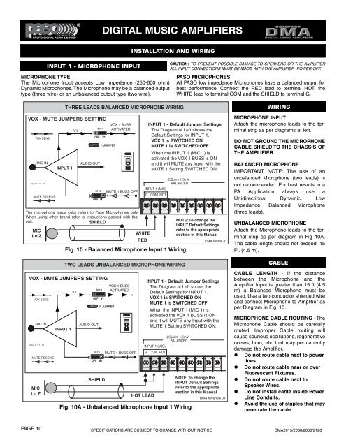
THREE LEADS BALANCED MICROPHONE WIRING<br />
VOX - MUTE JUMPERS SETTING<br />
The microphone leads color refers to Paso Microphones only.<br />
When using other brand refer to instructions packed with that<br />
unit.<br />
SHIELD<br />
MIC<br />
Lo Z<br />
VOX SEND<br />
MIC IN<br />
Input 1 - V1 - 01<br />
MUTE RECEIVE<br />
MIC<br />
Lo Z<br />
INPUT 1<br />
INPUT 1<br />
V1<br />
JUMPER = JUMPER<br />
AUDIO OUT<br />
S114<br />
OFF V1<br />
VOX 1 BUSS<br />
ACTIVATED<br />
JUMPER<br />
S113 MUTE 1 BUSS OFF<br />
X<br />
OFF M1<br />
WHITE<br />
RED<br />
INPUT 1 - Default Jumper Settings<br />
The Diagram at Left shows the<br />
Default Settings for INPUT 1.<br />
VOX 1 is SWITCHED ON<br />
MUTE 1 is SWITCHED OFF<br />
When the INPUT 1 (MIC 1) is<br />
activated the VOX 1 BUSS is ON<br />
and it will MUTE any Input with the<br />
MUTE 1 Setting SWITCHED ON.<br />
INPUT 1 (MIC)<br />
G COM HOT<br />
250ohm 1.5mV<br />
BALANCED<br />
Fig. 10 - Balanced Microphone Input 1 Wiring<br />
TWO LEADS UNBALANCED MICROPHONE WIRING<br />
VOX - MUTE JUMPERS SETTING<br />
V1<br />
JUMPER = JUMPER<br />
AUDIO OUT<br />
S114<br />
OFF V1<br />
SHIELD<br />
VOX 1 BUSS<br />
ACTIVATED<br />
JUMPER<br />
S113 MUTE 1 BUSS OFF<br />
X<br />
OFF M1<br />
HOT LEAD<br />
NOTE: To change the<br />
INPUT Default Settings<br />
refer to the appropriate<br />
section in this Manual<br />
DMA Micbal 01<br />
INPUT 1 - Default Jumper Settings<br />
The Diagram at Left shows the<br />
Default Settings for INPUT 1.<br />
VOX 1 is SWITCHED ON<br />
MUTE 1 is SWITCHED OFF<br />
When the INPUT 1 (MIC 1) is<br />
activated the VOX 1 BUSS is ON<br />
and it will MUTE any Input with the<br />
MUTE 1 Setting SWITCHED ON.<br />
250ohm 1.5mV<br />
BALANCED<br />
INPUT 1 (MIC)<br />
G COM HOT<br />
Fig. 10A - Unbalanced Microphone Input 1 Wiring<br />
NOTE: To change the<br />
INPUT Default Settings<br />
refer to the appropriate<br />
section in this Manual<br />
DMA Micunbal 01<br />
WIRING<br />
MICROPHONE INPUT<br />
Attach the microphone leads to the terminal<br />
strip as per diagrams at left.<br />
DO NOT GROUND THE MICROPHONE<br />
CABLE SHIELD TO THE CHASSIS OF<br />
THE AMPLIFIER<br />
BALANCED MICROPHONE<br />
IMPORTANT NOTE: The use of an<br />
unbalanced Microphone (two leads) is<br />
not recommended. For best results in a<br />
PA Application always use a<br />
Unidirectional Dynamic, Low<br />
Impedance, Balanced Microphone<br />
(three leads).<br />
UNBALANCED MICROPHONE<br />
Attach the Microphone leads to the terminal<br />
strip as per diagram in Fig 10A.<br />
The cable length should not exceed: 15<br />
Ft. (4.5 m).<br />
CABLE<br />
CABLE LENGTH - If the distance<br />
between the Microphone and the<br />
Amplifier Input is greater than 15 ft (4.5<br />
m) a Balanced Microphone must be<br />
used. Use a two conductor shielded wire<br />
and connect Microphone to Amplifier as<br />
per Diagram in Fig. 10.<br />
MICROPHONE CABLE ROUTING - The<br />
Microphone Cable should be carefully<br />
routed. Improper Cable routing will<br />
cause spurious oscillations, regenerative<br />
noises, hum, etc. that may permanently<br />
damage the Amplifier.<br />
• Do not route cable next to power<br />
lines.<br />
• Do not route cable near or over<br />
Fluorescent Fixtures.<br />
• Do not route cable next to<br />
Speaker Wires.<br />
• Do not install cable inside Power<br />
Line Conduits.<br />
• Avoid the use of staples that may<br />
penetrate the cable.<br />
PAGE 10<br />
SPECIFICATIONS ARE SUBJECT TO CHANGE WITHOUT NOTICE<br />
DMA2015/2030/2060/2120