

Amplifiers
digital music amplifiers - Paso Sound Products
digital music amplifiers - Paso Sound Products

Create successful ePaper yourself
Turn your PDF publications into a flip-book with our unique Google optimized e-Paper software.
PROFESSIONAL AUDIO & SOUND<br />
®<br />
DIGITAL MUSIC AMPLIFIERS<br />
INSTALLATION AND WIRING<br />
MOH CONNECTIONS<br />
Telephone<br />
MOH<br />
Input<br />
600<br />
Ohm<br />
600 ohm MOH System<br />
AWG 18 TWISTED PAIR<br />
3<br />
4<br />
Telephone System<br />
KSU<br />
1<br />
8<br />
8 OHM<br />
2 Watt Max.<br />
24 V DC<br />
250 MA<br />
- +<br />
DMA2015<br />
15W RMS<br />
MOH - ZONE 1<br />
INPUT SOURCE<br />
DEFAULT JUMPER<br />
SETTING<br />
S107<br />
VOX<br />
SENS<br />
MUTE<br />
DELAY<br />
3 - 60 SEC<br />
AUX1<br />
AUX2<br />
SP<br />
DMA2015 MOH Zone 1<br />
MOH OTPUT LEVEL CONTROL<br />
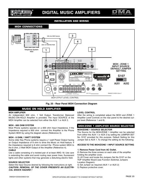
Fig. 25 - Rear Panel MOH Connection Diagram<br />
MUSIC ON HOLD AMPLIFIER<br />
MOH AMPLIFIER<br />
An independent 600 ohm, 1 Volt Output, Transformer Balanced<br />
MUSIC-ON-HOLD Amplifier is provided. The Input SOURCE of the<br />
MOH Amplifier can be selected from either the AUX 1 or AUX 2.<br />
MOH - 600 OHM SYSTEM<br />
Most Phone systems operate on a 600 ohm Input Impedance, if the<br />
Impedance required is 600 ohm connect the Amplifier to the Phone<br />
System MOH by using the diagram above (Reference 3).<br />
MOH - 8 OHM, 1 WATT SYSTEM<br />
Some older Key Phone systems require a 1 watt Power Output having<br />
an Output Impedance of 8 ohm to drive the Music on Hold feature. If<br />
the Impedance required is 8 ohm connect the Phone system MOH to<br />
the 8 ohm, 2 Watt MOH Output of the Amplifier (Reference 4).<br />
CABLE<br />
Use a cable consisting of a twisted pair of at least AWG 18. Use care<br />
in extending the cable and avoid routing near power lines, fluorescent<br />
lights and other systems that may generate a disturbing electric field.<br />
SOURCE SELECTOR<br />
Select the Input Source desired by following the instructions at right.<br />
CAUTION: REMOVAL OF THE COVER PRESENTS AN ELECTRI-<br />
CAL SHOCK HAZARD !<br />
LEVEL CONTROL<br />
After the wiring is completed adjust the MOH and ZONE 1<br />
Amplifier Level Controls on the rear panel to the desired output<br />
level (Reference 1 and 8).<br />
MOH/ZONE 1 AMPLIFIER SOURCE SELECTOR<br />
MOH/ZONE 1 SOURCE SELECTOR<br />
The Source for the MOH/ZONE 1 Amplifier can be selected<br />
from either the AUX 1 or AUX 2 by setting the JUMPER SET<br />
No. S107 provided for this purpose. Default Setting for this<br />
Jumper Set is AUX 1. To change the setting do the following:<br />
ACCESS TO THE MOH/ZONE 1 INPUT SOURCE SETTING<br />
1) Remove Power Cord from AC Outlet.<br />
2) Remove the three screws on each side of the amplifier<br />
holding the amplifier cover.<br />
3) Lift Cover and locate the Jumpers Set No S107 on the<br />
TOP Amplifier Board (see Function Switches Jumpers<br />
Location Diagram).<br />
4) Set Jumper as required (AUX 1 or AUX 2)<br />
5) Replace protective cover.<br />
DMA2015/2030/2060/2120<br />
SPECIFICATIONS ARE SUBJECT TO CHANGE WITHOUT NOTICE<br />
PAGE 25