

Amplifiers
digital music amplifiers - Paso Sound Products
digital music amplifiers - Paso Sound Products

You also want an ePaper? Increase the reach of your titles
YUMPU automatically turns print PDFs into web optimized ePapers that Google loves.
PROFESSIONAL AUDIO & SOUND<br />
®<br />
DIGITAL MUSIC AMPLIFIERS<br />
INSTALLATION AND WIRING<br />
OUTPUT CONNECTIONS<br />
CONSTANT VOLTAGE DISTRIBUTION SYSTEMS<br />
25 VOLT AND 70 VOLT CONSTANT VOLTAGE DISTRIBUTION SYSTEMS - In applications requiring a large number of speakers that<br />
are located at a far distance from the amplifier a 25 Volt or a 70 Volt Constant Voltage method is most widely used.<br />
MAIN ADVANTAGES IN USING THE HIGH IMPEDANCE METHOD<br />
1) All speakers are connected in parallel usually on to a single speaker line.<br />
2) The Amplifier Output Voltage is constant over a very wide range of load impedance.<br />
3) The Amplifier Output Voltage remains practically constant if loudspeakers are connected or disconnected from the line.<br />
4) Different acoustic power can be allocated in each area as required by using the power taps on the speaker line transformer.<br />
5) Since the system provides a higher voltage at a lower current, resistive loss in the cable is reduced resulting in a higher efficiency.<br />
6) Calculations of the output power needed and the speaker power requirements are simple and easily accomplished.<br />
spk 1<br />
spk 2<br />
0<br />
0.6<br />
spk 1 spk 2 spk 3 spk 4<br />
70 Volt<br />
Transformer<br />
COM 8 25V 70V<br />
1.25<br />
2.5<br />
5<br />
70 Volt<br />
Transformer<br />
0<br />
0.6<br />
1.25<br />
2.5<br />
5<br />
70 Volt<br />
Transformer<br />
0<br />
0.6<br />
1.25<br />
2.5<br />
5<br />
0<br />
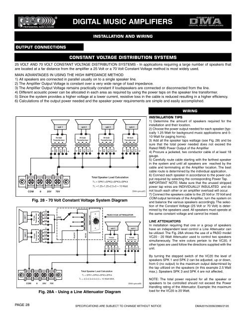
Total Speaker Load Calculation<br />
TL = SPK1+SPK2+SPK3+SPK4<br />
TL =1.25+1.25+2.5+5 = 10 Watt<br />
Fig. 28 - 70 Volt Constant Voltage System Diagram<br />
70 Volt<br />
Transformer<br />
70 Volt<br />
Transformer<br />
5<br />
2.5<br />
1.25<br />
0.6<br />
0<br />
5<br />
2.5<br />
1.25<br />
0.6<br />
0<br />
RED<br />
BLACK<br />
BLUE<br />
0<br />
0.6<br />
1.25<br />
2.5<br />
5<br />
70 Volt<br />
Transformer<br />
0<br />
0.6<br />
0.6<br />
1.25<br />
PASO VC20 ATTENUATOR<br />
spk 3 spk 4<br />
70 Volt<br />
Transformer<br />
2.5<br />
70 Volt<br />
Transformer<br />
5<br />
DMA spkout05<br />
1.25<br />
2.5<br />
5<br />
WIRING<br />
INSTALLATION TIPS<br />
1) Determine the amount of speakers required for the<br />
installation and their location.<br />
2) Choose the power output needed for each speaker (typically<br />
1.25 Watt for background music applications and 5-<br />
10 Watt for paging horns).<br />
3) Add all the speaker taps wattage (see Fig. 28) and be<br />
sure that the total power needed does not exceed the<br />
Rated RMS Power Output of the Amplifier<br />
4) Procure a jacketed, two conductor cable of at least 18<br />
gauge.<br />
5) Carefully route cable starting with the farthest speaker<br />
in the system and until all speakers are reached by the<br />
cable and terminating at the Amplifier location. The best<br />
cable route is determined by the individual application.<br />
6) Connect each speaker in accordance to the power output<br />
required by selecting the corresponding Power Tap.<br />
IMPORTANT NOTE: Make sure that the unused stripped<br />
power tap wires are INDIVIDUALLY INSULATED and do<br />
not touch each other or an amplifier overload will occur.<br />
7) Connect the speakers cable to the 25 Volt or 70 Volt and<br />
COM output terminals of the Amplifier, turn the system on<br />
and balance the various speakers accordingly. The selection<br />
of the Constant Voltage (25 Volt or 70 Volt) is determined<br />
by the speakers used. All speakers must operate at<br />
the same constant voltage and cannot be mixed.<br />
LINE ATTENUATORS<br />
In installation requiring that one or a group of speakers<br />
have an independent level control a Line Attenuator can<br />
be utilized. The Fig. 28A shows the use of a PASO model<br />
VC20 - 20 Watt Attenuator used to control two speakers<br />
simultaneously. The wire colors pertain to the VC20, if<br />
other types are used follow the directions supplied with the<br />
unit.<br />
Total Speaker Load Calculation<br />
TL = SPK1+SPK2+SPK3+SPK4<br />
TL = 2.5+2.5+2.5+2.5 = 10 Watt MAX.<br />
COM 8 25V 70V<br />
Fig. 28A - Using a Line Attenuator Diagram<br />
DMA spkout06<br />
By turning the stepped switch of the VC20 the level of<br />
speakers SPK 1 and SPK 2 can be adjusted, up or down,<br />
from 0 (no output) to the maximum output determined by<br />
the tap utilized on the speakers (in this example 2.5 Watt<br />
max.). Speakers SPK 3 and SPK 4 are not affected.<br />
NOTE: The total power required for all the speaker or<br />
speakers to be controlled should not exceed the Power<br />
Handling rating of the Attenuator. Example: the maximum<br />
load for the VC20 is 20 Watt.<br />
PAGE 28<br />
SPECIFICATIONS ARE SUBJECT TO CHANGE WITHOUT NOTICE<br />
DMA2015/2030/2060/2120