

Amplifiers
digital music amplifiers - Paso Sound Products
digital music amplifiers - Paso Sound Products

Create successful ePaper yourself
Turn your PDF publications into a flip-book with our unique Google optimized e-Paper software.
PROFESSIONAL AUDIO & SOUND<br />
®<br />
DIGITAL MUSIC AMPLIFIERS<br />
INSTALLATION AND WIRING<br />
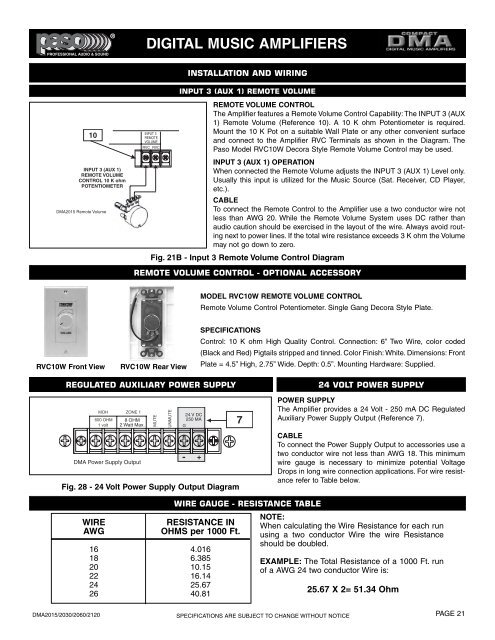
INPUT 3 (AUX 1) REMOTE VOLUME<br />
10<br />
INPUT 3 (AUX 1)<br />
REMOTE VOLUME<br />
CONTROL 10 K ohm<br />
POTENTIOMETER<br />
DMA2015 Remote Volume<br />
INPUT 3<br />
REMOTE<br />
VOLUME<br />
RVC RVC<br />
REMOTE VOLUME CONTROL<br />
The Amplifier features a Remote Volume Control Capability: The INPUT 3 (AUX<br />
1) Remote Volume (Reference 10). A 10 K ohm Potentiometer is required.<br />
Mount the 10 K Pot on a suitable Wall Plate or any other convenient surface<br />
and connect to the Amplifier RVC Terminals as shown in the Diagram. The<br />
Paso Model RVC10W Decora Style Remote Volume Control may be used.<br />
INPUT 3 (AUX 1) OPERATION<br />
When connected the Remote Volume adjusts the INPUT 3 (AUX 1) Level only.<br />
Usually this input is utilized for the Music Source (Sat. Receiver, CD Player,<br />
etc.).<br />
CABLE<br />
To connect the Remote Control to the Amplifier use a two conductor wire not<br />
less than AWG 20. While the Remote Volume System uses DC rather than<br />
audio caution should be exercised in the layout of the wire. Always avoid routing<br />
next to power lines. If the total wire resistance exceeds 3 K ohm the Volume<br />
may not go down to zero.<br />
Fig. 21B - Input 3 Remote Volume Control Diagram<br />
REMOTE VOLUME CONTROL - OPTIONAL ACCESSORY<br />
MODEL RVC10W REMOTE VOLUME CONTROL<br />
Remote Volume Control Potentiometer. Single Gang Decora Style Plate.<br />
RVC10W Front View<br />
RVC10W Rear View<br />
SPECIFICATIONS<br />
Control: 10 K ohm High Quality Control. Connection: 6” Two Wire, color coded<br />
(Black and Red) Pigtails stripped and tinned. Color Finish: White. Dimensions: Front<br />
Plate = 4.5” High, 2.75” Wide. Depth: 0.5”. Mounting Hardware: Supplied.<br />
REGULATED AUXILIARY POWER SUPPLY<br />
8 OHM<br />
2 Watt Max.<br />
DMA Power Supply Output<br />
24 V DC<br />
250 MA<br />
- +<br />
Fig. 28 - 24 Volt Power Supply Output Diagram<br />
7<br />
24 VOLT POWER SUPPLY<br />
POWER SUPPLY<br />
The Amplifier provides a 24 Volt - 250 mA DC Regulated<br />
Auxiliary Power Supply Output (Reference 7).<br />
CABLE<br />
To connect the Power Supply Output to accessories use a<br />
two conductor wire not less than AWG 18. This minimum<br />
wire gauge is necessary to minimize potential Voltage<br />
Drops in long wire connection applications. For wire resistance<br />
refer to Table below.<br />
WIRE<br />
AWG<br />
WIRE GAUGE - RESISTANCE TABLE<br />
RESISTANCE IN<br />
OHMS per 1000 Ft.<br />
16 4.016<br />
18 6.385<br />
20 10.15<br />
22 16.14<br />
24 25.67<br />
26 40.81<br />
NOTE:<br />
When calculating the Wire Resistance for each run<br />
using a two conductor Wire the wire Resistance<br />
should be doubled.<br />
EXAMPLE: The Total Resistance of a 1000 Ft. run<br />
of a AWG 24 two conductor Wire is:<br />
25.67 X 2= 51.34 Ohm<br />
DMA2015/2030/2060/2120<br />
SPECIFICATIONS ARE SUBJECT TO CHANGE WITHOUT NOTICE<br />
PAGE 21