

Amplifiers
digital music amplifiers - Paso Sound Products
digital music amplifiers - Paso Sound Products

You also want an ePaper? Increase the reach of your titles
YUMPU automatically turns print PDFs into web optimized ePapers that Google loves.
PROFESSIONAL AUDIO & SOUND<br />
®<br />
DIGITAL MUSIC AMPLIFIERS<br />
CAUTION ! REMOVAL OF THE AMPLIFIER COVER PRESENTS AN ELECTRICAL SHOCK HAZARD<br />
ALWAYS REMOVE THE POWER CORD FROM THE AC WALL OUTLET<br />
THE FOLLOWING INSTRUCTIONS REQUIRE THE REMOVAL OF THE AMPLIFIER PROTECTIVE COVER AND ARE<br />
PROVIDED FOR USE BY QUALIFIED PERSONNEL ONLY.<br />
TO AVOID THE RISK OF ELECTRICAL SHOCK DO NOT PERFORM ANY INSTALLATION OR SERVICING UNLESS YOU<br />
ARE QUALIFIED TO DO SO. REFER INSTALLATION OR SERVICING TO QUALIFIED PERSONNEL.<br />
INPUT CONNECTIONS<br />
CONDENSER AND ELECTRET MICROPHONES<br />
CONDENSER AND ELECTRET TYPE MICROPHONES<br />
Condenser and Electret Microphones require a DC Operating<br />
Voltage. The Amplifier provides this operating voltage or Phantom<br />
Power selectively on Inputs.1-3-4.<br />
Prior to selecting the Condenser or Electret Microphone be sure<br />
that the Operating Voltage and Output Impedance of the device<br />
match the Input characteristics of the Amplifier listed below.<br />
Phantom Power<br />
Input Impedance<br />
= 18 Volt DC<br />
= 250 to 600 ohm<br />
ACCESS TO PHANTOM POWER SELECTORS<br />
1) Remove Power Cord from AC Outlet.<br />
2) Remove the three screws on each side of the Amplifier.<br />
3) Lift Cover and carefully slide Cover out towards the rear.<br />
4) Jumpers are located on the Top Printed Circuit Board.<br />
CONFIGURATION TABLES<br />
PHANTOM POWER SELECTORS<br />
PHANTOM POWER SELECTOR JUMPER<br />
By following the Main Printed Board Layout locate the Selector<br />
Jumpers with the ID No. as indicated on the Table below.<br />
Reset the Phantom Power Jumpers for INPUT 1 - 3 or 4 to the ON<br />
position as desired. Lift the Mini Jumper out of the socket pins and<br />
re-position to the ON position. Make sure the Jumper is lined up<br />
with the socket pins.<br />
INPUT 4 and 5 CONFIGURED AS MIC INPUTS<br />
If INPUT 4 and INPUT5 need to be configured as Microphone<br />
Inputs, reset the Phantom Power Jumpers as well as the<br />
Switches provided for the two Inputs as indicated in the Table<br />
below.<br />
WIRING<br />
CONDENSER/ELECTRET MICROPHONE<br />
Carefully follow the wiring instruction packed with the Microphone<br />
used. Attach the microphone leads to the terminal strip as per diagram<br />
per Fig. below.<br />
DO NOT GROUND THE MICROPHONE CABLE SHIELD TO THE<br />
CHASSIS OF THE AMPLIFIER<br />
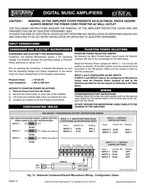
BALANCED CONDENSER/ELECTRET MICROPHONE WIRING<br />
MIC INPUTS PHANTOM POWER JUMPER SETTING<br />
WHEN USING ELECTRET MICROPHONES<br />
INPUT 1 On JUMPER OFF<br />
S104<br />
INPUT 3 On JUMPER OFF (When set as MIC 3)<br />
S103<br />
INPUT 4 On JUMPER OFF (When set as MIC 4)<br />
S102<br />
MIC<br />
Lo Z<br />
INPUT 3 - 4 SWITCH SETTINGS WHEN<br />
CONFIGURING AS MICROPHONE INPUT<br />
Input Switch No. Setting<br />
INPUT 3 S109 MIC 3<br />
INPUT 4 S101 MIC 4<br />
INPUT 3 (MIC)<br />
G COM HOT<br />
SHIELD<br />
TEL (PAGING)<br />
G COM HOT<br />
INPUT 1 (MIC)<br />
G COM HOT<br />
HOT LEAD<br />
HOT LEAD<br />
-0 +18V +18V<br />
Input<br />
INPUT 3 - 4 DEFAULT<br />
SWITCH SETTINGS<br />
Switch No. Setting<br />
INPUT 3 S109 AUX 1<br />
INPUT 4 S101 AUX 2<br />
INPUT 1- 3 - 4 DEFAULT<br />
JUMPER SETTINGS<br />
Input Jumper No. Setting<br />
INPUT 1 S104 OFF<br />
INPUT 3 S103 OFF<br />
INPUT 4 S102 OFF<br />
DMA2015 Micbal Electret<br />
Fig. 12 - Balanced Condenser/Electret Microphone Wiring - Configuration Tables<br />
PAGE 12<br />
SPECIFICATIONS ARE SUBJECT TO CHANGE WITHOUT NOTICE<br />
DMA2015/2030/2060/2120