

Amplifiers
digital music amplifiers - Paso Sound Products
digital music amplifiers - Paso Sound Products

You also want an ePaper? Increase the reach of your titles
YUMPU automatically turns print PDFs into web optimized ePapers that Google loves.
PROFESSIONAL AUDIO & SOUND<br />
®<br />
DIGITAL MUSIC AMPLIFIERS<br />
CAUTION !<br />
INSTALLATION AND WIRING<br />
REMOVAL OF THE AMPLIFIER COVER PRESENTS AN ELECTRICAL SHOCK HAZARD<br />
ALWAYS REMOVE THE POWER CORD FROM THE AC WALL OUTLET<br />
THE FOLLOWING INSTRUCTIONS REQUIRE THE REMOVAL OF THE AMPLIFIER PROTECTIVE COVER AND ARE PROVIDED<br />
FOR USE BY QUALIFIED PERSONNEL ONLY. TO AVOID THE RISK OF ELECTRICAL SHOCK DO NOT PERFORM ANY INSTALLA-<br />
TION OR SERVICING UNLESS YOU ARE QUALIFIED TO DO SO.<br />
INPUT 1 (MIC 1) UNMUTING FUNCTION<br />
DIRECT UNMUTING<br />
INPUT 1 (MIC 1) UNMUTING FUNCTION<br />
The Input 1 (MIC 1) can be preset to be normally MUTED (INPUT<br />
OFF) when the JUMPER S115 - MIC 1 UNMUTE - IS SET TO THE<br />
ON POSITION. The MIC 1 is SWITCHED-ON when the UNMUTE<br />
and G Terminals are shorted by a Switch Contact Closure. This<br />
function allows for a multi zone installation using two or more<br />
<strong>Amplifiers</strong> and a single Microphone and Zone Switches. When the<br />
Jumper S115 is set to the ON Position the Microphone Input is<br />
OFF and it is turned ON when the UNMUTE and the G terminals<br />
are closed by a switch.<br />
JUMPER NO. FUNCTION POSITION SET<br />
S115 MIC 1 Muted ON<br />
If the Jumper requires resetting follow the instruction below.<br />
ACCESS TO UNMUTING JUMPER<br />
1) Remove Power Cord from AC Outlet.<br />
2) Remove the three screws on each side of the Amplifier<br />
securing the Top Cover to the Chassis.<br />
3) Lift Cover and carefully and slide Cover out towards the rear.<br />
4) On the Main Amplifier Printed Board locate the S115 -<br />
MIC 1 UNMUTE Jumper Set.<br />
5) Set Jumper to the ON position.<br />
ZONE UNMUTING SWITCH<br />
MIC<br />
Lo Z<br />
WIRING<br />
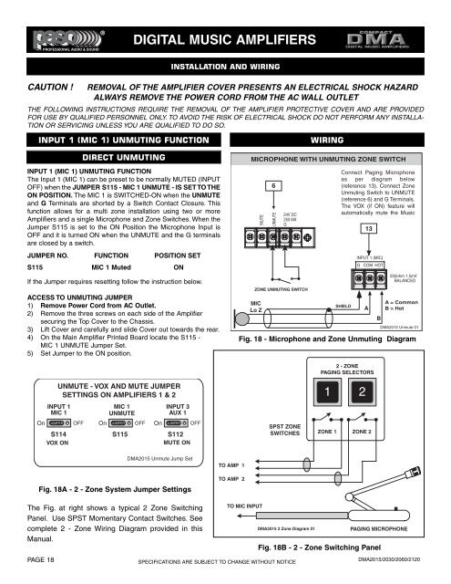
MICROPHONE WITH UNMUTING ZONE SWITCH<br />
MUTE<br />
6<br />
UNMUTE<br />
24V DC<br />
250 MA<br />
G<br />
Connect Paging Microphone<br />
as per diagram below<br />
(reference 13). Connect Zone<br />
Unmuting Switch to UNMUTE<br />
(reference 6) and G Terminals.<br />
The VOX (if ON) feature will<br />
automatically mute the Music<br />
SHIELD<br />
INPUT 1 (MIC)<br />
G COM HOT<br />
250ohm 1.5mV<br />
BALANCED<br />
DMA2015 Unmute 01<br />
Fig. 18 - Microphone and Zone Unmuting Diagram<br />
13<br />
A<br />
B<br />
A = Common<br />
B = Hot<br />
2 - ZONE<br />
PAGING SELECTORS<br />
UNMUTE - VOX AND MUTE JUMPER<br />
SETTINGS ON AMPLIFIERS 1 & 2<br />
1<br />
2<br />
INPUT 1<br />
MIC 1<br />
On JUMPER<br />
S114<br />
VOX ON<br />
OFF<br />
MIC 1<br />
UNMUTE<br />
On JUMPER OFF<br />
S115<br />
On<br />
INPUT 3<br />
AUX 1<br />
JUMPER<br />
S112<br />
MUTE ON<br />
OFF<br />
SPST ZONE<br />
SWITCHES<br />
ZONE 1<br />
ZONE 2<br />
DMA2015 Unmute Jump Set<br />
Fig. 18A - 2 - Zone System Jumper Settings<br />
TO AMP 1<br />
TO AMP 2<br />
The Fig. at right shows a typical 2 Zone Switching<br />
Panel. Use SPST Momentary Contact Switches. See<br />
complete 2 - Zone Wiring Diagram provided in this<br />
Manual.<br />
PAGE 18<br />
TO MIC INPUT<br />
DMA2015 2 Zone Diagram 01<br />
SPECIFICATIONS ARE SUBJECT TO CHANGE WITHOUT NOTICE<br />
PAGING MICROPHONE<br />
Fig. 18B - 2 - Zone Switching Panel<br />
DMA2015/2030/2060/2120