Conveying with ease Fitting and operational manual Declaration of ...
Conveying with ease Fitting and operational manual Declaration of ...
Conveying with ease Fitting and operational manual Declaration of ...

You also want an ePaper? Increase the reach of your titles
YUMPU automatically turns print PDFs into web optimized ePapers that Google loves.
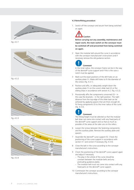
Fig. 4.3.1<br />
Fig. 4.3.2<br />
Fig. 4.3.3<br />
Fig. 4.3.4<br />
➌<br />
➋<br />
➊<br />
➍<br />
7 bmaKA_V1_E_2009.09_1000<br />
➎<br />
➊<br />
4.3 Retr<strong>of</strong>i tting procedure<br />
1. Switch <strong>of</strong>f the conveyor <strong>and</strong> secure from being switched<br />
on again.<br />
Caution<br />
Before carrying out any assembly, maintenance <strong>and</strong><br />
repair work, the main switch on the conveyor must<br />
be switched <strong>of</strong>f <strong>and</strong> prevented from being switched<br />
on again.<br />
2 Open the modular belt around the curve in accordance<br />
<strong>with</strong> the conveyor manufacturer’s instructions <strong>and</strong> if<br />
necessary remove the old guidance section.<br />
Comment<br />
In the inner radius, the conveyor frame can be in the way<br />
<strong>of</strong> the deniroll ® curve support <strong>and</strong> if this is the case a<br />
notch must be applied.<br />
3 Mark out the exact positions <strong>of</strong> the drill holes on an<br />
auxiliary plate (1). Make drill holes to fi t the diameter <strong>of</strong><br />
the screws (fi g. 4.3.1).<br />
4 Position <strong>and</strong> affi x, or adequately weight down the<br />
auxiliary plate (1) on the curve’s slider bed (2) or the<br />
sliding strips in accordance <strong>with</strong> section 4.2. (fi g. 4.3.2).<br />
5 Provisionally affi x the components concerned (3) – in<br />
this case the brackets – in the right position. The right<br />
distance from the top edge <strong>of</strong> the slider bed can be<br />
achieved by applying spacers that are thick enough (4).<br />
Fit fi xing components (3) to the inner radius <strong>of</strong> the curve<br />
(fi g. 4.3.3).<br />
Comment<br />
The fi tting height must be selected so that the modular<br />
belt does not come into contact <strong>with</strong> any fi xed parts <strong>of</strong><br />
the deniroll ® curve support <strong>and</strong> so that as much as<br />
possible <strong>of</strong> the areas at the side runs on the rollers.<br />
6 Loosen the screws between the fastening components<br />
<strong>and</strong> the auxiliary plate. Remove the auxiliary plate <strong>and</strong><br />
spacers.<br />
7 Assemble the deniroll ® curve support (5). Check the<br />
positioning <strong>of</strong> the curve support in accordance <strong>with</strong><br />
section 4.1 <strong>and</strong> correct if necessary (fi g. 4.3.4).<br />
8 Close the belt in the curve according to the conveyor<br />
manufacturer’s instructions.<br />
9 Check the positioning <strong>of</strong> the deniroll ® curve support again<br />
<strong>and</strong> adjust if necessary.<br />
– The play in the whole <strong>of</strong> the curve should be<br />
constant between the modular belts <strong>and</strong> any<br />
protruding guidance plates.<br />
– The modular belt must not come into contact <strong>with</strong> any<br />
fi xed parts on the deniroll ® curve support.<br />
10 Commission the conveyor according to the conveyor<br />
manufacturer’s instructions.