Research Journal of Science & IT Management - RJSITM - The ...
Research Journal of Science & IT Management - RJSITM - The ...
Research Journal of Science & IT Management - RJSITM - The ...

Create successful ePaper yourself
Turn your PDF publications into a flip-book with our unique Google optimized e-Paper software.
negative DC bus ,this current would commutate into the<br />
diode across the upper IGBT <strong>of</strong> the left leg ,if the lower<br />
IGBT is turned <strong>of</strong>f .Control <strong>of</strong> circuit is accomplished by<br />
varying the turn on time <strong>of</strong> the upper and lower IGBT <strong>of</strong><br />
each inverter leg ,with the provision <strong>of</strong> never turning on<br />
both at the same time ,to avoid a short circuit <strong>of</strong> the DC bus<br />
.In fact the modern drives does not allow this to happen<br />
even if the controller would erroneously command both<br />
controller devices to be turned on .<strong>The</strong> controller will<br />
therefore alternate the turn<br />
on command for the upper and lower switch .ie turn the<br />
upper switch on and the lower switch <strong>of</strong>f and vice versa<br />
.<strong>The</strong> drive circuit should add some additional blanking time<br />
(typically 500-1000ns) during the switch transitions to avoid<br />
any over lap in the condition intervals.<br />
<strong>The</strong> controller will control the duty cycle <strong>of</strong><br />
the conduction phase <strong>of</strong> the switches .<strong>The</strong> average potential<br />
<strong>of</strong> the centre point <strong>of</strong> each leg will be given by the DC bus<br />
voltage multiplied by the duty cycle <strong>of</strong> the upper switches ,if<br />
the negative side <strong>of</strong> the DC bus is used as a reference. If<br />
this duty cycle is modulated with a sinusoidal signal with a<br />
frequency much smaller than the switching frequency the<br />
short term average <strong>of</strong> the centre point potential will follow<br />
the modulation signal<br />
For a single phase inverter<br />
the modulation <strong>of</strong> the two legs are inverse <strong>of</strong> each other<br />
such that if the left leg has a large duty cycle for the upper<br />
switch , the right leg has a small one .<strong>The</strong> frequency ,wave<br />
shape and the amplitude <strong>of</strong> the inverter out put voltage can<br />
be controlled as long as the switching frequency is at least<br />
25 to 100 times higher than the fundamental output<br />
frequency <strong>of</strong> the inverter .<strong>The</strong> actual generation <strong>of</strong> PWM<br />
signals is done using microcontroller Fig 8 shows the<br />
control block diagram <strong>of</strong> photovoltaic power system .<br />
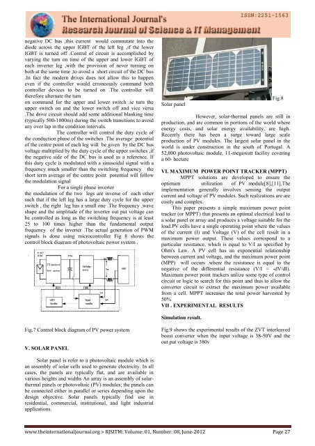
Solar panel<br />
Fig.8<br />
However, solar-thermal panels are still in<br />
production, and are common in portions <strong>of</strong> the world where<br />
energy costs, and solar energy availability, are high.<br />
Recently there has been a surge toward large scale<br />
production <strong>of</strong> PV modules. <strong>The</strong> largest solar panel in the<br />
world is under construction in the south <strong>of</strong> Portugal. A<br />
52,000 photovoltaic module, 11-megawatt facility covering<br />
a 60- hectare<br />
VI. MAXIMUM POWER POINT TRACKER (MPPT)<br />
MPPT solutions are developed to ensure the<br />
optimum utilization <strong>of</strong> PV module[8],[11].<strong>The</strong><br />
implementation generally involves sensing the output<br />
current and voltage <strong>of</strong> PV modules. Such realizations are are<br />
costly and complex.<br />
This paper presents a simple maximum power point<br />
tracker (or MPPT) that presents an optimal electrical load to<br />
a solar panel or array and produces a voltage suitable for the<br />
load.PV cells have a single operating point where the values<br />
<strong>of</strong> the current (I) and Voltage (V) <strong>of</strong> the cell result in a<br />
maximum power output. <strong>The</strong>se values correspond to a<br />
particular resistance, which is equal to V/I as specified by<br />
Ohm's Law. A PV cell has an exponential relationship<br />
between current and voltage, and the maximum power point<br />
(MPP) will occurs .where the resistance is equal to the<br />
negative <strong>of</strong> the differential resistance (V/I = -dV/dI).<br />
Maximum power point trackers utilize some type <strong>of</strong> control<br />
circuit or logic to search for this point and thus to allow the<br />
converter circuit to extract the maximum power available<br />
from a cell. MPPT increases the total power harvested by<br />
50%<br />
VII . EXPERIMENTAL RESULTS<br />
Simulation result.<br />
Fig.7 Control block diagram <strong>of</strong> PV power system<br />
V. SOLAR PANEL<br />
Fig.9 shows the experimental results <strong>of</strong> the ZVT interleaved<br />
boost converter when the input voltage is 38-50V and the<br />
out put voltage is 380v<br />
Solar panel is refer to a photovoltaic module which is<br />
an assembly <strong>of</strong> solar cells used to generate electricity. In all<br />
cases, the panels are typically flat, and are available in<br />
various heights and widths An array is an assembly <strong>of</strong> solarthermal<br />
panels or photovoltaic (PV) modules; the panels can<br />
be connected either in parallel or series depending upon the<br />
design objective. Solar panels typically find use in<br />
residential, commercial, institutional, and light industrial<br />
applications.<br />
www.theinternationaljournal.org > RJS<strong>IT</strong>M: Volume: 01, Number: 08, June-2012 Page 27