Gesamtkatalog 2016-2

Create successful ePaper yourself
Turn your PDF publications into a flip-book with our unique Google optimized e-Paper software.
Application Notes<br />
2mm HPM PSeries<br />
age 13<br />
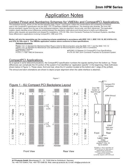
Contact Pinout and Numbering Schemes for VME64x and CompactPCI Applications.<br />
The backplane layouts, shown on this and the following page, Figure 1 and Figure 2 depict the nomenclature and numbering conventions<br />
used in the CompactPCI specification and the IEEE 1101.10 Standard (VME64x applications). The drawings also illustrate the 2mm HM<br />
shroud orientation viewed from the rear of the backplane/midplane. Note the alignment, shroud side, and latch referenced. This application<br />
notation clearly identifies pinout differences existing between the standards noted above and should serve to clarify such differences<br />
before cable requests are assembled and shipped for installations. VITA 30-199x, 2mm Connector Practices for Euroboard Systems, identifies<br />
these differences in applications involving CompactPCI, VME and VITA.<br />
Meritec will wire the assemblies per the numbering scheme established in accordance with IEEE 1101.1, IEEE 1101.10, IEC 61076-4-101,<br />
and VITA 30-199x style V. The VME64x application notation above conforms to these specifications.<br />
Reference documents:<br />
IEEE 1101.11 Standard for Mechanical Rear Plug-in Units for Microcomputers using the IEEE 1101.1 and the IEEE 1101.10<br />
IEEE 1101.10 Standard for Mechanical Core Specification for Microcomputers using IEC 603-2 Connectors<br />
Equipment Practices<br />
IEC 61076-4-101<br />
PICMG 2.0 Release 3.0 CompactPCI Core Specifications<br />
VITA 1.1-1997 VME 64 Extensions<br />
VITA 30-1997 2mm Connector Practices for Euroboard System<br />
CompactPCI Applications.<br />
As is typical in some telecommunications, the CompactPCI specification numbers the signals starting from the bottom up. These<br />
differences can complicate the I/O portion of the system if not identified as “application specific” in the beginning.( Note bothviews<br />
shown below in Figure 1). These views, front and rear, show the A1 position located at the bottom-slot 1 edge of the pinfield.<br />
The shroud and latch orientations are shown to depict proper alignment when the cable interface is attached.<br />
Figure 1<br />
Figure 1-6UCompact PCI Backplane Layout<br />
Male Male Male<br />
15<br />
11<br />
1<br />
19<br />
1<br />
22<br />
2.675<br />
2.675<br />
15<br />
11<br />
1<br />
19<br />
1<br />
22<br />
Male Male Male<br />
2mm HM<br />
header w/<br />
feed through<br />
pins<br />
P3<br />
Front<br />
Compact PCI<br />
backplane<br />
ERNI Shroud<br />
ERNI<br />
latch arm<br />
064219<br />
Rear<br />
Front View<br />
1<br />
ZABCDEF<br />
1<br />
FEDCBAZ<br />
Rear View<br />
Latch View<br />
(Side)<br />
Facing Row F<br />
position 1 thru 19<br />
top to bottom<br />
PICMG 2.1 R3.0 specifies an<br />
AB19 shroud for rear plug in<br />
applications (rP3/rJ3).<br />
However, cable assemblies<br />
used for I/O routing<br />
currently require a B19 shroud.<br />
A P Products GmbH, Bäumlesweg 21 – 23, 71093 Weil im Schönbuch, Germany<br />
Tel: +49-7157-5348-0, Fax: +49-7157-5348-39, Web: www.ap-products.de, E-mail: info@ap-products.de