Anritsu Site Master S332B User Guide - Mr Test Equipment
Anritsu Site Master S332B User Guide - Mr Test Equipment
Anritsu Site Master S332B User Guide - Mr Test Equipment

Create successful ePaper yourself
Turn your PDF publications into a flip-book with our unique Google optimized e-Paper software.
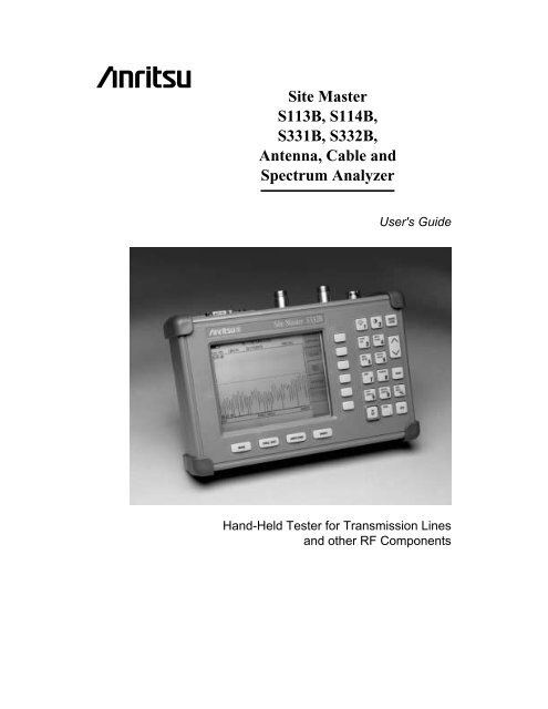
<strong>Site</strong> <strong>Master</strong><br />
S113B, S114B,<br />
S331B, <strong>S332B</strong>,<br />
Antenna, Cable and<br />
Spectrum Analyzer<br />
<strong>User</strong>'s <strong>Guide</strong><br />
Hand-Held <strong>Test</strong>er for Transmission Lines<br />
and other RF Components
WARRANTY<br />
The <strong>Anritsu</strong> product(s) listed on the title page is (are) warranted against defects in<br />
materials and workmanship for one year from the date of shipment.<br />
<strong>Anritsu</strong>'s obligation covers repairing or replacing products which prove to be defective<br />
during the warranty period. Buyers shall prepay transportation charges for<br />
equipment returned to <strong>Anritsu</strong> for warranty repairs. Obligation is limited to the original<br />
purchaser. <strong>Anritsu</strong> is not liable for consequential damages.<br />
LIMITATION OF WARRANTY<br />
The foregoing warranty does not apply to <strong>Anritsu</strong> connectors that have failed due to<br />
normal wear. Also, the warranty does not apply to defects resulting from improper or<br />
inadequate maintenance by the Buyer, unauthorized modification or misuse, or operation<br />
outside the environmental specifications of the product. No other warranty is<br />
expressed or implied, and the remedies provided herein are the Buyer's sole and<br />
exclusive remedies.<br />
TRADEMARK ACKNOWLEDGMENTS<br />
MS-DOS, Windows, Windows 95, Windows NT, and Windows 98 are registered<br />
trademarks of the Microsoft Corporation.<br />
<strong>Anritsu</strong> and <strong>Site</strong> <strong>Master</strong> are trademarks of <strong>Anritsu</strong> Company.<br />
NOTICE<br />
<strong>Anritsu</strong> Company has prepared this manual for use by <strong>Anritsu</strong> Company personnel<br />
and customers as a guide for the proper installation, operation and maintenance of<br />
<strong>Anritsu</strong> Company equipment and computer programs. The drawings, specifications,<br />
and information contained herein are the property of <strong>Anritsu</strong> Company, and any unauthorized<br />
use or disclosure of these drawings, specifications, and information is<br />
prohibited; they shall not be reproduced, copied, or used in whole or in part as the<br />
basis for manufacture or sale of the equipment or software programs without the<br />
prior written consent of <strong>Anritsu</strong> Company.<br />
June 2002 10580-00028<br />
Copyright � 1999-2002 <strong>Anritsu</strong> Co. Revision: F
Table of Contents<br />
Chapter 1 - General Information 1-1<br />
Introduction. .................................1-1<br />
Description ..................................1-1<br />
Standard Accessories .............................1-1<br />
Options ....................................1-2<br />
Optional Accessories .............................1-2<br />
Performance Specifications .........................1-3<br />
Preventive Maintenance ...........................1-6<br />
ESD Precautions ...............................1-6<br />
Calibration ..................................1-7<br />
Annual Verification. .............................1-7<br />
Chapter 2 - Getting Started 2-1<br />
Introduction. .................................2-1<br />
Charging a New Battery ...........................2-1<br />
Charging the Battery in the <strong>Site</strong> <strong>Master</strong> .....................2-1<br />
Charging the Battery in the Optional Charger ..................2-1<br />
Determining Remaining Battery Life ....................2-2<br />
Battery Life ..................................2-3<br />
Important Battery Information ..........................2-4<br />
Chapter 3 - Functions and Operations 3-1<br />
Introduction. .................................3-1<br />
Front Panel Overview ............................3-1<br />
<strong>Test</strong> Connector Panel. ............................3-2<br />
Keypad Controls ...............................3-3<br />
Soft Keys ...................................3-6<br />
Power Monitor Menu ............................3-18<br />
Printing. ...................................3-19<br />
Printing a Screen .................................3-19<br />
Printer Switch Settings ..............................3-20<br />
Symbols ...................................3-21<br />
Self <strong>Test</strong> ...................................3-21<br />
Error Codes .................................3-22<br />
Self <strong>Test</strong> Errors ..................................3-22<br />
Range Errors ...................................3-23<br />
Using the Soft Carrying Case. .......................3-25<br />
i
ii<br />
Chapter 4 - Measurements 4-1<br />
Introduction. .................................4-1<br />
Measurement Functions ...........................4-1<br />
Power On Procedure .............................4-2<br />
Calibration Procedure ............................4-2<br />
Selecting the Frequency Range ..........................4-3<br />
Performing a Calibration .............................4-3<br />
Saving the Setup ..................................4-4<br />
Recalling a Setup ..................................4-4<br />
Saving a Display to Memory ............................4-4<br />
Recalling a Display From Memory ........................4-4<br />
SWR (Return Loss) and Cable Loss Measurement ............4-6<br />
Required <strong>Equipment</strong> ................................4-6<br />
Device-Under-<strong>Test</strong> Specification. .........................4-6<br />
Procedure ......................................4-6<br />
Selecting the Measurement Mode .........................4-6<br />
Selecting the Frequency Range ..........................4-6<br />
Performing a Calibration .............................4-7<br />
SWR or Return Loss Measurement ........................4-8<br />
Set the Amplitude Scale and Limit Line .....................4-8<br />
Setting the Markers. ................................4-9<br />
Cable Loss Measurement ..........................4-10<br />
Setting the Amplitude Scale ...........................4-10<br />
Setting the Markers ................................4-10<br />
DTF Measurement .............................4-12<br />
Required <strong>Equipment</strong> ...............................4-12<br />
Device-Under-<strong>Test</strong> Specification .........................4-12<br />
Procedure .....................................4-12<br />
Selecting the Measurement Mode ........................4-12<br />
Performing a Calibration .............................4-13<br />
DTF Measurement (Determining the Length of the Cable) ..........4-14<br />
Setting the Amplitude Scale ...........................4-14<br />
Setting the Marker ................................4-14<br />
DTF Measurement (Determining the quality of the cable.) ..........4-16<br />
Setting the Amplitude Scale ...........................4-16<br />
Setting the Markers ................................4-16<br />
Making Power Measurements .......................4-18<br />
Entering Power Monitor Mode. .........................4-18<br />
Zeroing the Power Monitor. ...........................4-18<br />
Measuring High Input Power Levels. ......................4-18<br />
Displaying Power in dBm and Watts ......................4-18<br />
Displaying Relative Power ............................4-18<br />
Making a Measurement with the Spectrum Analyzer ..........4-19<br />
Example – Measuring a 900 MHz signal. .................4-19<br />
Set the <strong>Site</strong> <strong>Master</strong> to Spectrum Analyzer mode ................4-19<br />
Set the center frequency .............................4-19<br />
Set the frequency span ..............................4-20<br />
Setting the marker. ................................4-20<br />
Set the Reference Level ..............................4-21
Chapter 5 - Software Tools<br />
Program 5-1<br />
Description ..................................5-1<br />
Requirements .................................5-1<br />
Communication Port Setting. ........................5-1<br />
Changing COM Port Settings–Windows 95/98/NT ...............5-1<br />
Software Installation .............................5-3<br />
Plot Capture. .................................5-3<br />
Capture multiple traces to a database. ......................5-4<br />
Capture single or multiple traces to PC screen ..................5-4<br />
Program Operation. .............................5-5<br />
Fault Location Software ...........................5-5<br />
Smith Chart Software ............................5-5<br />
Saving a Plot as a Windows Metafile or as a Spreadsheet File ......5-6<br />
Pasting a Plot in Graphic or Spreadsheet Format .............5-6<br />
Saving Data to a Database ..........................5-6<br />
“Drag-n-Drop” ................................5-6<br />
Printing ....................................5-7<br />
Appendix A - Reference Data A-1<br />
Coaxial Cable Technical Data. .......................A-1<br />
iii/iv
Introduction<br />
Chapter 1<br />
General Information<br />
This chapter provides a description, performance specifications, optional accessories, preventive<br />
maintenance, and calibration requirements for the <strong>Site</strong> <strong>Master</strong> models S113B,<br />
S114B, S331B, and <strong>S332B</strong>. Throughout this manual, the term <strong>Site</strong> <strong>Master</strong> will refer to the<br />
models S113B, S114B, S331B, and <strong>S332B</strong>.<br />
Model Frequency Range<br />
S113B<br />
S114B<br />
S331B<br />
<strong>S332B</strong><br />
Description<br />
5 to 1200 MHz<br />
5 to 1200 MHz, 100 kHz to 1200 MHz Spectrum Analysis<br />
25 to 3300 MHz<br />
25 to 3300 MHz, 100 kHz to 3000 MHz Spectrum Analysis<br />
The <strong>Site</strong> <strong>Master</strong> is a hand held SWR/RL (standing wave ratio/return loss), and Distance-To-<br />
Fault (DTF) measurement instrument that includes a built-in synthesized signal source. All<br />
models include a keypad to enter data and a liquid crystal display (LCD) to provide graphic<br />
indications of SWR or RL over the selected frequency range and selected distance. The <strong>Site</strong><br />
<strong>Master</strong> is capable of up to 2.5 hours of continuous operation from a fully charged<br />
field-replaceable battery and can be operated from a 12.5 dc source. Built-in energy conservation<br />
features can be used to extend battery life over an eight-hour work day.<br />
The <strong>Site</strong> <strong>Master</strong> is designed for measuring SWR, return loss, or cable insertion loss and locating<br />
faulty RF components in antenna systems. Power monitoring is available as an option.<br />
<strong>Site</strong> <strong>Master</strong> models S114B and <strong>S332B</strong> include spectrum analysis capability. The<br />
displayed trace can be scaled or enhanced with frequency markers or a limit line. A menu<br />
option provides for an audible “beep” when the limit value is exceeded. To permit use in<br />
low-light environments, the LCD can be back lit using a front panel key.<br />
Standard Accessories<br />
The Software Tools PC-based software program provides a database record for storing<br />
measurement data. <strong>Site</strong> <strong>Master</strong> Software Tools can also convert the <strong>Site</strong> <strong>Master</strong> display to a<br />
Microsoft Windows� 95/98/NT workstation graphic. Measurements stored in the <strong>Site</strong> <strong>Master</strong><br />
internal memory can be downloaded to the PC using the included null-modem serial cable.<br />
Once stored, the graphic trace can be displayed, scaled, or enhanced with markers and<br />
limit lines. Historical graphs can be overlaid with current data, and underlying data can be<br />
extracted and used in spreadsheets or for other analytical tasks.<br />
The <strong>Site</strong> <strong>Master</strong> Software Tools program also performs DTF (Distance To Fault) and Fault<br />
Location.<br />
1-1<br />
1
Chapter 1 General Information<br />
The following items are supplied with the basic hardware.<br />
� Soft Carrying Case<br />
� AC-DC Adapter<br />
� Automotive Cigarette Lighter 12 Volt DC Adapter,<br />
� CDROM disk containing the Software Tools program. This program contains Fault Location<br />
(DTF) and Smith Chart functions<br />
� Serial Interface Cable (null modem type)<br />
� One year Warranty (includes battery, firmware, and software)<br />
� <strong>User</strong>'s <strong>Guide</strong><br />
Options<br />
� Option 5 — Add RF Wattmeter Power Monitor<br />
Optional Accessories<br />
� <strong>Anritsu</strong> Precision N (m) Open/Short/Load, 42 dB, Part No. OSLN50LF<br />
� <strong>Anritsu</strong> Precision N (f) Open/Short/Load, 42 dB, Part No. OSLNF50LF<br />
� <strong>Anritsu</strong> Precision N (m) Short/Open, Part No. 22N50<br />
� <strong>Anritsu</strong> Precision N (f) Short/Open, Part No. 22NF50<br />
� <strong>Site</strong> <strong>Master</strong> Precision N (m) Load, 42 dB, Part No. SM/PL<br />
� <strong>Site</strong> <strong>Master</strong> Precision N (f) Load, 42 dB, Part No. SM/PLNF<br />
� 7/16 (m) Precision Open/Short/Load, Part No. 2000-767<br />
� 7/16 (f) Precision Open/Short/Load, Part No. 2000-768<br />
� Adapter, Precision N (m) to N (m), Part No. 34NN50A<br />
� Adapter, Precision N (f) to N (f), Part No. 34NFNF50<br />
� Adapter, 7/16 (f) to N (m), Part No. 510-90<br />
� Adapter, 7/16 (f) to N (f), Part No. 510-91<br />
� Adapter, 7/16 (m) to N (m), Part No. 510-92<br />
� Adapter, 7/16 (m) to N (f), Part No. 510-93<br />
� Adapter, 7/16 DIN (m) to 7/16 DIN (m), Part No. 510-96<br />
� Adapter, 7/16 DIN (f) to 7/16 DIN (f), Part No. 510-97<br />
� Armored <strong>Test</strong> Port Extension Cable, 1.5 meter, N (m) to<br />
N (f), Part No. 15NNF50-1.5A<br />
� Armored <strong>Test</strong> Port Extension Cable, 3.0 meter, N (m) to<br />
N (f), Part No. 15NNF50-3.0A<br />
� Armored <strong>Test</strong> Port Extension Cable, 5.0 meter, N (m) to<br />
N (f), Part No. 15NNF50-5.0A<br />
� Armored <strong>Test</strong> Port Extension Cable, 1.5 meter, N (m) to<br />
N (m), Part No. 15NN50-1.5A<br />
1-2
� Armored <strong>Test</strong> Port Extension Cable, 3.0 meter, N (m) to<br />
N (m), Part No. 15NN50-3.0A<br />
� Armored <strong>Test</strong> Port Extension Cable, 5.0 meter, N (m) to<br />
N (m), Part No. 15NN50-5.0A<br />
� Armored <strong>Test</strong> Port Extension Cable, 1.5 meter, N (m) to<br />
7/16 DIN (f), Part No. 15NDF50-1.5A<br />
� Armored <strong>Test</strong> Port Extension Cable, 1.5 meter, N (m) to<br />
7/16 DIN (m), Part No. 15ND50-1.5A<br />
� RF Detector, 1 to 3000 MHz, N(m) input connector, 50 Ohms, Part No. 5400-71N50<br />
� Transit Case for <strong>Site</strong> <strong>Master</strong>, Part No. 760-215A<br />
� Antenna SMA (f), 50 �, 1.71 to 1.88 GHz, Part No. 2000-1030<br />
� Antenna SMA (f), 50 �, 1.85 to 1.99 GHz, Part No. 2000-1031<br />
� Antenna SMA (f), 50 �, 2.4 to 2.5 GHz, Part No. 2000-1032<br />
� Antenna SMA (f), 50 �, 806 to 869 MHz, Part No. 2000-1034<br />
� Antenna SMA (f), 50 �, 896 to 941 MHz, Part No. 2000-1035<br />
� HP Deskjet 340 Printer, Part No. 2000-766<br />
� Serial-to-Parallel Converter Cable (use with the HP 340 Printer), Part No. 2000-753<br />
� Seiko DPU-414 Thermal Printer, Part No. 2000-754 (U.S.) or<br />
2000-761 (Europe)<br />
� US Adapter (use with the DPU-414 Printer),<br />
Part No. 2000-1002<br />
� Europe Adapter (use with the DPU-414 Printer)<br />
Part No. 2000-1003<br />
� Battery Pack (use with the DPU-414 Printer)<br />
Part No. 2000-1004<br />
� Serial Interface Cable (use with the DPU-414 Printer),<br />
Part No. 2000-10012<br />
� Thermal Paper (use with the DPU-411/DPU-414 Printer),<br />
Part No. 2000-755<br />
� Rechargeable Battery, NiMH<br />
Part No. 633-27<br />
� Battery Charger, NiMH only<br />
Part No. 2000-1029<br />
Performance Specifications<br />
Chapter 1 General Information<br />
Performance specifications are provided in Table 1-1, on the following page.<br />
1-3
Chapter 1 General Information<br />
Table 1-1. Performance Specifications (1 of 2)<br />
Specifications are valid when the unit is calibrated at ambient temperature after a 5 minute<br />
warmup.<br />
Description Value<br />
<strong>Site</strong> <strong>Master</strong>: Frequency Range:<br />
S113B, S114B<br />
S331B, <strong>S332B</strong><br />
1-4<br />
5 to 1200 MHz<br />
25 to 3300 MHz<br />
Frequency Accuracy (RF Source Mode) 75 parts per million @ 25°C*<br />
Frequency Resolution<br />
S113B, S114B<br />
S331B, <strong>S332B</strong><br />
SWR:<br />
Range<br />
Resolution<br />
Return Loss:<br />
Range<br />
Resolution<br />
**Distance-To-Fault (DTF):<br />
Range (in meters)<br />
Resolution (in meters)<br />
(Rectangular Windowing)<br />
Wattmeter Power Monitor:<br />
Range<br />
Offset Range<br />
Resolution<br />
10 kHz<br />
100 kHz<br />
1.00 to 65.00<br />
0.01<br />
0.00 to 54.00 dB<br />
0.01 dB<br />
<strong>Test</strong> Port, Type N 50 Ohms<br />
***Immunity to Interfering signals<br />
up to the level of: S113B, S114B<br />
S331B, <strong>S332B</strong><br />
Maximum Input (Damage Level):<br />
<strong>Test</strong> Port, Type N<br />
RF Detector<br />
0 to (Resolution x dp)<br />
( 15 . 10)( ) 8 � Vf<br />
�F<br />
Where Vf is the relative propagation velocity of<br />
the cable .<br />
dp is the number of data points (128, 256,<br />
512).<br />
�F is F2 - F1 (in Hz.)<br />
–80.0 to +80 dBm or<br />
10.0 pW to 100.0 kW<br />
0 to +60.0 dB<br />
0.1 dB or<br />
0.1 xW<br />
+10 dBm, reflection<br />
–5 dBm, reflection<br />
+22 dBm<br />
+20 dBm<br />
Measurement Accuracy:<br />
Measurement accuracy depends on calibration components. Precision calibration components<br />
have a directivity of 42 dB.<br />
Cable Insertion Loss:<br />
Range<br />
Resolution<br />
0.00 to 54.00 dB<br />
0.01 dB<br />
Spectrum Analyzer: Frequency Range<br />
S114B<br />
<strong>S332B</strong><br />
Frequency Reference<br />
Aging<br />
Accuracy<br />
100 kHz to 1200 MHz<br />
100 kHz to 3000 MHz<br />
±1 ppm/yr<br />
±2 ppm
Table 1-2. Performance Specifications (2 of 2)<br />
Frequency Span<br />
S114B<br />
<strong>S332B</strong><br />
Sweep Time 0.5 sec.<br />
Resolution Bandwidth<br />
Accuracy<br />
Chapter 1 General Information<br />
0 Hz (zero span) 100 kHz to 1200 MHz<br />
0 Hz (zero span) 100 kHz to 3000 MHz<br />
10 kHz, 30 kHz, 100 kHz, 1 MHz<br />
± 20% typical<br />
Video Bandwidth 3 kHz, 10 kHz, 30 kHz and 300 kHz<br />
SSB Phase Noise<br />
@ (1 GHz) 30 kHz offset � –75 dBc/Hz<br />
Spurious Responses<br />
Input Related � –45 dBc<br />
Spurious<br />
Residual Responses � –95 dBm<br />
Note: 10 kHz resolution bandwidth, input terminated, no attenuation<br />
Amplitude<br />
Measurement Range –90 dBm to +20 dBm typical<br />
Dynamic Range � 60 dB typical<br />
Maximum Safe Input Level +20 dBm, maximum measurable safe input<br />
+27 dBm, maximum damage<br />
+27 dBm, peak pulse power<br />
+50 Vdc<br />
Displayed Average Noise<br />
Level: � –90 dBm (400 kHz span) typical<br />
Display Range<br />
Log Scale 2 to 15 dB/div. In 1 dB steps. Ten divisions displayed.<br />
Frequency Response<br />
RF Input VSWR 2.0:1<br />
Resolution (Ref. Level) 1.0 dB<br />
Total Level Accuracy ±2 dB � 200 kHz, �3 dB
Chapter 1 General Information<br />
Preventive Maintenance<br />
<strong>Site</strong> <strong>Master</strong> preventive maintenance consists of cleaning the unit and inspecting and cleaning<br />
the RF connectors on the instrument and all accessories.<br />
Clean the <strong>Site</strong> <strong>Master</strong> with a soft, lint-free cloth dampened with water or water and a mild<br />
cleaning solution.<br />
CAUTION: To avoid damaging the display or case, do not use solvents or abrasive<br />
cleaners.<br />
Clean the RF connectors and center pins with a cotton swab dampened with denatured alcohol.<br />
Visually inspect the connectors. The fingers of the N (f) connectors and the pins of the<br />
N (m) connectors should be unbroken and uniform in appearance. If you are unsure whether<br />
the connectors are good, gauge the connectors to confirm that the dimensions are correct.<br />
Visually inspect the test port cable(s). The test port cable should be uniform in appearance,<br />
not stretched, kinked, dented, or broken.<br />
ESD Precautions<br />
1-6<br />
The <strong>Site</strong> <strong>Master</strong>, like other high performance instruments, is susceptible to ESD damage.<br />
Very often, coaxial cables and antennas build up a static charge, which, if allowed to discharge<br />
by connecting to the <strong>Site</strong> <strong>Master</strong>, may damage the <strong>Site</strong> <strong>Master</strong> input circuitry. <strong>Site</strong><br />
<strong>Master</strong> operators should be aware of the potential for ESD damage and take all necessary<br />
precautions. Operators should exercise practices outlined within industry standards like<br />
JEDEC-625 (EIA-625), MIL-HDBK-263, and MIL-STD-1686, which pertain to ESD and<br />
ESDS devices, equipment, and practices.<br />
As these apply to the <strong>Site</strong> <strong>Master</strong>, it is recommended to dissipate any static charges that<br />
may be present before connecting the coaxial cables or antennas to the <strong>Site</strong> <strong>Master</strong>. This<br />
may be as simple as temporarily attaching a short or load device to the cable or antenna<br />
prior to attaching to the <strong>Site</strong> <strong>Master</strong>. It is important to remember that the operator may also<br />
carry a static charge that can cause damage. Following the practices outlined in the above<br />
standards will insure a safe environment for both personnel and equipment.
Calibration<br />
The <strong>Site</strong> <strong>Master</strong> is a field portable unit operating in the rigors of the test environment. An<br />
Open-Short-Load (OSL) calibration should be performed prior to making a measurement in<br />
the field. A built-in temperature sensor in the <strong>Site</strong> <strong>Master</strong> advises the user, via an icon located<br />
on the right side of the LCD screen, that the internal temperature has exceeded a<br />
safety window, and the user is advised to perform another OSL calibration in order to maintain<br />
the integrity of the measurement.<br />
NOTES:<br />
For best calibration results—compensation for all measurement uncertainties—ensure<br />
that the Open/ Short/Load is at the end of the test port or optional<br />
extension cable; that is, at the same point that you will connect the antenna or<br />
device to be tested.<br />
For best results, use a phase stable <strong>Test</strong> Port Extension Cable (see Optional<br />
Accessories). If you use a typical laboratory cable to extend the <strong>Site</strong> <strong>Master</strong> test<br />
port to the device under test, cable bending subsequent to the OSL calibration<br />
will cause uncompensated phase reflections inside the cable. Thus, cables<br />
which are NOT phase stable may cause measurement errors that are more pronounced<br />
as the test frequency increases.<br />
For optimum calibration, <strong>Anritsu</strong> recommends using precision calibration components.<br />
Annual Verification<br />
Chapter 1 General Information<br />
<strong>Anritsu</strong> recommends an annual calibration and performance verification of the <strong>Site</strong> <strong>Master</strong><br />
and the OSL calibration components by local <strong>Anritsu</strong> service centers. <strong>Anritsu</strong> service centers<br />
are listed in Table 1-2 on the following page.<br />
The <strong>Site</strong> <strong>Master</strong> itself is self-calibrating, meaning that there are no field-adjustable components.<br />
However, the OSL calibration components are crucial to the integrity of the calibration<br />
and therefore, must be verified periodically to ensure performance conformity. This is<br />
especially important is the OSL calibration components have been accidentally dropped or<br />
over-torqued.<br />
1-7
Chapter 1 General Information<br />
Table 1-2. <strong>Anritsu</strong> Service Centers<br />
UNITED STATES<br />
ANRITSU COMPANY<br />
685 Jarvis Drive<br />
Morgan Hill, CA 95037-2809<br />
Telephone: (408) 776-8300<br />
FAX: 408-776-1744<br />
ANRITSU COMPANY<br />
10 NewMaple Ave., Suite 305<br />
Pine Brook, NJ 07058<br />
Telephone: 973-227-8999<br />
FAX: 973-575-0092<br />
ANRITSU COMPANY<br />
1155 E. Collins Blvd<br />
Richardson, TX 75081<br />
Telephone: 1-800-ANRITSU<br />
FAX: 972-671-1877<br />
AUSTRALIA<br />
ANRITSU PTY. LTD.<br />
Unit 3, 170 Foster Road<br />
Mt Waverley, VIC 3149<br />
Australia<br />
Telephone: 03-9558-8177<br />
FAX: 03-9558-8255<br />
BRAZIL<br />
ANRITSU ELECTRONICA LTDA.<br />
Praia de Botafogo 440. Sala 2401<br />
CEP22250-040,Rio de Janeiro,RJ,<br />
Brasil<br />
Telephone: 021-527-6922<br />
FAX: 021-53-71-456<br />
CANADA<br />
ANRITSU INSTRUMENTS LTD.<br />
700 Silver Seven Road, Suite 120<br />
Kanata, Ontario K2V 1C3<br />
Telephone: (613) 591-2003<br />
FAX: (613) 591-1006<br />
CHINA (SHANGHAI)<br />
ANRITSU ELECTRONICS CO LTD<br />
2F,Rm.B, 52 Section Factory Bldg.<br />
NO 516 Fu Te Road (N)<br />
Waigaoqiao Free Trade Zone<br />
Pudong, Shanghai 200131<br />
PR CHINA<br />
Telephone: 86-21-58680226<br />
FAX: 86-21-58680588<br />
FRANCE<br />
ANRITSU S.A<br />
9 Avenue du Quebec<br />
Zone de Courtaboeuf<br />
91951 Les Ulis Cedex<br />
Telephone: 016-09-21-550<br />
FAX: 016-44-61-065<br />
1-8<br />
GERMANY<br />
ANRITSU GmbH<br />
Grafenberger Allee 54-56<br />
D-40237 Dusseldorf<br />
Germany<br />
Telephone: 0211-968550<br />
FAX: 0211-9685555<br />
INDIA<br />
MEERA AGENCIES (P) LTD<br />
A-23 Hauz Khas<br />
New Delhi, India 110 016<br />
Telephone: 011-685-3959<br />
FAX: 011-686-6720<br />
ISRAEL<br />
TECH-CENT, LTD<br />
4 Raul Valenberg St.<br />
Tel-Aviv, Israel 69719<br />
Telephone: 972-36-478563<br />
FAX: 972-36-478334<br />
ITALY<br />
ANRITSU Sp.A<br />
Rome Office<br />
Via E. Vittorini, 129<br />
00144 Roma EUR<br />
Telephone: (06) 50-2299-711<br />
FAX: 06-50-22-4252<br />
JAPAN<br />
ANRITSU CUSTOMER SERVICE LTD.<br />
1800 Onna Atsugi—shi<br />
Kanagawa-Prf. 243 Japan<br />
Telephone: 0462-96-6688<br />
FAX: 0462-25-8379<br />
KOREA<br />
ANRITSU SERVICE CENTER<br />
8F Sanwon Bldg.<br />
1329-8 Seocho-Dong<br />
Seocho-Ku<br />
Seoul, Korea 137-070<br />
Telephone: 82-2-581-6603<br />
FAX: 82-2-582-6603<br />
SINGAPORE<br />
ANRITSU (SINGAPORE) PTE LTD<br />
10, Hoe Chiang Road<br />
#07-01/02<br />
Keppel Towers<br />
Singapore 089315<br />
Telephone:65-282-2400<br />
FAX:65-282-2533<br />
SOUTH AFRICA<br />
ETESCSA<br />
12 Surrey Square Office Park<br />
330 Surrey Avenue<br />
Ferndale, Randburt, 2194<br />
South Africa<br />
Telephone: 011-27-11-787-7200<br />
Fax: 011-27-11-787-0446<br />
SWEDEN<br />
ANRITSU AB<br />
Botvid Center<br />
Fittja Backe 13A<br />
145 84<br />
Stockholm, Sweden<br />
Telephone: (08) 534-707-00<br />
FAX: (08)534-707-30<br />
TAIWAN<br />
ANRITSU CO., LTD.<br />
6F, No. 96, Section 3<br />
Chien Kuo N. Road<br />
Taipei, Taiwan, R.O.C.<br />
Telephone: (02) 515-6050<br />
FAX: (02) 509-5519<br />
UNITED KINGDOM<br />
ANRITSU LTD.<br />
200 Capability Green<br />
Luton, Bedfordshire<br />
LU1 3LU, England<br />
Telephone: 015-82-43-3200<br />
FAX: 015-82-73-1303
Introduction<br />
Chapter 2<br />
Getting Started<br />
The Nickel Metal Hydride (NiMH) Battery supplied with the <strong>Site</strong> <strong>Master</strong> is shipped in a<br />
discharged state. Before using the <strong>Site</strong> <strong>Master</strong>, the internal battery must first be charged for<br />
three hours, either in the <strong>Site</strong> <strong>Master</strong> or in the optional battery charger (<strong>Anritsu</strong> part number:<br />
2000-1029).<br />
Charging a New Battery<br />
The NiMH battery supplied with the <strong>Site</strong> <strong>Master</strong> has already completed three charge and<br />
discharge cycles at the factory and full battery performance should be realized after your<br />
first charge.<br />
NOTE: The battery will not charge if the battery temperature is above 45� Cor<br />
below 0� C.<br />
Charging the Battery in the <strong>Site</strong> <strong>Master</strong><br />
The battery can be charged while installed in the <strong>Site</strong> <strong>Master</strong>.<br />
Step 1. Turn the <strong>Site</strong> <strong>Master</strong> off.<br />
Step 2. Connect the AC-DC adapter (<strong>Anritsu</strong> part number: 40-115) to the <strong>Site</strong> <strong>Master</strong><br />
charging port.<br />
Step 3. Connect the AC adapter to a 120 VAC or 240 VAC power source as appropriate<br />
for your application.<br />
The green external power indicator on the <strong>Site</strong> <strong>Master</strong> will illuminate, indicating<br />
the presence of external DC power, the battery charge indicator will light, and<br />
the battery will begin fast charging. The charging indicator will remain lit as<br />
long as the battery is fast charging. Once the battery is fully charged, the fast<br />
charging indicator will turn off and a trickle charge will be started to maintain<br />
battery capacity. If the battery fails to charge, contact your nearest <strong>Anritsu</strong> service<br />
center.<br />
NOTE: If a battery is excessively discharged, it may require several hours of<br />
trickle charging before the charger will allow a fast charge. Switching to fast<br />
charge mode is not automatic. You must either cycle the power on and off, or<br />
disconnect and reconnect the AC-DC adapter.<br />
Charging the Battery in the Optional Charger<br />
Up to two batteries can be charged simultaneously in the optional battery charger.<br />
Step 1. Remove the NiMH battery from your <strong>Site</strong> <strong>Master</strong> and place it in the optional<br />
charger (<strong>Anritsu</strong> part number 2000-1029).<br />
2-1<br />
2
Chapter 2 Getting Started<br />
Step 2. Connect the lead from the AC-DC adapter to the charger.<br />
Step 3. Connect the AC-DC adapter to a 120 VAC or 240 VAC power source as appropriate<br />
for your application.<br />
Each battery holder in the optional charger has an LED charging status indicator. The LED<br />
color changes as the battery is charged:<br />
Red indicates the battery is charging<br />
Green indicates the battery is fully charged<br />
Yellow indicates the battery is in a waiting state (see below).<br />
A yellow light may occur because the battery became too warm during the charge cycle.<br />
The charger will allow the battery to cool off before continuing the charge. A yellow light<br />
may also indicate that the charger is alternating charge to each of the two batteries.<br />
A blinking red light indicates less than 13 VDC is being supplied to the charger stand.<br />
Check that the correct AC charger adapter is connected to the charger stand. If the battery<br />
fails to charge, contact your nearest <strong>Anritsu</strong> Service Center.<br />
Determining Remaining Battery Life<br />
2-2<br />
When the AC-DC adapter is disengaged, a battery indicator symbol is continuously displayed<br />
at the top-left corner of the display (Figure 2-1). A totally black bar within the battery<br />
icon indicates a fully charged battery. When LOW BATT replaces the battery indicator<br />
bar at the top left corner, a couple of minutes of measurement time remains. If a flashing<br />
LOW BATT is accompanied by an audio beep at the end of each trace, the battery has approximately<br />
one minute of useable time remaining.<br />
Battery Indicator<br />
Figure 2-1. <strong>Site</strong> <strong>Master</strong> Battery Indicator<br />
Once all the power has drained from the battery, the <strong>Site</strong> <strong>Master</strong> display will fade. At this<br />
point, your <strong>Site</strong> <strong>Master</strong> will switch itself off and the battery will need to be recharged.
During operation, the battery condition can be viewed by pressing the SYS key and selecting<br />
the SELF TEST soft key. The battery condition will be displayed as a percentage of<br />
charge remaining.<br />
Battery Life<br />
SELF TEST<br />
VOLTAGE ........ .BATTERY 11.1V<br />
TEMPERATURE .... 24�C<br />
BATTERY CAL ......PASSED<br />
MEMORY ..........PASSED<br />
LO................PASSED<br />
BATTERY CHARGE = 84%<br />
Figure 2-2. Self <strong>Test</strong> Battery Condition Display<br />
Chapter 2 Getting Started<br />
The NiMH battery will last longer and perform better if allowed to completely discharge<br />
before recharging. For maximum battery life, it is recommended that the NiMH battery be<br />
completely discharged and recharged once every three months.<br />
It is normal for NiMH batteries to self-discharge during storage, and to degrade to 80% of<br />
original capacity after 12 months of continuous use.<br />
Figure 2-3. NiMH Battery Storage Characteristics<br />
PRESS ENTER TO CONTINUE<br />
The battery can be charged and discharged 300 to 500 times, but it will eventually wear out.<br />
The battery may need to be replaced when the operating time between charging is noticeably<br />
shorter than normal.<br />
2-3
Chapter 2 Getting Started<br />
Important Battery Information<br />
2-4<br />
� With a new NiMH battery, full performance is achieved after three to five complete<br />
charge and discharge cycles. The NiMH battery supplied with the instrument has already<br />
completed three charge and discharge cycles at the factory.<br />
� Recharge the battery only in the instrument or in an <strong>Anritsu</strong> approved charger.<br />
� When the instrument or the charger is not in use, disconnect it from the power source.<br />
� Do not charge batteries for longer than 24 hours; overcharging may shorten battery life.<br />
� If left unused a fully charged battery will discharge itself over time. Storing the battery in<br />
extreme hot or cold places will reduce the capacity and lifetime of the battery. The battery<br />
will discharge faster at higher ambient temperatures.<br />
� Discharge an NiMH battery from time to time to improve battery performance and battery<br />
life.<br />
� The battery can be charged and discharged hundreds of times, but it will eventually wear<br />
out.<br />
� The battery may need to be replaced when the operating time between charging is noticeably<br />
shorter than normal.<br />
� If a battery is allowed to totally discharge, the smart-memory capability of the battery<br />
may be lost, resulting in incorrect battery capacity readings or loss of communication<br />
with the battery.<br />
� Do not short-circuit the battery terminals.<br />
� Do not drop, mutilate or attempt to disassemble the battery.<br />
� Never use a damaged or worn out charger or battery.<br />
� Always use the battery for its intended purpose only.<br />
� Temperature extremes will affect the ability of the battery to charge: allow the battery to<br />
cool down or warm up as necessary before use or charging.<br />
� Batteries must be recycled or disposed of properly. Do not place batteries in garbage.<br />
� Do not dispose of batteries in a fire.
Introduction<br />
Chapter 3<br />
Functions and Operations<br />
This chapter provides a brief overview of the <strong>Site</strong> <strong>Master</strong> functions and operations, providing<br />
the user with a starting point for making basic measurements. For more detailed information,<br />
refer to Chapter 4, Measurements and Chapter 5, Software Tools.<br />
The <strong>Site</strong> <strong>Master</strong> is designed specifically for field environments and applications requiring<br />
mobility. As such, it is a lightweight, handheld, battery operated unit which can be easily<br />
carried to any location, and is capable of up to 2.5 hours of continuous operation from a<br />
fully charged battery. Built-in energy conservation features allow battery life to be extended<br />
over an eight-hour workday. The <strong>Site</strong> <strong>Master</strong> can also be powered by a 12.5 Vdc external<br />
source. The external source can be either the <strong>Anritsu</strong> AC-DC Adapter (P/N 40-115) or 12.5<br />
Vdc Automotive Cigarette Lighter Adapter (P/N 806-62). Both items are standard accessories.<br />
Front Panel Overview<br />
The <strong>Site</strong> <strong>Master</strong> menu-driven user interface is easy to use and requires little training. Mode,<br />
Frequency, Amplitude and Sweep function keys are located just below the display and are<br />
easily configured for optimum measurements. Selection of one of these keys brings up a<br />
function-specific menu on the right hand side of the display. The softkeys adjacent to the<br />
display provide access to the various menu items (See Figure 3-1).<br />
MODE FREQ/DIST AMPLITUDE SWEEP<br />
Figure 3-1. <strong>Site</strong> <strong>Master</strong> Soft Keys<br />
<strong>Site</strong> <strong>Master</strong> <strong>S332B</strong><br />
START<br />
CAL<br />
SAVE<br />
SETUP<br />
AUTO<br />
SCALE<br />
RECALL<br />
SETUP<br />
LIMIT MARKER<br />
SAVE<br />
DISPLAY<br />
ON<br />
OFF<br />
1 2<br />
3<br />
4<br />
5 6<br />
7 8<br />
RECALL<br />
DISPLAY<br />
9 0<br />
PRINT<br />
.<br />
ESCAPE<br />
CLEAR<br />
ENTER<br />
RUN<br />
HOLD<br />
+ -<br />
/<br />
SYS<br />
SOFT KEYS<br />
3-1<br />
3
Chapter 3 Functions and Operations<br />
<strong>Test</strong> Connector Panel<br />
The connectors and indicators located on the test panel are listed and described below.<br />
12.5-15VDC 12.5 to 15 Vdc @ 1100 mA input to power the unit or for battery charging.<br />
(1100 mA)<br />
WARNING<br />
When using the AC-DC Adapter, always use a three-wire power cable connected<br />
to a three-wire power line outlet. If power is supplied without grounding the equipment<br />
in this manner, there is a risk of receiving a severe or fatal electric shock.<br />
Battery<br />
Charging<br />
External<br />
Power<br />
Serial<br />
Interface<br />
Illuminates when the battery is being charged. The indicator automatically shuts<br />
off when the battery is fully charged.<br />
Illuminates when the <strong>Site</strong> <strong>Master</strong> is being powered by the external charging unit.<br />
RS232 DB9 interface to a COM port on a personal computer (for use with the<br />
<strong>Anritsu</strong> Software Tools program) or to a supported printer.<br />
RF Out RF output, 50 � impedance, for reflection measurements.<br />
RF In RF input for spectrum analysis measurements.<br />
RF Detector RF detector input for the Power Monitor.<br />
3-2<br />
CAUTION: <strong>Site</strong> <strong>Master</strong> operators should be aware of the potential for ESD<br />
damage and take all necessary precautions to minimize exposure of the <strong>Site</strong><br />
<strong>Master</strong> to electrostatic discharge.<br />
The following precautions will help minimize electrostatic discharge exposure to the <strong>Site</strong><br />
<strong>Master</strong>:<br />
� Never touch the center pin of the RF connector of the <strong>Site</strong> <strong>Master</strong>, or the center conductor<br />
of an antenna when it is connected to the <strong>Site</strong> <strong>Master</strong>.<br />
� Connect a jumper between the center pin of the coaxial cable or antenna and ground<br />
to discharge any possible static charge before connecting the cable or antenna to the<br />
<strong>Site</strong> <strong>Master</strong>.
Keypad Controls<br />
This section contains an alphabetical listing of the <strong>Site</strong> <strong>Master</strong> front panel keypad controls<br />
along with a brief description of each. More detailed descriptions of the major function<br />
keys follow.<br />
Turns the liquid crystal display (LCD) back-lighting ON or OFF. (Leaving back<br />
lighting off conserves battery power.)<br />
LCD Contrast adjust. Use the Up/Down arrow key and ENTER to adjust the display<br />
contrast.<br />
AMPLITUDE Displays the amplitude or scale menu of the current operating mode.<br />
AUTO<br />
SCALE<br />
NOTE:<br />
The AMPLITUDE and LIMIT keys are functionally identical.<br />
Automatically scales the display for optimum resolution.<br />
ENTER Implements certain menu and key selections.<br />
ESCAPE<br />
CLEAR<br />
Exits the present operation or clears the display. If a parameter is being edited,<br />
pressing this key will clear the value currently being entered and restore the last<br />
valid entry. Pressing this key again will close the parameter. During normal<br />
sweeping, pressing this key will move up one menu level.<br />
FREQ/DIST Displays the Frequency or Distance menu depending on the measurement mode.<br />
LIMIT Displays the amplitude or scale menu of the current operating mode.<br />
MARKER Displays the marker menu of the current operating mode.<br />
Chapter 3 Functions and Operations<br />
MODE Opens the mode selection box (below). Use the Up/Down arrow key to select a<br />
mode. Press the ENTER key to implement.<br />
Figure 3-2. Mode Selection Box<br />
MEASUREMENT MODE<br />
FREQ - SWR<br />
RETURN LOSS<br />
CABLE LOSS - ONE PORT<br />
DTF - SWR<br />
RETURN LOSS<br />
POWER MONITOR<br />
SPECTRUM ANALYZER<br />
3-3
Chapter 3 Functions and Operations<br />
ON<br />
OFF<br />
Turns the <strong>Site</strong> <strong>Master</strong> on or off. When turned on, the system state at the last<br />
turn-off is restored. If the ESCAPE/CLEAR key is held down, the factory preset<br />
state is restored.<br />
PRINT Prints the current display to the selected printer via the RS232 serial port.<br />
RECALL<br />
DISPLAY<br />
RECALL<br />
SETUP<br />
RUN<br />
HOLD<br />
SAVE<br />
DISPLAY<br />
SAVE<br />
SETUP<br />
START<br />
CAL<br />
3-4<br />
Recalls a previously saved trace from memory. When the key is pressed, a Recall<br />
Trace selection box appears on the display. Select a trace using the<br />
Up/Down arrow key and press the ENTER key to implement.<br />
To erase a saved trace, highlight the trace and select the DELETE TRACE<br />
softkey. To erase all saved traces, select the DELETE ALL TRACES softkey.<br />
Recalls a previously saved setup from memory location 1 through 10. When the<br />
key is pressed, a RECALL SETUP selection box appears on the display. Select a<br />
setup using the Up/Down arrow key and press the ENTER key to implement.<br />
Setup 0 recalls the factory preset state.<br />
When in the Hold mode, this key starts the <strong>Site</strong> <strong>Master</strong> sweeping and provides a<br />
Single Sweep Mode trigger; when in the Run mode, it pauses the sweep. When<br />
in the Hold mode, the hold symbol (page 3-21) appears on the LCD. Hold mode<br />
conserves battery power.<br />
Saves up to 200 displayed traces to non-volatile memory. When the key is<br />
pressed, TRACE NAME: appears in the lower left of the display. Save the display<br />
with up to 16 alphanumeric characters for that trace name and press the<br />
ENTER key to implement.<br />
Saves the current system setup to 1 of 10 internal non-volatile memory locations.<br />
When the key is pressed, a SAVE SETUP selection box appears on the display.<br />
Use the Up/Down arrow key to select a setup and press the ENTER key to<br />
implement.<br />
Starts the calibration in SWR, Return Loss, Cable Loss, or DTF measurement<br />
modes (not available in Spectrum Analyzer mode). Follow the text in the lower<br />
left message area that instructs you to do the following:<br />
� CONNECT OPEN TO RF out PORT, Press ENTER<br />
The <strong>Site</strong> <strong>Master</strong> then measures the calibration “open” that you must attach to<br />
the end of the test port or transmission line.<br />
� CONNECT SHORT TO RF out PORT, Press ENTER<br />
The <strong>Site</strong> <strong>Master</strong> then measures the calibration “short” that you must attach to<br />
the end of the test port or transmission line.<br />
� CONNECT TERMINATION TO RF out PORT, Press ENTER<br />
The <strong>Site</strong> <strong>Master</strong> then measures the 50� termination (load) that you must attach<br />
to the end of the test port or transmission line.<br />
NOTE:<br />
The combined measurements of an open, a short, and a known-impedance<br />
load normalizes the measurement system to account for uncertainties introduced<br />
by measurement-system components (e.g., cables, connectors, etc.).
SWEEP Displays the Sweep function soft key menu for the current operating mode.<br />
SYS Displays the System menu softkey selections.<br />
Up/Down<br />
Arrow Key<br />
Chapter 3 Functions and Operations<br />
Increments or decrements a parameter value or chooses an item from a list<br />
which can then be selected with the ENTER key.<br />
NOTE:<br />
At turn on, before any other keys are pressed, the Up/Down arrow key may be<br />
used to adjust display contrast.<br />
3-5
Chapter 3 Functions and Operations<br />
Soft Keys<br />
3-6<br />
Each keypad key opens a set of soft key selections. Each of the soft keys has a corresponding<br />
soft key label area on the display. The label identifies the function of the soft key for the<br />
current Mode selection.<br />
NOTE:<br />
The AMPLITUDE and LIMIT keys are functionally identical.<br />
Figures 3-3 through 3-6 show the soft key labels for each Mode selection.<br />
MODE=FREQ:<br />
SOFTKEYS: F1<br />
Figure 3-3. Frequency Mode Soft Key Labels<br />
FREQ/DIST AMPLITUDE SWEEP<br />
F2<br />
TOP<br />
BOTTOM<br />
LIMIT<br />
ON/OFF<br />
LIMIT<br />
EDIT<br />
LIMIT<br />
BEEP<br />
MODE=POWER MONITOR:<br />
Figure 3-4. Power Monitor Mode Soft Key Labels<br />
SOFTKEYS: UNITS<br />
REL<br />
RESOLU-<br />
TION<br />
OFFSET<br />
ZERO<br />
SINGLE<br />
SWEEP<br />
TRACE<br />
MATH<br />
130<br />
259<br />
517
MODE=DTF:<br />
SOFTKEYS:<br />
Chapter 3 Functions and Operations<br />
FREQ/DIST AMPLITUDE SWEEP<br />
D1<br />
D2<br />
DTF AID<br />
MORE<br />
LOSS<br />
PROP<br />
VEL<br />
CABLE<br />
WINDOW<br />
BACK<br />
Figure 3-5. Distance to Fault Mode Soft Key Labels<br />
TOP<br />
BOTTOM<br />
LIMIT<br />
ON/OFF<br />
LIMIT<br />
EDIT<br />
LIMIT<br />
BEEP<br />
RESOLU-<br />
TION<br />
SINGLE<br />
SWEEP<br />
TRACE<br />
MATH<br />
3-7
Chapter 3 Functions and Operations<br />
MODE=SPECTRUM ANALYZER:<br />
3-8<br />
SOFTKEYS: CENTER<br />
SPAN<br />
START<br />
STOP<br />
Figure 3-6. Spectrum Analyzer Mode Soft Key Labels<br />
FREQ/DIST AMPLITUDE SWEEP<br />
FULL<br />
ZERO<br />
REF<br />
LEVEL<br />
SCALE<br />
LIMIT<br />
ON/OFF<br />
LIMIT<br />
EDIT<br />
RBW<br />
VBW<br />
MAX<br />
HOLD<br />
CONT/<br />
SINGLE<br />
OCC<br />
BW<br />
METHOD<br />
%<br />
dBc<br />
MEASURE<br />
BACK
FREQ/DIST Displays the frequency or distance menu depending on the measurement mode.<br />
Frequency<br />
Menu<br />
Distance<br />
Menu<br />
Distance<br />
Sub-Menu<br />
Provides for setting sweep frequency end points when FREQ mode is selected.<br />
Selected frequency values may be changed using the keypad or Up/Down arrow<br />
key.<br />
� F1 — Opens the F1 parameter for data entry. This is the start value for the<br />
frequency sweep. Press ENTER when data entry is complete.<br />
� F2 — Opens the F2 parameter for data entry. This is the stop value for the<br />
frequency sweep. Press ENTER when data entry is complete.<br />
Provides for setting Distance to Fault parameters when a DTF mode is selected.<br />
Choosing DIST causes the soft keys, below, to be displayed and the corresponding<br />
values to be shown in the message area. Selected distance values may be<br />
changed using the keypad or Up/Down arrow key.<br />
� D1 — Opens the start distance (D1) parameter for data entry. This is the start<br />
value for the distance range. Press ENTER when data entry is complete.<br />
� D2 — Opens the end distance (D2) parameter for data entry. This is the end<br />
value for the distance range. Press ENTER when data entry is complete.<br />
� DTF AID — Provides interactive help to optimize DTF set up parameters.<br />
You will be prompted for system parameter values of maximum distance, frequency<br />
span, and propagation velocity.<br />
� MORE — Selects the Distance Sub-Menu, detailed below.<br />
Chapter 3 Functions and Operations<br />
Provides for setting the cable loss and relative propagation velocity of the coaxial<br />
cable. Selected values may be changed using the Up/Down arrow key or keypad.<br />
� LOSS — Opens the Cable Loss parameter for data entry. Enter the loss per<br />
foot (or meter) for the type of transmission line being tested. Press ENTER<br />
when data entry is complete. (Range is 0.000 to 5.000 dB/m)<br />
� PROP VEL (relative propagation velocity) — Opens the Propagation Velocity<br />
parameter for data entry. Enter the propagation velocity for the type of<br />
transmission line being tested. Press ENTER when data entry is complete.<br />
(Range is 0.010 to 1.000)<br />
� CABLE — Opens a common coaxial cable folder and custom coaxial cable<br />
folder. Select either folder and use the Up/Down arrow key and ENTER key<br />
to make a selection. This feature provides a rapid means of setting both cable<br />
loss and propagation velocity. (Refer to Appendix A for a listing of common<br />
coaxial cables showing values for “Relative Propagation Velocity” and<br />
“Nominal Attenuation in dB/m @ 1000 MHz”.) The custom cable folder consists<br />
of up to 24 user-defined cable parameters downloaded via the <strong>Site</strong> <strong>Master</strong><br />
Software Tools program.<br />
� WINDOW — Opens a menu of FFT windowing types for the DTF calculation.<br />
Scroll the menu using the Up/Down arrow key and make a selection<br />
with the ENTER key.<br />
3-9
Chapter 3 Functions and Operations<br />
3-10<br />
NOTE: Using windowing:<br />
The theoretical requirement for inverse FFT is for the data to extend from zero<br />
frequency to infinity. Side lobes appear around a discontinuity due to the fact<br />
that the spectrum is cut off at a finite frequency. Windowing reduces the side<br />
lobes by smoothing out the sharp transitions at the beginning and end of the<br />
frequency sweep. As the side lobes are reduced the main lobe widens thereby<br />
reducing the resolution.<br />
In situations where there may be a small discontinuity close to a large one, side<br />
lobe reduction Windowing should be used. When distance resolution is critical<br />
Windowing can be reduced. The types of Windowing in order of increasing side<br />
lobe reduction are: rectangular, nominal side lobe, low side lobe, minimum side<br />
lobe. Figures 3-7 thru 3-10, on pages 3-11 and 3-12, are examples of the types<br />
of Windowing.<br />
� BACK — Returns to the Distance Menu.
�<br />
�#<br />
� #<br />
�<br />
� #<br />
�!<br />
4 A JK H� � � I I @ *<br />
Figure 3-7. Rectangular Windowing Example<br />
�! #<br />
�"<br />
�" #<br />
�#<br />
�<br />
�#<br />
� #<br />
�<br />
� #<br />
�!<br />
4 A JK H� � � I I @ *<br />
�! #<br />
, EI J= � ? A 6 � � = K �J<br />
# # # ! ! # " " # # # # $<br />
� A A J<br />
# # # !<br />
Figure 3-8. Nominal Side Lobe Windowing Example<br />
�"<br />
�" #<br />
�#<br />
, EI J= � ? A 6 � � = K �J<br />
Chapter 3 Functions and Operations<br />
! # " " # # # # $<br />
� A A J<br />
3-11
Chapter 3 Functions and Operations<br />
3-12<br />
4 A JK H� � � I I @ *<br />
�<br />
�#<br />
� #<br />
�<br />
� #<br />
�!<br />
�! #<br />
�"<br />
�" #<br />
�#<br />
# # # !<br />
Figure 3-9. Low Side Lobe Windowing Example<br />
�<br />
�#<br />
� #<br />
�<br />
� #<br />
�!<br />
4 A JK H� � � I I @ *<br />
Figure 3-10. Minimum Side Lobe Windowing Example<br />
�! #<br />
�"<br />
�" #<br />
�#<br />
, EI J= � ? A 6 � � = K �J<br />
, EI J= � ? A 6 � � = K �J<br />
! #<br />
� A A J<br />
" " # # # # $<br />
# # # ! ! # " " # # # # $<br />
� A A J
Chapter 3 Functions and Operations<br />
Choosing FREQ/DIST in Spectrum Analyzer mode causes the soft keys, below, to be displayed<br />
and the corresponding values to be shown in the message area.<br />
� CENTER � Sets the center frequency of the Spectrum Analyzer display . Enter<br />
a value using the Up/Down arrow key or keypad, press ENTER to accept,<br />
ESCAPE to restore previous value.<br />
� SPAN � Sets the user-defined frequency span. Use the Up/Down arrow key<br />
or keypad to enter a value in MHz. Also brings up FULL and ZERO softkeys.<br />
� FULL span sets the Spectrum Analyzer to its maximum frequency span.<br />
� ZERO span sets the span to 0 Hz. This displays the input signal in an amplitude<br />
versus time mode, which is useful for viewing modulation.<br />
� START � Sets the Spectrum Analyzer in the START-STOP mode. Enter a<br />
start frequency value (in MHz) using the Up/Down arrow key or keypad,<br />
press ENTER to accept, ESCAPE to restore.<br />
� STOP � Sets the Spectrum Analyzer in the START-STOP mode. Enter a<br />
stop frequency value (in MHz) using the Up/Down arrow key or keypad,<br />
press ENTER to accept, ESCAPE to restore.<br />
3-13
Chapter 3 Functions and Operations<br />
AMPLITUDE Displays the amplitude or scale menu depending on the measurement mode.<br />
Amplitude<br />
Menu<br />
3-14<br />
Provides for changing the display scale. Selected values may be changed using<br />
the Up/Down arrow key or keypad.<br />
Choosing AMPLITUDE in FREQ or DTF measurement modes causes the soft<br />
keys, below, to be displayed and the corresponding values to be shown in the<br />
message area.<br />
Pressing the LIMIT key on the keypad will also call up this menu.<br />
� TOP — Opens the top parameter for data entry and provides for setting the<br />
top scale value. Press ENTER when data entry is complete.<br />
� BOTTOM — Opens the bottom parameter for data entry and provides for setting<br />
the bottom scale value. Press ENTER when data entry is complete.<br />
� LIMIT ON/OFF — Turns Limit OFF, if currently ON. If Limit is currently<br />
OFF, turns it ON and opens the Limit parameter for data entry. Press ENTER<br />
when data entry is complete.<br />
� LIMIT EDIT — Opens the Limit Line for data entry using the Up/Down arrow<br />
key or key pad entry. Press ENTER when data entry is complete.<br />
� LIMIT BEEP — Toggles the Limit beep sound on or off. When on, the <strong>Site</strong><br />
<strong>Master</strong> sounds a beep when the measured value is above the Limit Line.<br />
Choosing AMPLITUDE in SPECTRUM ANALYZER mode causes the soft keys,<br />
below, to be displayed and the corresponding values to be shown in the message<br />
area.<br />
� REF LEVEL � Activates the amplitude reference level functions that let the<br />
user adjust the reference level.<br />
� SCALE � Use Up/Down arrow key or key pad entry to adjust the scale display<br />
from 2 to 15 dB/division, in one dB increments. Press ENTER when data<br />
entry is complete.<br />
� LIMIT ON/OFF — Turns Limit OFF, if currently ON. If Limit is currently<br />
OFF, turns it ON and opens the Limit parameter for data entry. Press ENTER<br />
when data entry is complete.<br />
� LIMIT EDIT — Opens the Limit Line for data entry using the Up/Down arrow<br />
key or key pad entry. Press ENTER when data entry is complete.
SWEEP Displays the Sweep function soft key menu for the current operating mode.<br />
Sweep Menu Provides for changing the display resolution, single or continuous sweep, and<br />
access to the Trace Math functions.<br />
Choosing SWEEP in FREQ or DTF measurement modes causes the soft keys<br />
below to be displayed.<br />
� RESOLUTION — Opens the display to change the resolution. Choose 130,<br />
259, or 517 data points. (Not active in DTF mode. In DTF mode, resolution<br />
can be adjusted through the DTF-AID table.)<br />
� SINGLE SWEEP — Toggles the sweep between single sweep and continuous<br />
sweep. In single sweep mode, each sweep must be activated by the<br />
RUN/HOLD button.<br />
� TRACE MATH — Opens up the Trace Math functions (trace-memory or<br />
trace+memory) for comparison of the real time trace in the display with any<br />
of the traces from memory. (Not available in DTF mode.)<br />
Choosing SWEEP in SPECTRUM ANALYZER mode causes the soft keys below<br />
to be displayed.<br />
� RBW � Activates the resolution bandwidth functions. They let users manually<br />
adjust the resolution’s bandwidth to the desired value by scrolling using<br />
the Up/Down arrow key. Select desired value and press ENTER when complete.<br />
� VBW � Activates the video bandwidth function. It lets users manually adjust<br />
the resolution’s bandwidth to the desired value by scrolling using the<br />
Up/Down arrow key. Select desired value and press ENTER when complete.<br />
� MAX HOLD � Activates the max hold function. It displays and holds the<br />
maximum response of the input signal trace.<br />
� CONT/SINGLE � Toggles between continuous and single sweep.<br />
� OCC BW � Activates the second level occupied bandwidth menu.<br />
� OCC BW (second level)<br />
� METHOD � Selects the method to be used, dB Down or % of Power.<br />
� % � Enter the desired % of occupied bandwidth to be measured.<br />
� dBc � Enter the desired power level (dBc) to be measured.<br />
� MEASURE � Takes a measurement.<br />
� BACK � Returns to the top-level OCC BW menu.<br />
Chapter 3 Functions and Operations<br />
3-15
Chapter 3 Functions and Operations<br />
MARKER Choosing MARKER causes the soft keys, below, to be displayed and the corresponding<br />
values to be shown in the message area. Selected frequency marker or<br />
distance marker values may be changed using the keypad or Up/Down arrow<br />
key.<br />
Markers<br />
(second level)<br />
3-16<br />
� M1 — Selects the M1 marker parameter and opens the Markers second level<br />
menu.<br />
� M2 — Selects the M2 marker parameter and opens the Markers second level<br />
menu.<br />
� M3 — Selects the M3 marker parameter and opens the Markers second level<br />
menu.<br />
� M4 — Selects the M4 marker parameter and opens the Markers second level<br />
menu.<br />
� ALL OFF — Turns all markers off.<br />
Provides for turning the selected marker on and off and for setting marker values.<br />
Selected frequency marker and distance marker values can be changed using<br />
the keypad or Up/Down arrow key.<br />
Choosing M1, M2, M3, orM4 in FREQ or DTF measurement modes causes the<br />
soft keys, below, to be displayed and the corresponding values to be shown in<br />
the message area.<br />
� ON/OFF — Turns the selected marker on or off.<br />
� EDIT — Opens the selected marker parameter for data entry. Press ENTER<br />
when data entry is complete or ESCAPE to restore the previous value.<br />
� DELTA (Mx-M1) — Displays delta amplitude value for as well as delta frequency<br />
or distance for the selected marker with respect to the M1 marker.<br />
� MARKER TO PEAK — Places the selected marker at the frequency or distance<br />
with the maximum amplitude value.<br />
� MARKER TO VALLEY — Places the selected marker at the frequency or distance<br />
with the minimum amplitude value.<br />
� BACK — Returns to the Main Markers Menu.<br />
Choosing M1, M2, M3, orM4 in SPECTRUM ANALYZER mode causes the soft<br />
key, described below, to be displayed in place of the above MARKER TO<br />
VALLEY softkey.<br />
� MARKER FREQ TO CENTER — Places the selected marker to the center of<br />
the Spectrum Analyzer display.
SYS Displays the System menu softkey selections.<br />
� OPTIONS — Displays a second level of functions.<br />
� CLOCK — Displays a second level of functions.<br />
� SELF TEST — Start an instrument self test.<br />
� STATUS — Displays instrument status.<br />
OPTIONS � UNITS — Select the unit of measurement (English or metric).<br />
� PRINTER — Displays a menu of supported printers. Use the Up/Down arrow<br />
key and ENTER key to make the selection.<br />
� FIXED CW — Toggles the fixed CW function ON or OFF. When ON, F1 is<br />
set equal to F2 and a CW frequency is fixed at the selected value. When OFF,<br />
a narrow band of frequencies centered on the selected frequency is generated.<br />
� CHANGE DATE FORMAT — Toggles the date format between MM/DD/YY,<br />
DD/MM/YY, and YY/MM/DD.<br />
CLOCK � HOUR — Enter the hour (0-23) using the Up/Down arrow key or the keypad.<br />
Press ENTER when data entry is complete or ESCAPE to restore the previous<br />
value.<br />
� MINUTE — Enter the minute (0-59) using the Up/Down arrow key or the<br />
keypad. Press ENTER when data entry is complete or ESCAPE to restore the<br />
previous value.<br />
� MONTH — Enter the month (1-12) using the Up/Down arrow key or the keypad.<br />
Press ENTER when data entry is complete or ESCAPE to restore the previous<br />
value.<br />
� DAY — Enter the day using the Up/Down arrow key or the keypad. Press<br />
ENTER when data entry is complete or ESCAPE to restore the previous<br />
value.<br />
� YEAR — Enter the year (1997-2036) using the Up/Down arrow key or the<br />
keypad. Press ENTER when data entry is complete or ESCAPE to restore the<br />
previous value.<br />
� BACK — Returns to the top-level SYS menu.<br />
Chapter 3 Functions and Operations<br />
3-17
Chapter 3 Functions and Operations<br />
Power Monitor Menu<br />
3-18<br />
Selecting POWER MONITOR from the Mode menu causes the soft keys, described below,<br />
to be displayed and the corresponding values shown in the message area.<br />
� UNITS — Toggles between dBm and Watts.<br />
� REL — Turns relative mode OFF, if currently ON. If relative mode is currently<br />
OFF, turns it ON and causes the power level to be measured and saved<br />
as the base level. Subsequent measurements are then displayed relative to this<br />
saved value. With units of dBm, relative mode displays dBr; with units of<br />
Watts, relative mode displays % (percent).<br />
� OFFSET — Turns Offset OFF, if currently ON. If Offset is currently OFF,<br />
turns it ON and opens the Offset parameter for data entry. Press ENTER<br />
when data entry is complete.<br />
Offset is the attenuation (in dB) inserted in the line between the DUT and the<br />
RF detector. The attenuation is added to the measured input level prior to display.<br />
� ZERO — Turns Zero OFF, if currently ON. If Zero is currently OFF, this<br />
softkey turns it ON and initiates collection of a series of power level samples,<br />
which are averaged and saved. This saved value is then subtracted from subsequent<br />
measurements prior to display.
Printing<br />
Printing is accomplished by selecting an available printer and pressing the print key as described<br />
below. Refer to the particular printer operating manual for specific printer settings.<br />
Printing a Screen<br />
Step 1. Connect the printer as shown in Figure 3-11.<br />
<strong>Site</strong> <strong>Master</strong> <strong>S332B</strong><br />
MODE FREQ/DIST AMPLITUDE SWEEP<br />
START<br />
CAL<br />
AUTO<br />
SCALE<br />
SAVE RECALL<br />
SETUP SETUP<br />
5 6<br />
ESCAPE<br />
CLEAR<br />
LIMIT MARKER<br />
ENTER<br />
7 8<br />
SAVE RECALL RUN<br />
DISPLAY DISPLAY HOLD<br />
9 0 + / -<br />
Figure 3-11. <strong>Site</strong> <strong>Master</strong> Printer Setup<br />
1 2<br />
3<br />
ON PRINT<br />
SYS<br />
OFF<br />
.<br />
4<br />
Step 2. Obtain the desired measurement display<br />
Step 3. Press the SYS key and the OPTIONS soft key (Figure 3-12) .<br />
<strong>Site</strong> <strong>Master</strong> <strong>S332B</strong><br />
MODE FREQUENCY AMPLITUDE BANDWIDTH<br />
Figure 3-12. SYS Key and OPTIONS Soft Key<br />
OPTIONS<br />
CLOCK<br />
SELF TEST<br />
STATUS<br />
Chapter 3 Functions and Operations<br />
SERIAL CABLE<br />
2000-1012<br />
SERIAL-TO-PARALLEL<br />
INTERFACE CABLE<br />
2000-753<br />
START<br />
CAL<br />
SAVE<br />
SETUP<br />
AUTO<br />
SCALE<br />
RECALL<br />
SETUP<br />
LIMIT MARKER<br />
SAVE<br />
DISPLAY<br />
ON<br />
OFF<br />
1 2<br />
3<br />
4<br />
5 6<br />
7 8<br />
RECALL<br />
DISPLAY<br />
9 0<br />
PRINT<br />
.<br />
ESCAPE<br />
CLEAR<br />
ENTER<br />
RUN<br />
HOLD<br />
+ -<br />
/<br />
SYS<br />
HP 340<br />
DESKJET<br />
SEIKO<br />
PRINTER<br />
OPTIONS<br />
SYS<br />
3-19
Chapter 3 Functions and Operations<br />
Step 4. Press the PRINTER soft key and select from the displayed menu of supported<br />
printers.<br />
Step 5. Press the PRINT key. (Figure 3-13).<br />
Printer Switch Settings<br />
3-20<br />
<strong>Site</strong> <strong>Master</strong> <strong>S332B</strong><br />
MODE FREQUENCY AMPLITUDE BANDWIDTH<br />
Figure 3-13. PRINTER Soft Key and PRINT Key<br />
PRINTER<br />
CHANGE<br />
DATE<br />
Set the switches, SW1, SW2, and SW3, on the Seiko DPU-414 thermal printer as follows:<br />
Set the switches on the serial-to-parallel interface cable to the HP Deskjet 340 ink jet<br />
printer as follows:<br />
START<br />
CAL<br />
SAVE<br />
SETUP<br />
AUTO<br />
SCALE<br />
RECALL<br />
SETUP<br />
LIMIT MARKER<br />
SAVE<br />
DISPLAY<br />
ON<br />
OFF<br />
1 2<br />
3<br />
4<br />
5 6<br />
7 8<br />
RECALL<br />
DISPLAY<br />
9 0<br />
PRINT<br />
.<br />
ESCAPE<br />
CLEAR<br />
ENTER<br />
RUN<br />
HOLD<br />
+ -<br />
/<br />
SYS<br />
PRINTER<br />
PRINT<br />
Switch 1 2 3 4 5 6 7 8<br />
SW1 OFF ON ON ON ON OFF ON ON<br />
SW2 ON ON ON ON ON ON ON OFF<br />
SW3 ON ON ON OFF OFF ON ON ON<br />
SW1 SW2 SW3 SW4 SW5 SW6 SW7 SW8<br />
OFF ON OFF OFF OFF OFF ON OFF
Symbols<br />
Table 3-1 provides a listing of the symbols used as condition indicators on the LCD display.<br />
Table 3-1. LCD Icon Symbols<br />
Icon Symbol<br />
HOLD<br />
�dx<br />
T<br />
�<br />
Self <strong>Test</strong><br />
Chapter 3 Functions and Operations<br />
<strong>Site</strong> <strong>Master</strong> is in Hold for power conservation. To resume sweeping, press<br />
the RUN/HOLD key. After 10 minutes without a key press, the <strong>Site</strong> <strong>Master</strong><br />
will automatically activate the power conservation mode.<br />
Integrator Failure<br />
Lock fail indication. Check battery. (If the <strong>Site</strong> <strong>Master</strong> fails to lock with a<br />
fully charged battery, call your <strong>Anritsu</strong> Service Center.)<br />
When calibration is performed, the <strong>Site</strong> <strong>Master</strong> stores the ambient temperature.<br />
If the temperature drifts outside the specified range, this indicator<br />
will flash. A recalibration at the current temperature is recommended.<br />
Indicates the remaining charge on the battery. The inner white rectangle<br />
grows longer as the battery charge depletes.<br />
Indicates internal data processing.<br />
At turn-on, the <strong>Site</strong> <strong>Master</strong> runs through a series of quick checks to ensure the system is<br />
functioning properly. Note that the battery voltage and temperature are displayed in the<br />
lower left corner below the self test message. If the battery is low, or if the ambient temperature<br />
is not within the specified operational range, Self <strong>Test</strong> will fail. If Self <strong>Test</strong> fails and<br />
the battery is fully charged and the <strong>Site</strong> <strong>Master</strong> is within the specified operating range, call<br />
your <strong>Anritsu</strong> Service Center.<br />
3-21
Chapter 3 Functions and Operations<br />
Error Codes<br />
Self <strong>Test</strong> Errors<br />
3-22<br />
A listing of Self <strong>Test</strong> Error messages is given in Table 3-2.<br />
Table 3-2. Self <strong>Test</strong> Error Messages<br />
Error Message Description<br />
BATTERY LOW Battery voltage is less than 10 volts. Charge battery. If condition persists,<br />
call your <strong>Anritsu</strong> Service Center.<br />
EXTERNAL<br />
POWER LOW<br />
External supply voltage is less than 10 volts. Call your <strong>Anritsu</strong> Service<br />
Center<br />
PLL FAILED Phase-locked loops failed to lock. Charge battery. If condition persists<br />
with a fully charged battery, call your <strong>Anritsu</strong> Service Center<br />
INTEGRATOR<br />
FAILED<br />
EEPROM R/W<br />
FAILED<br />
OUT OF TEMP.<br />
RANGE<br />
Integration circuit could not charge to a valid level. Charge battery. If<br />
condition persists with a fully charged battery, call your <strong>Anritsu</strong> Service<br />
Center.<br />
Non-volatile memory system has failed. Call your <strong>Anritsu</strong> Service<br />
Center.<br />
Ambient temperature is not within the specified operating range. If the<br />
temperature is within the specified operating range and the condition<br />
persists, call your <strong>Anritsu</strong> Service Center.<br />
Note: A listing of current <strong>Anritsu</strong> service centers is given in Table 1-2 , page 1-8.
Range Errors<br />
A listing of Range Error messages is given in Table 3-3.<br />
Table 3-3. Range Error Messages (1 of 2)<br />
Error Message Description<br />
RANGE<br />
ERROR:F1 > F2<br />
RANGE<br />
ERROR:D1 > D2<br />
RANGE<br />
ERROR:D2 ><br />
DMax=xx.x ft (m)<br />
RANGE ERROR:<br />
TOP=BOTTOM<br />
CAL<br />
INCOMPLETE<br />
DIST REQUIRES<br />
F1
Chapter 3 Functions and Operations<br />
Table 3-3. Range Error Messages (2 of 2)<br />
3-24<br />
Error Message Description<br />
CANNOT ZERO<br />
INPUT SIGNAL<br />
TOO HIGH<br />
POWER MONITOR<br />
OPTION NOT<br />
INSTALLED<br />
Attempting to perform a Power Monitor zero adjust function with an<br />
input of greater than –20 dBm.<br />
Attempting to enter Power Monitor mode with no option 5 installed.<br />
Figure 3-14. Maximum Distance and Resolution vs Frequency Span
Using the Soft Carrying Case<br />
The soft carrying case has been designed such that the strap can be unsnapped to allow the<br />
case to be easily oriented horizontally; thus allowing the <strong>Anritsu</strong> controls to be more easily<br />
accessed (Figure 3-15).<br />
Figure 3-15. Using the <strong>Site</strong> <strong>Master</strong> Soft Carrying Case<br />
Chapter 3 Functions and Operations<br />
3-25/3-26
Introduction<br />
Chapter 4<br />
Measurements<br />
This chapter provides a description of the <strong>Site</strong> <strong>Master</strong> measurement functions and examples<br />
of frequency domain, distance domain, and spectrum analysis measurements.<br />
Measurement Functions<br />
<strong>Site</strong> <strong>Master</strong> operation is divided into four measurement modes: frequency domain, distance<br />
domain, spectrum analysis, and power monitor.<br />
� Frequency domain measurements consist of Return Loss (RL), Standing Wave Ratio<br />
(SWR), and Cable Loss (CL) made over a selectable frequency range. SWR and RL characterize<br />
the magnitude of reflections present in a device or transmission line. CL measurements<br />
display the insertion loss of a transmission line over frequency.<br />
� Distance domain measurements—commonly known as distance-to-fault (DTF)—are<br />
made over a selectable distance range. They include RL or SWR, but they also return information<br />
that can help locate discontinuities in a transmission line. CL cannot be measured<br />
in the distance domain.<br />
� Spectrum Analysis�Typical measurements include in-band interference, antenna alignment,<br />
and cell coverage. Measurements can be easily made by using the main instrument<br />
functions: frequency, span, amplitude and sweep. A full range of marker capabilities such<br />
as peak, center and delta functions are provided for fast, comprehensive measurement of<br />
displayed signals. Limit lines are available for creating quick, simple pass/fail measurements.<br />
� Power monitor measurements can be either absolute or relative to some base power level,<br />
and can be displayed in either dBm or Watts. To allow measurement and display of<br />
power levels above the unit's specified input, the user may attenuate the signal and enter<br />
the corresponding offset. The offset is added to the measured input power prior to display.<br />
Finally, a zero adjust function is provided to allow subtraction of an inherent<br />
“noise” level prior to display.<br />
CAUTION: The measurement system MUST be calibrated at the ambient temperature<br />
prior to making a measurement. You must calibrate when the setup<br />
frequency is changed. Calibrations are stored with each of the setups.<br />
It is recommended that open, short, load calibration be performed on the <strong>Site</strong> <strong>Master</strong> prior<br />
to measurements. This gives confidence to the operator that the measurement performed is<br />
accurate and system uncertainties have been minimized.<br />
4-1<br />
4
Chapter 4 Measurements<br />
Power On Procedure<br />
The <strong>Site</strong> <strong>Master</strong> is designed specifically for field environments and applications requiring<br />
mobility. As such, it is a lightweight, handheld, battery operated unit which can be easily<br />
carried to any location, and is capable of up to 2.5 hours of continuous operation from a<br />
fully charged battery. Built-in energy conservation features allow battery life to be extended<br />
over an eight-hour workday. The <strong>Site</strong> <strong>Master</strong> can also be powered by a 12.5 Vdc external<br />
source. The external source can be either the <strong>Anritsu</strong> AC-DC Adapter (P/N 40-115) or 12.5<br />
Vdc Automotive Cigarette Lighter Adapter (P/N 806-62) provided.<br />
Step 1. Press the ON/OFF key.<br />
The <strong>Site</strong> <strong>Master</strong> takes about five seconds to perform a series of self-diagnostic<br />
and adjustment routines. At completion, the screen displays the <strong>Anritsu</strong> logo, the<br />
model number, and the version of firmware installed.<br />
Step 2. Press ENTER to continue, or wait for one minute.<br />
The <strong>Site</strong> <strong>Master</strong> is now ready for operation.<br />
Calibration Procedure<br />
4-2<br />
The following procedure provides the steps necessary to perform an Open-Short-Load<br />
(OSL) calibration. Calibration is done with the maximum 517 data points and is valid for<br />
130 and 259 data point settings. Refer to Figure 4-1 for setup.<br />
Step 1. Press the MODE key.<br />
Step 2. Use the Up/Down arrow key to scroll to FREQ - SWR or RETURN LOSS.<br />
Step 3. Press the ENTER key to select the SWR or Return Loss measurement mode.<br />
Figure 4-1. Calibration Setup<br />
RFOUT/REFLECTION<br />
TEST PORT<br />
<strong>Site</strong> <strong>Master</strong> <strong>S332B</strong><br />
MODE FREQ/DIST AMPLITUDE SWEEP<br />
START<br />
CAL<br />
3<br />
SAVE<br />
SETUP<br />
SAVE<br />
DISPLAY<br />
AUTO<br />
SCALE<br />
RECALL<br />
SETUP<br />
LIMIT MARKER<br />
ENTER<br />
7 8<br />
ON<br />
OFF<br />
1 2<br />
4<br />
5 6<br />
RECALL<br />
DISPLAY<br />
9 0<br />
PRINT<br />
.<br />
ESCAPE<br />
CLEAR<br />
RUN<br />
HOLD<br />
+ / -<br />
SYS<br />
OPEN<br />
SHORT CALIBRATION<br />
LOAD<br />
TEST PORT CABLE (OPTIONAL)
Selecting the Frequency Range<br />
The following procedure selects the frequency range for the calibration.<br />
Step 4. Press the FREQ/DIST key.<br />
Step 5. Press the F1 soft key.<br />
Step 6. Enter 2, 5 or a user-defined frequency using the key pad or the Up/Down arrow<br />
key.<br />
Step 7. Press ENTER to set F1 to 25 MHz.<br />
Step 8. Press the F2 soft key.<br />
Step 9. Enter 1, 2, 0, 0 or a user-defined frequency using the keypad or the Up/Down arrow<br />
key.<br />
Step 10. Press ENTER to set F2 to 1200 MHz.<br />
Step 11. Check that the FREQ (MHz) scale in the display area indicates the new frequency<br />
start and stop values (for example: F1 = 25 MHz, F2 = 1200 MHz).<br />
Performing a Calibration<br />
The following procedure details how to perform the calibration.<br />
Step 12. Press the START CAL key. The message “Connect Open to RF OUT port” will<br />
appear in the display.<br />
Step 13. Connect the calibrated Open and press the ENTER key. The messages “Measuring<br />
OPEN” and “Connect Short to RF OUT” will appear.<br />
Step 14. Remove the Open, connect the calibrated Short and press the ENTER key. The<br />
messages “Measuring SHORT” and “Connect TERMINATION to RF OUT”<br />
will appear.<br />
Step 15. Remove the Short, connect the calibrated Termination and press the ENTER<br />
key. The messages “Measuring TERMINATION ” will appear.<br />
Step 16. Verify that the calibration has been properly performed by checking that the<br />
message “CAL ON” is displayed in the upper left corner of the display.<br />
Setting the Amplitude Scale<br />
Step 17. Press the AMPLITUDE or LIMIT key to call up the Scale menu.<br />
Chapter 4 Measurements<br />
Step 18. In SWR mode, press the TOP soft key and enter 1, ., 1, 0 using the key pad or<br />
the Up/Down arrow key, and press ENTER. (In Return Loss mode, enter 0.)<br />
Step 19. In SWR mode, press the BOTTOM soft key and enter 1, ., 0, 0 using the key pad<br />
or the Up/Down arrow key, and press ENTER. (In Return Loss mode, enter 54.)<br />
NOTE:<br />
Figure 4-2 and 4-3 show the typical responses of a valid calibration with a load<br />
attached to the test port with 517 data points.<br />
To change the number of data points, press the SWEEP key, followed by the<br />
RESOLUTION soft key. Select 130, 259, or 517 data points.<br />
In the examples, all markers are deactivated.<br />
4-3
Chapter 4 Measurements<br />
Saving the Setup<br />
Step 20. To save the configuration in one of the 10 available user setup locations, press<br />
SAVE SETUP and use the key pad or the Up/Down arrow key to select a location<br />
(1 - 10), then press ENTER.<br />
Recalling a Setup<br />
The following procedure recalls a setup from memory.<br />
Step 1. Press the RECALL SETUP key.<br />
Step 2. Select the desired setup using the Up/Down arrow key and press ENTER to recall<br />
the display.<br />
Saving a Display to Memory<br />
Step 3. Press the SAVE DISPLAY key to activate the alphanumeric menu for trace storage.<br />
Step 4. Use the soft keys to enter a label for the saved trace.<br />
For example, to save a display with the name “TX1 RETURN LOSS” press the<br />
soft key group that contains the letter “T” then press the “T” soft key. Press the<br />
soft key group that contains the letter “X” then press the “X” soft key. Press the<br />
number “1” key on the numeric keypad. Use the softkeys and keypad as necessary<br />
to enter the entire name, then press ENTER to complete the process.<br />
NOTE: More than one trace can be saved using the same alphanumeric name,<br />
as traces are stored chronologically, using the time/date stamp.<br />
Recalling a Display From Memory<br />
4-4<br />
The following procedure recalls a previously saved display from memory.<br />
Step 1. Press the RECALL DISPLAY key.<br />
Step 2. Select the desired display using the Up/Down arrow key and press ENTER to recall<br />
the display.
Figure 4-2. Return Loss Measurement Mode Calibration Results<br />
Figure 4-3. SWR Measurement Mode Calibration Results<br />
Chapter 4 Measurements<br />
NOTES: For best calibration results–compensation for all measurement system<br />
uncertainties–ensure that the Open/Short/Load is at the end of the test port or<br />
optional extension cable; that is, at the same point as the antenna or device to<br />
be tested will be connected.<br />
For best results, use a phase stable <strong>Test</strong> Port Extension cable. In a typical laboratory<br />
cable, bending subsequent to the calibration will cause uncompensated<br />
phase reflections inside the cable. Cables that are not phase stable may cause<br />
measurement errors that become more pronounced as the test frequency increases.<br />
4-5
Chapter 4 Measurements<br />
SWR (Return Loss) and Cable Loss Measurement<br />
The following frequency domain measurement is an example of a Standing Wave Ratio (or<br />
Return Loss) and Cable Loss measurement made over a selectable frequency range. This<br />
measurement example determines the quality and loss of the cable or device under test.<br />
Required <strong>Equipment</strong><br />
� <strong>Site</strong> <strong>Master</strong> Model S113B, S114B, S331B, or <strong>S332B</strong><br />
� Precision Open/Short, <strong>Anritsu</strong> 22N50 or<br />
Precision Open/Short/Load, <strong>Anritsu</strong> OSLN50LF<br />
� Precision Load, <strong>Anritsu</strong> SM/PL<br />
� <strong>Test</strong> Port Extension Cable, <strong>Anritsu</strong> 15NNF50-1.5A<br />
Device-Under-<strong>Test</strong> Specification<br />
Procedure<br />
Step 1. Press the ON/OFF key on the <strong>Site</strong> <strong>Master</strong>.<br />
Selecting the Measurement Mode<br />
Step 2. Press the MODE key.<br />
Step 3. Use the Up/Down arrow key to scroll to FREQ-SWR or FREQ-RETURN LOSS.<br />
Step 4. Press the ENTER key to select Frequency SWR or Return Loss measurement<br />
mode.<br />
Selecting the Frequency Range<br />
4-6<br />
Type Typical Loss @1.5m Vg Return Loss<br />
15NNF50-1.5A<br />
Step 5. Press the FREQ/DIST key.<br />
Step 6. Press the F1 soft key.<br />
Step 7. Enter 2, 5 using the key pad or the Up/Down arrow key.<br />
Step 8. Press ENTER to set F1 to 25 MHz.<br />
Step 9. Press the F2 soft key.<br />
0.3 dB @300 MHz<br />
0.4 dB @600 MHz<br />
0.5 dB @900 MHz<br />
0.6 dB @1200 MHz<br />
Step 10. Enter 1, 2, 0, 0 using the keypad or the Up/Down arrow key.<br />
Step 11. Press ENTER to set F2 to 1200 MHz.<br />
0.86 � 21 dB<br />
Step 12. Check that the FREQ (MHz) scale in the display area indicates the new frequency<br />
start and stop values (F1 = 25 MHz, F2 = 1200 MHz).
Performing a Calibration<br />
Chapter 4 Measurements<br />
Step 13. Press the START CAL key. Follow the instructions that appear in the message<br />
area.<br />
Step 14. Connect the Open, Short, and Load component to the test port and press the<br />
ENTER key as prompted after connecting each component.<br />
Refer to the “Performing a Calibration” procedure on page 4-3 for detailed calibration<br />
steps.<br />
NOTES:<br />
For best calibration results — compensation for all measurement system uncertainties<br />
— ensure that the Open/Short/Load is at the end of the test port or optional<br />
extension cable; that is, at the same point that you will connect the<br />
antenna or device to be tested.<br />
For best results, use a phase stable <strong>Test</strong> Port Extension Cable (see Optional<br />
Accessories). If you use a typical laboratory cable to extend the <strong>Anritsu</strong> test port<br />
to the device-under-test, cable bending subsequent to the Open/Short/Load calibration<br />
will cause uncompensated phase reflections inside the cable. Thus, cables<br />
which are not phase stable may cause measurement errors that are more<br />
pronounced as the test frequency increases.<br />
For optimum calibration, <strong>Anritsu</strong> recommends using precision calibration components.<br />
4-7
Chapter 4 Measurements<br />
SWR or Return Loss Measurement<br />
Step 15. Disconnect the Load and connect the test port extension cable to the <strong>Site</strong> <strong>Master</strong><br />
test port.<br />
Step 16. Connect the Load to the open end of the test port extension cable as shown in<br />
Figure 4-4.<br />
Step 17. Observe the displayed measurement. Figures 4-5 and 4-6 show typical SWR and<br />
Return Loss measurements with markers and limit line set.<br />
Set the Amplitude Scale and Limit Line<br />
4-8<br />
OPEN<br />
SHORT CALIBRATION<br />
LOAD<br />
<strong>Site</strong> <strong>Master</strong> <strong>S332B</strong><br />
MODE FREQ/DIST AMPLITUDE SWEEP<br />
Figure 4-4. Cable Measurement <strong>Test</strong> Setup<br />
The following procedure sets the top and bottom scale display.<br />
Step 18. Press the AMPLITUDE or LIMIT key to call up the Scale Menu.<br />
START<br />
CAL<br />
3<br />
SAVE<br />
SETUP<br />
SAVE<br />
DISPLAY<br />
Step 19. In SWR mode, press the TOP soft key and enter 1, ., 3 using the keypad or<br />
Up/Down arrow key. Press ENTER to set the top scale. (In Return Loss mode,<br />
enter 0.)<br />
Step 20. In SWR mode, press the BOTTOM soft key and enter 1 using the keypad or<br />
Up/Down arrow key. Press ENTER to set the bottom scale. (In Return Loss<br />
mode, enter 5, 4.)<br />
AUTO<br />
SCALE<br />
RECALL<br />
SETUP<br />
LIMIT MARKER<br />
ENTER<br />
7 8<br />
ON<br />
OFF<br />
1 2<br />
RECALL<br />
DISPLAY<br />
PRINT<br />
Step 21. Press the LIMIT EDIT soft key. For Freq-SWR, enter 1, ., 2. For Freq-Return<br />
Loss, enter 2, 1 using the keypad or Up/Down arrow key. Press ENTER to set<br />
the bottom limit line.<br />
4<br />
5 6<br />
9 0<br />
.<br />
ESCAPE<br />
CLEAR<br />
RUN<br />
HOLD<br />
+ / -<br />
SYS<br />
LOAD<br />
SHORT<br />
RFOUT/REFLECTION<br />
TEST PORT<br />
MEASUREMENT
Setting the Markers<br />
The following procedure sets the markers.<br />
Step 22. Press the MARKER key to call up the Markers menu.<br />
Step 23. Press the M1 soft key to select the M1 marker function. Press the EDIT soft key<br />
and enter 5, 0, 0 using the keypad or Up/Down arrow key. Press ENTER to set<br />
M1 to 500 MHz. (Note: pressing the ON/OFF soft key activates or deactivates<br />
the M1 marker function.)<br />
Step 24. Press the BACK soft key to return to the Markers menu.<br />
Step 25. Repeat steps 22 and 23 for marker M2. Set M2 to 950 MHz (Figures 4-5 and 4-6<br />
depict the Return Loss and SWR measurements).<br />
NOTE:<br />
Refer to page 4-4 for instructions on saving and recalling a setup or display.<br />
Figure 4-5. Cable Return Loss Measurement Results<br />
Figure 4-6. Cable SWR Measurement Results<br />
Chapter 4 Measurements<br />
4-9
Chapter 4 Measurements<br />
Cable Loss Measurement<br />
The following frequency domain measurement is an example of a Cable Loss measurement<br />
made over a selectable frequency range.<br />
Step 26. Disconnect the load from the end of the cable and replace it with a short.<br />
Step 27. Press the MODE key.<br />
Step 28. Use the Up/Down arrow key to scroll to CABLE LOSS - ONE PORT.<br />
Step 29. Press ENTER to select Cable Loss measurement mode.<br />
Setting the Amplitude Scale<br />
The following procedure sets the scale display.<br />
Step 30. Press the AMPLITUDE key to call up the Scale Menu.<br />
Step 31. Press the TOP soft key and enter 0, ., 0, 0 using the keypad or Up/Down arrow<br />
key. Press ENTER to set the top scale.<br />
Step 32. Press the BOTTOM soft key and enter 2 using the keypad or Up/Down arrow<br />
key. Press ENTER to set the bottom scale..<br />
NOTE:<br />
An alternative method of setting the amplitude scale is to use the AUTO SCALE<br />
key.<br />
Setting the Markers<br />
4-10<br />
The following procedure sets the markers.<br />
Step 33. Press the MARKER key to call up the Markers menu.<br />
Step 34. Press the M1 soft key to select the M1 marker function. Press the EDIT soft key<br />
and enter 6, 0, 0 using the keypad or Up/Down arrow key. Press ENTER to set<br />
M1 to 600 MHz. (Note: pressing the ON/OFF soft key activates or deactivates<br />
the M1 marker function.)<br />
Step 35. Press the BACK soft key to return to the Markers menu.
Step 36. Repeat steps 1 and 2 for marker M2. Set M2 to 900 MHz (Figures 4-7 depicts a<br />
Cable Loss measurement).<br />
Figure 4-7. Cable Loss Measurement Results<br />
Chapter 4 Measurements<br />
NOTE:<br />
Refer to page 4-4 for instructions on saving and recalling a setup or display.<br />
4-11
Chapter 4 Measurements<br />
DTF Measurement<br />
The following distance domain measurement is an example of a Distance-to-Fault (DTF)<br />
measurement over a selectable distance range.<br />
Required <strong>Equipment</strong><br />
� <strong>Site</strong> <strong>Master</strong> Model S113B, S114B, S331B, or <strong>S332B</strong><br />
� Precision Open/Short, <strong>Anritsu</strong> 22N50 or<br />
Precision Open/Short/Load, <strong>Anritsu</strong> OSLN50LF<br />
� Precision Load, <strong>Anritsu</strong> SM/PL<br />
� <strong>Test</strong> Port Extension Cable, <strong>Anritsu</strong> 15NNF50-1.5A<br />
Device-Under-<strong>Test</strong> Specification<br />
Procedure<br />
Step 1. Press the ON/OFF key on the <strong>Site</strong> <strong>Master</strong>.<br />
Selecting the Measurement Mode<br />
4-12<br />
Type Typical Loss @1.5m Vg<br />
15NNF50-1.5A<br />
Step 2. Press the MODE key.<br />
0.3 dB @300 MHz<br />
0.4 dB @600 MHz<br />
0.5 dB @900 MHz<br />
0.6 dB @1200 MHz<br />
0.86<br />
Step 3. Use the Up/Down arrow key to scroll to DTF-SWR or DTF-RETURN LOSS.<br />
Step 4. Press the ENTER key to select DTF-SWR or Return Loss measurement mode.<br />
If the <strong>Site</strong> <strong>Master</strong> has not been calibrated (CAL OFF displayed in the upper left<br />
of the display), the DTF AID parameter table will appear.<br />
NOTE: Where CAL ON is indicated on the <strong>Site</strong> <strong>Master</strong>, pressing the DTF AID<br />
soft key will activate the DTF parameter table. However, distance and cable<br />
type (propagation velocity and loss) have not been optimized. F1 and F2 are<br />
set by “CAL ON” setup. DTF measurement is valid for D2 � Dmax (as defined by<br />
F2 and F1).<br />
The number of data points (resolution) will automatically adjust according to the<br />
length of D2.<br />
Step 5. Use the Up/Down arrow key to scroll to D2, then press ENTER to select the cable<br />
length.<br />
Step 6. Enter 2 using the keypad or the Up/Down arrow key. Press ENTER to set D2 to<br />
2.0 meters.<br />
Step 7. Use the Up/Down arrow key to scroll to F1, then press ENTER to select the start<br />
frequency F1.<br />
Step 8. Enter 3, 0, 0 using the keypad or the Up/Down arrow key. Press ENTER to set<br />
F1 to 300 MHz.
Step 9. Use the Up/Down arrow key to scroll to F2, then press ENTER to select the start<br />
frequency F2.<br />
Step 10. Enter 1, 2, 0, 0 using the keypad or the Up/Down arrow key. Press ENTER to set<br />
F2 to 1200 MHz.<br />
Step 11. Scroll to PROP VEL and press ENTER to select Propagation Velocity.<br />
NOTE:<br />
Propagation velocity and cable loss can be accessed by selecting CABLE<br />
FUNCTION from DTF AID parameter table.<br />
Step 12. Enter 0, ., 8, 6 and press ENTER to set the Propagation Velocity to 0.86.<br />
Step 13. Press ENTER to start the calibration.<br />
NOTE:<br />
If the calibration is valid, scroll to CONTINUE and press ENTER. If calibration is<br />
necessary, proceed to the calibration instructions.<br />
Performing a Calibration<br />
This procedure is used to perform a calibration.<br />
Chapter 4 Measurements<br />
Step 14. At the Perform Calibration menu, follow the instructions on the display to connect<br />
the respective calibration components to the <strong>Site</strong> <strong>Master</strong> test port. (Refer to<br />
the calibration procedure on page 4-3.)<br />
NOTES:<br />
For best calibration results — compensation for all measurement system uncertainties<br />
— ensure that the Open/Short/Load is at the end of the test port or optional<br />
extension cable; that is, at the same point that you will connect the<br />
antenna or device to be tested.<br />
For best results, use a phase stable <strong>Test</strong> Port Extension Cable (see Optional<br />
Accessories). If you use a typical laboratory cable to extend the <strong>Anritsu</strong> test port<br />
to the device-under-test, cable bending subsequent to the Open/Short/Load calibration<br />
will cause uncompensated phase reflections inside the cable. Thus, cables<br />
which are not phase stable may cause measurement errors that are more<br />
pronounced as the test frequency increases.<br />
For optimum calibration, <strong>Anritsu</strong> recommends using precision calibration components.<br />
4-13
Chapter 4 Measurements<br />
DTF Measurement (Determining the Length of the Cable)<br />
Step 15. Disconnect the Load and connect the test port extension cable to the <strong>Site</strong> <strong>Master</strong><br />
test port.<br />
Step 16. Connect the Short to the open end of the test port extension cable.<br />
Setting the Amplitude Scale<br />
Step 17. Press the AMPLITUDE or LIMIT key to call up the Scale Menu.<br />
Optional: Press the AUTO SCALE key to optimize the amplitude scale.<br />
Step 18. In SWR mode, press the TOP soft key and enter 3, 0 using the keypad or<br />
Up/Down arrow key. Press ENTER to set the top scale. (In Return Loss mode,<br />
enter 0.)<br />
Step 19. In SWR mode, press the BOTTOM soft key and enter 1 using the keypad or<br />
Up/Down arrow key. Press ENTER to set the bottom scale. (In Return Loss<br />
mode, enter 54.)<br />
Setting the Marker<br />
4-14<br />
Step 20. Press the MARKER key to call up the Markers menu.<br />
Step 21. Press the M1 soft key to select the M1 marker function. (Note: pressing the<br />
ON/OFF soft key activates or deactivates the M1 marker function.)<br />
Step 22. Press the MARKER TO PEAK soft key to find the cable length.<br />
Step 23. Press the BACK soft key or the ESCAPE key to return to the previous menu.<br />
Figures 4-8 and 4-9 show cable length displays in SWR and Return Loss modes.<br />
NOTE:<br />
Refer to page 4-4 for instructions on saving and recalling a setup or display.
Figure 4-8. DTF - SWR Measurement Results (cable length)<br />
Figure 4-9. DTF - RETURN LOSS Measurement Results (cable length)<br />
Chapter 4 Measurements<br />
4-15
Chapter 4 Measurements<br />
DTF Measurement (Determining the quality of the cable.)<br />
NOTE:<br />
If cable length measurement has not been done, calibration must be done before<br />
determining the quality of the cable (steps 1-15).<br />
Step 24. Disconnect the Short and connect the Load to the test port extension cable<br />
Setting the Amplitude Scale<br />
Step 25. Press the AMPLITUDE or LIMIT key to call up the Scale Menu..<br />
Optional: Press the AUTO SCALE key to optimize the amplitude scale.<br />
Step 26. In SWR mode, press the TOP soft key and enter 1, ., 0, 5 using the keypad or<br />
Up/Down arrow key. Press ENTER to set the top scale. (In Return Loss mode,<br />
enter 20.)<br />
Step 27. In SWR mode, press the BOTTOM soft key and enter 1 using the keypad or<br />
Up/Down arrow key. Press ENTER to set the bottom scale. (In Return Loss<br />
mode, enter 54.)<br />
Setting the Markers<br />
4-16<br />
Step 28. Press the MARKER key to call up the Markers menu.<br />
Step 29. Press the M2 soft key to select the M2 marker function. (Note: pressing the<br />
ON/OFF soft key activates or deactivates the M1 marker function.)<br />
Step 30. Press the MARKER TO PEAK soft key to find the maximum SWR or Return<br />
Loss reading. (See Figures 4-10 and 4-11.)<br />
NOTE:<br />
Refer to page 4-4 for instructions on saving and recalling a setup or display.
Figure 4-10. DTF - SWR Measurement Results (cable quality)<br />
Figure 4-11. DTF - RETURN LOSS Measurement Results (cable quality)<br />
Chapter 4 Measurements<br />
4-17
Chapter 4 Measurements<br />
Making Power Measurements<br />
Power measurement is accomplished using a broadband (1 MHz to 3000 MHz) RF detector,<br />
P/N 5400-71N50. The power monitor displays measured power in dBm or Watts.<br />
Entering Power Monitor Mode<br />
Step 1. Press the MODE key.<br />
Step 2. Use the Up/Down arrow key to scroll to POWER MONITOR. Press ENTER to<br />
select power monitor mode.<br />
Zeroing the Power Monitor<br />
Step 3. With no power applied to the DUT, press the ZERO soft key from the Power<br />
menu. Wait a few seconds while the <strong>Site</strong> <strong>Master</strong> accumulates samples of the quiescent<br />
power level. When complete, ZERO ADJ: ON is displayed in the message<br />
area.<br />
Measuring High Input Power Levels<br />
Step 4. Insert an attenuator between the DUT and the RF detector, sufficient to insure<br />
that the input power to the <strong>Site</strong> <strong>Master</strong> is no greater the 20 dBm.<br />
Step 5. Press the OFFSET soft key.<br />
Step 6. Enter the attenuation in dB using the keypad. Press ENTER to complete the entry.<br />
The message area will show OFFSET is ON along with the entered value in<br />
dB.<br />
Displaying Power in dBm and Watts<br />
Step 7. Press the UNITS soft key to display power in Watts.<br />
Displaying Relative Power<br />
4-18<br />
Step 8. With the desired base power level input to the <strong>Site</strong> <strong>Master</strong>, press the REL soft<br />
key. The message area will show REL: ON and the power reading will indicate<br />
100%.<br />
Step 9. Press the UNITS soft key to display power in dBm. Since REL is ON, the power<br />
reading will be in dBr, relative to the base power level.
Making a Measurement with the Spectrum Analyzer<br />
Making a measurement with the <strong>Anritsu</strong> <strong>Site</strong> <strong>Master</strong> S114B and <strong>S332B</strong> is similar to using<br />
conventional spectrum analyzers. <strong>User</strong>s need simply to power-on and tune the Spectrum<br />
Analyzer to locate and display a signal on the screen. Once a signal is displayed the user<br />
can measure the signal input in four simple steps to determine the frequency and amplitude<br />
of the signal. These steps include setting the center frequency, setting the frequency span,<br />
setting the amplitude, and activating the marker.<br />
Note: Frequency, span and amplitude are the fundamental functions for spectrum<br />
analyzer measurements. However, by using marker functions, you are<br />
able to easily read out frequencies and amplitudes on the spectrum analyzer<br />
trace. This lets you make relative measurements, automatically locate the signal<br />
of the highest amplitude on a trace, and tune the spectrum analyzer to track<br />
a signal automatically.<br />
Example – Measuring a 900 MHz signal<br />
Step 1. Press ON/OFF then ENTER when prompted.<br />
Step 2. Connect a signal generator to the RF input of the Spectrum Analyzer and configure<br />
it to provide a �10 dBm, 900 MHz signal.<br />
Set the <strong>Site</strong> <strong>Master</strong> to Spectrum Analyzer mode<br />
Step 3. Press the MODE key.<br />
Step 4. Use the Up/Down arrow key to scroll to SPECTRUM ANALYZER.<br />
Step 5. Press the ENTER key.<br />
Set the center frequency<br />
Step 6. Press the FREQ/DIST key.<br />
Step 7. Press the CENTER frequency soft key.<br />
Chapter 4 Measurements<br />
Note: To set the center frequency to 900 MHz, use the numerical keypad to the<br />
right of the display. The data keys allow you to select the exact numeric value<br />
of the active function, which in this example is the center frequency. Note that<br />
all frequency values must be entered in values of MHz. When activating the<br />
center frequency function, the spectrum analyzer is set to the center-frequency<br />
span mode.<br />
Step 8. Enter 9, 0, 0 using the Up/Down arrow key or the keypad and press ENTER to<br />
set the center frequency to 900 MHz.<br />
4-19
Chapter 4 Measurements<br />
Set the frequency span<br />
Step 9. Press the SPAN soft key.<br />
Step 10. Enter 1, 5 using the Up/Down arrow key or the keypad and press ENTER to set<br />
the span to 15 MHz (Figure 4-12).<br />
Figure 4-12. 15 MHz Frequency Span<br />
Setting the marker<br />
4-20<br />
Step 11. Press the MARKER key.<br />
Step 12. Press the M1 soft key .<br />
Step 13. Press ON/OFF and EDIT soft keys to activate the selected marker.<br />
Step 14. Press the MARKER TO PEAK soft key to set marker M1 to the highest point on<br />
the trace (Figure 4-13).<br />
NOTE:<br />
Alternatively, press the EDIT softkey and use the Up/Down arrow key to find the<br />
peak display value.
Figure 4-13. Activated normal marker<br />
Set the Reference Level<br />
Step 1. Press the AMPLITUDE or LIMIT key.<br />
Step 2. Press REF LEVEL soft key and use the Up/Down arrow key or the keypad to enter<br />
-, 1, 0 (the peak value found above) to set the reference level to -10 dBm.<br />
Step 3. Press ENTER. Observe the display (Figure 4-14).<br />
Figure 4-14. Reference level at �10 dBm<br />
Chapter 4 Measurements<br />
4-21/4-22
Description<br />
Chapter 5<br />
Software Tools<br />
Program<br />
The <strong>Site</strong> <strong>Master</strong> Software Tools program provides the means for transferring the measured<br />
trace, along with any applied markers and/or a limit, to the screen of an MS-DOS based<br />
personal computer (PC) running Windows 95/98/NT.<br />
Requirements<br />
The <strong>Site</strong> <strong>Master</strong> Software Tools program is a standard Windows program and will run on<br />
any computer that will run Windows 95/98/NT. Typically, this means having a PC with the<br />
following characteristics:<br />
� Pentium microprocessor (100 MHz or better, recommended)<br />
� Microsoft Windows 95/98/NT<br />
� 32 MBytes of memory, minimum<br />
� Approximately 15 MBytes of available hard drive space<br />
Communication Port Setting<br />
The <strong>Site</strong> <strong>Master</strong> Software Tools communicates with the <strong>Site</strong> <strong>Master</strong> through a standard<br />
COM port on the PC. It is important that your Windows COM port settings conform to the<br />
actual hardware settings. Since various add-in devices such as sound cards, modems, and<br />
network cards use IRQ (Interrupts), it is possible that your computer has non-standard<br />
COM port settings. Please consult your computer vendor for COM port address and IRQ information.<br />
Changing COM Port Settings–Windows 95/98/NT<br />
Step 1. Open the Windows Control Panel.<br />
Step 2. Double click on the SYSTEM icon. The System Properties window appears.<br />
Step 3. Select Device Manager. The Device List appears.<br />
Step 4. Double click on the item Ports (COM & LPT) in the device list.<br />
Step 5. Double click on the communications port you want to set. The Communications<br />
Port Properties window appears.<br />
NOTE:<br />
If Windows doesn't show any available COM Ports, consult your computer<br />
manufacturer.<br />
5-1<br />
5
Chapter 5 Software Tools Program<br />
5-2<br />
Step 6. Choose Port Settings, then change to the following settings if necessary.<br />
Baud Rate: 9600<br />
Data Bits: 8<br />
Parity: None<br />
Stop Bits: 1<br />
Flow Control: None<br />
Step 7. Choose Resource and verify the COM Port Base Address and IRQ. Click OK<br />
when done.<br />
Step 8. Click OK again to close the System Properties window.<br />
Figure 5-1. Windows 95/98/NT COM Port Setting Dialog Boxes<br />
Note:<br />
If you changed the COM Port Base Address and/or IRQ, you will need to restart<br />
Windows.
Software Installation<br />
The <strong>Site</strong> <strong>Master</strong> Software Tools program is a conventional Microsoft Windows program.<br />
Installation is similar to all other such programs. For users new to Windows, a detailed procedure<br />
is given below.<br />
Step 9. Insert the <strong>Anritsu</strong> <strong>Site</strong> <strong>Master</strong> Software Tools For Windows disk in the CDROM<br />
drive.<br />
Step 10. Select Run under the Start menu.<br />
Step 11. Type x:\SETUP, where x = the drive letter of the CDROM drive.<br />
Step 12. Press the Enter key to select the default directory C:\Program Files\<strong>Site</strong> <strong>Master</strong><br />
Software Tools\ and begin the Setup routine.<br />
Step 13. When the Setup program prompts, select OK or press the Enter key to restart<br />
Windows.<br />
NOTE: The Setup routine will create a new Program Group named “<strong>Site</strong> <strong>Master</strong><br />
Software Tools”. This group will contain three file icons, “Read Me,” “<strong>Site</strong> <strong>Master</strong><br />
Help,” and “<strong>Site</strong> <strong>Master</strong> Software Tools.”<br />
Step 14. Double-click on the “Read Me” icon to read about recent changes that did not<br />
get into this manual and important features or problems that you should know<br />
about.<br />
Step 15. Double-click on the “<strong>Site</strong> <strong>Master</strong> Help” icon to acquaint yourself with the comprehensive<br />
on-line manual. This manual provides descriptive narrative for the<br />
various program features and controls.<br />
Step 16. Double-click on the “<strong>Site</strong> <strong>Master</strong> Software Tools ” icon to open the Software<br />
Tools program.<br />
Step 17. Click on Settings, in the top menu bar, and select COM Port. Enter the appropriate<br />
COM port number for the serial interface cable (null modem type).<br />
Plot Capture<br />
Chapter 5 Software Tools Program<br />
Plots (traces) can be captured either singly from the <strong>Site</strong> <strong>Master</strong> display or in multiples<br />
from one or more stored-display locations. Both methods are described below.<br />
The recommended method is to capture multiple traces to a database. In one operation, all<br />
of the data residing in the up-to-200 stored display memory locations in the <strong>Site</strong> <strong>Master</strong> can<br />
be downloaded to a database for easy data management.<br />
NOTE: Trace scale can be captured as per <strong>Site</strong> <strong>Master</strong> or as autoscale by the<br />
capture program. To select per <strong>Site</strong> <strong>Master</strong> or autoscaling, click on Settings and<br />
Default Plot Settings from the top menu bar and pull-down menu.<br />
5-3
Chapter 5 Software Tools Program<br />
Capture multiple traces to a database<br />
Step 1. Connect the supplied cable as shown in Figure 5-2.<br />
Step 2. Open the <strong>Site</strong> <strong>Master</strong> Software Tools program.<br />
Step 3. Double-click on the “<strong>Site</strong> <strong>Master</strong> Software Tools” icon to open the program.<br />
Step 4. Click on Capture, in the top menu bar, and select Capture Plots To Database<br />
from the drop-down menu.<br />
Step 5. Follow the database instructions to download the plot(s) to either a new database<br />
or an existing database.<br />
Step 6. Enter the number(s) of the stored-display memory location(s) (1 to 200) from<br />
which you wish to store to the database, and click OK.<br />
Step 7. Observe that the “Acquiring Control” box appears on the screen, then disappears<br />
as traces are automatically acquired. The “Database” box appears when the<br />
plot(s) has been completely captured into the database.<br />
Capture single or multiple traces to PC screen<br />
5-4<br />
Serial Interface<br />
Step 1. Perform steps 1, 2, and 3 of the capture-multiple-traces-to-database procedure.<br />
Step 2. Click on the Start Plot Capture icon or click on Capture, in the top menu bar,<br />
and select Capture Plots to Screen from the drop-down menu.<br />
Step 3. Enter the number (or numbers) of the stored-display memory location(s) (1 to<br />
200) from which you wish to display traces in <strong>Site</strong> <strong>Master</strong> Software Tools.<br />
Step 4. Select OK.<br />
<strong>Site</strong> <strong>Master</strong> <strong>S332B</strong><br />
MODE FREQ/DIST AMPLITUDE SWEEP<br />
Figure 5-2. Serial Cable Connection<br />
START<br />
CAL<br />
3<br />
SAVE<br />
SETUP<br />
AUTO<br />
SCALE<br />
RECALL<br />
SETUP<br />
LIMIT MARKER<br />
ENTER<br />
7 8<br />
SAVE RECALL<br />
DISPLAY DISPLAY<br />
ON<br />
OFF<br />
1 2<br />
4<br />
5 6<br />
9 0<br />
PRINT<br />
.<br />
ESCAPE<br />
CLEAR<br />
RUN<br />
HOLD<br />
+ / -<br />
SYS<br />
COM port<br />
(Program defaults to COM2)<br />
Step 5. Observe that the “Acquiring Control” box appears on the screen, then disappears<br />
as the traces are automatically acquired and displayed.
Program Operation<br />
The captured trace on the PC can be scaled and have its limit line, markers, and properties<br />
changed. (Click on the Plot Properties icon, or select Plot Properties under the View<br />
menu to make these changes.) The operation of the various menus that allow these operations<br />
to be accomplished is straightforward. To read about the operation of the menus, refer<br />
to the on-line help screens, accessed from the Help menu in the top menu bar.<br />
Fault Location Software<br />
A captured RL or SWR trace can be transformed to a Distance to Fault display. This is useful<br />
for determining the location of faults, connections, and other discontinuities within the<br />
cable.<br />
To transform a plot, select Distance to Fault from the Tools menu (or click on the Distance<br />
to Fault icon in the toolbar). A drop down menu will appear that asks you if the DUT is coaxial<br />
cable or waveguide.<br />
If coaxial cable is selected, it asks you to supply start and stop distances along with the cable<br />
type or propagation velocity and insertion loss values. Tables in Appendix A provide<br />
these values for some of the more popular coaxial cables (@ 1000 MHz).<br />
If values are needed at a different frequency, or if you need the exact values for more accurate<br />
measurement, please contact the coaxial cable manufacturer. Coaxial cables may be<br />
added to the list be editing the cables.lst file. Follow the existing format to enter the<br />
data to the list. Loss is entered in dB/m only.<br />
The distance may be entered in feet or meters. Propagation velocity is used for coaxial cable.<br />
The units may be changed by selecting Default Plot Settings under the Settings menu<br />
and changing Measurement Units.<br />
After supplying the needed information and clicking OK, a new plot will open showing<br />
coax match vs. distance.<br />
Smith Chart Software<br />
Chapter 5 Software Tools Program<br />
After obtaining a frequency SWR or RL plot on the computer display, click the Smith<br />
Chart icon. Read the Help file to see how this feature functions (under Smith Chart and<br />
Data Readout).<br />
5-5
Chapter 5 Software Tools Program<br />
Saving a Plot as a Windows Metafile or as a<br />
Spreadsheet File<br />
Plots can be saved as Windows metafile (.wmf) or as a text file (.txt). The metafile may be<br />
imported into graphic programs and a text file can be imported into a spreadsheet program,<br />
but they cannot be reloaded into the <strong>Site</strong> <strong>Master</strong> Software Tools program.<br />
To save a plot as a Windows Metafile, click on File, in the top menu bar, and select Save<br />
as Metafile from the drop down menu.<br />
To save a plot as a text file to use in a spreadsheet, click on File in the top menu bar and select<br />
Export to text file for Spreadsheet from the drop down menu.<br />
Pasting a Plot in Graphic or Spreadsheet Format<br />
The data points from a plot can be exported to a graphic application or a spreadsheet via the<br />
clipboard. To transfer data to the Windows clipboard:<br />
Step 1. Select Settings and Clipboard Format from the top menu bar and pull-down<br />
menu and choose either graphical or tabular format.<br />
Step 2. Capture or load the desired plot.<br />
Step 3. Copy the data to the clipboard by selecting the Copy Plot Data icon or Copy<br />
from the Edit menu.<br />
Step 4. To paste to a graphic application, open the application and select Paste from the<br />
application’s Edit menu.<br />
Step 5. To paste to a spreadsheet, open the spreadsheet program and place the cursor<br />
where the first data point should appear.<br />
Step 6. Select Paste from the spreadsheet program’s Edit menu.<br />
Saving Data to a Database<br />
Plots can be saved to a database. Comments can be added to the plot data saved. Queries of<br />
the database provide a means of comparing plots in the database. Refer to the on-line help<br />
screens for operating instructions.<br />
To save a plot to a database, click on File, in the top menu bar, and select Save Plot to Database<br />
from the drop-down menu.<br />
“Drag-n-Drop”<br />
5-6<br />
<strong>Site</strong> <strong>Master</strong> Software Tools is Windows based. Graphs can “Drag-n-Drop” onto each other.<br />
<strong>Site</strong> <strong>Master</strong> Software Tools allows quick comparison of “before” and “after” Distance-To-<br />
Fault measurements. Recent data is compared to a historical PC database record, which is<br />
usually recorded during site installation/commissioning.
Each cable/antenna tends to have a unique Distance-To-Fault (DTF) “Signature” because<br />
differing cable electrical lengths, cable types, dielectric thickness variations, and the positions<br />
of components (connectors, adapters, and lightning arresters) will cause different reflections<br />
at differing positions in the transmission line. Variations in the “signature”<br />
between maintenance intervals offer a good indication of damage or damage causing conditions.<br />
Printing<br />
Chapter 5 Software Tools Program<br />
Captured traces may be printed from a PC using <strong>Site</strong> <strong>Master</strong> Software Tools. Once a captured<br />
trace has been downloaded choose Print under the File menu for printing options. The<br />
printer setup can be altered, plots can be scaled, and multiple plots can be printed from the<br />
Print dialog box.<br />
5-7/5-8
Appendix A<br />
Reference Data<br />
Coaxial Cable Technical Data<br />
Table A-1 provides a standard listing of common coaxial cables along with their “Relative<br />
Propagation Velocity” and “Nominal Attenuation in dB/m @1000 MHz” values.<br />
Table A-1. Coaxial Cable Technical Data (1 of 2)<br />
Cable Type Relative Propagation Velocity (Vf )<br />
Nominal Attenuation<br />
dB/m @ 1000 MHz<br />
RG8, 8A 0.659 0.262<br />
RG9, 9A 0.659 0.289<br />
RG17, 17A 0.659 0.180<br />
RG55, 55A, 55B 0.659 0.541<br />
RG58, 58B 0.659 0.558<br />
RG58A, 58C 0.659 0.787<br />
RG142 0.690 0.443<br />
RG174 0.660 0.984<br />
RG178B 0.690 1.509<br />
RG188 0.690 1.017<br />
RG213 0.660 0.292<br />
RG214 0.659 0.292<br />
RG223 0.659 0.535<br />
FSJ1-50A 0.840 0.197<br />
FSJ2-50 0.830 0.134<br />
FSJ4-50B 0.810 0.119<br />
LDF4-50A 0.880 0.077<br />
LDF5-50A 0.890 0.043<br />
LDF6-50 0.890 0.032<br />
LDF7-50A 0.880 0.027<br />
LDF12-50 0.880 0.022<br />
HJ4-50 0.914 0.087<br />
HJ4.5-50 0.920 0.054<br />
HJ5-50 0.916 0.042<br />
HJ7-50A 0.921 0.023<br />
LMR100 0.800 0.792<br />
LMR200 0.830 0.344<br />
LMR240 0.840 0.262<br />
LMR400 0.850 0.135<br />
LMR500 0.860 0.109<br />
A-1
Appendix A Reference Data<br />
Table A-1. Coaxial Cable Technical Data (2 of 2)<br />
Cable Type Relative Propagation Velocity (Vf )<br />
Nominal Attenuation<br />
dB/m @ 1000 MHz<br />
LMR600 0.870 0.087<br />
LMR900 0.870 0.056<br />
LMR1200 0.880 0.044<br />
LMR1700 0.890 0.033<br />
HCC12-50J 0.915 0.042<br />
HCC78-50J 0.915 0.042<br />
HCC158-50J 0.950 0.023<br />
HCC300-50J 0.960 0.014<br />
HCC312-50J 0.960 0.013<br />
HF 4-1/8" Cu2Y 0.970 0.010<br />
HF 5" Cu2Y 0.960 0.007<br />
HF 6-1/8" Cu2Y 0.970 0.006<br />
FLC 38-50J 0.880 0.115<br />
FLC 12-50J 0.880 0.075<br />
FLC 78-50J 0.880 0.045<br />
FLC 114-50J 0.880 0.034<br />
FLC 158-50J 0.880 0.029<br />
CR50 540PE 0.880 0.070<br />
CR50 1070PE 0.880 0.038<br />
310801 0.820 0.115<br />
311201 0.800 0.180<br />
311501 0.800 0.230<br />
311601 0.800 0.262<br />
311901 0.800 0.377<br />
352001 0.800 0.377<br />
A-2