

Disassembly of the 1231 Oxygen Probe.pdf - Novatech Controls
Disassembly of the 1231 Oxygen Probe.pdf - Novatech Controls
Disassembly of the 1231 Oxygen Probe.pdf - Novatech Controls

You also want an ePaper? Increase the reach of your titles
YUMPU automatically turns print PDFs into web optimized ePapers that Google loves.
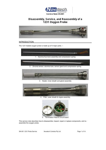
INTRODUCTION<br />
Service Note SN-001<br />
<strong>Disassembly</strong>, Service, and Reassembly <strong>of</strong> a<br />
<strong>1231</strong> <strong>Oxygen</strong> <strong>Probe</strong><br />
The <strong>1231</strong> heated oxygen probe is made up <strong>of</strong> 5 major parts: –<br />
1. Alumina four-bore assembly and compression spring<br />
2. Zirconia sensor, alumina tube, sensor gland and compression spring<br />
3. Heater, inner sheath and gland assembly<br />
4. Filter, outer sheath & nipple assembly<br />
5. Termination Head & circuit board<br />
This service note describes how to disassemble, inspect, repair or replace components, and reassemble<br />
<strong>the</strong> oxygen probe.<br />
SN-001 <strong>1231</strong> <strong>Probe</strong> Service <strong>Novatech</strong> <strong>Controls</strong> Pty Ltd Page 1 <strong>of</strong> 14
1.0 TOOLS REQUIRED<br />
To carry out <strong>the</strong>se procedures, <strong>the</strong> following tools are necessary: -<br />
• vice with an 80mm opening, and s<strong>of</strong>t jaws<br />
• 7/16” x 1/2” AF open end spanner<br />
• 7 mm open end spanner<br />
• 7 mm nut driver<br />
• 6.5 mm x 1.5 mm flat bladed screwdriver<br />
• 2.5 mm x 1.0 mm flat bladed screwdriver<br />
• 2 mm Allen key<br />
• 100 mm long nosed pliers<br />
2.0 TESTING<br />
It is recommended that before <strong>the</strong> probe is disassembled, it should be tested in a workshop.<br />
For <strong>the</strong> probe to be tested completely –<br />
1. Power must be applied to <strong>the</strong> heater and controlled to maintain about 720°C at <strong>the</strong> sensor.<br />
Expected result-<br />
The “SENSOR TEMP" should rise to 720°C ± 15°C within 15 minutes.<br />
The display <strong>of</strong> “SENSOR TEMP" should fluctuate less than 2°C.<br />
2. A certified gas connected to <strong>the</strong> “CAL” port <strong>of</strong> <strong>the</strong> probe (2 litres per minute), and <strong>the</strong> sensor EMF /<br />
<strong>Oxygen</strong> measured.<br />
Expected result-<br />
The oxygen reading from <strong>the</strong> probe should agree with <strong>the</strong> gas bottle’s certified value.<br />
3. The impedance <strong>of</strong> <strong>the</strong> sensor measured.<br />
Expected result-<br />
The impedance <strong>of</strong> <strong>the</strong> zirconia sensor as read on <strong>the</strong> analyser should be less than 7kΩ when <strong>the</strong><br />
sensor is 720°C ±15°C.<br />
The easiest way to do <strong>the</strong>se tests is to use a <strong>Novatech</strong> oxygen analyser. This provides all <strong>the</strong> facilities<br />
to do a complete electrical test <strong>of</strong> <strong>the</strong> probe.<br />
Alternatively, a common temperature controller and a 110VAC transformer could be used to control<br />
<strong>the</strong> temperature. A digital multimeter and <strong>the</strong> oxygen / EMF tables could be used to determine <strong>the</strong><br />
oxygen level. This does not give you <strong>the</strong> impedance <strong>of</strong> <strong>the</strong> sensor.<br />
SN-001 <strong>1231</strong> <strong>Probe</strong> Service <strong>Novatech</strong> <strong>Controls</strong> Pty Ltd Page 2 <strong>of</strong> 14
3.0 DISASSEMBLY PROCEDURE<br />
WARNING:<br />
The probe must NOT be disassembled while connected to an analyser. The heater<br />
terminals in <strong>the</strong> probe could have <strong>the</strong> 110 / 240 VAC mains voltages present.<br />
3.1 Hold probe vertically and securely by <strong>the</strong> hexagonal body in a vice with <strong>the</strong> probe connector at <strong>the</strong><br />
rear.<br />
3.2 Open <strong>the</strong> probe’s screwed head cover by turning <strong>the</strong> cap anti-clockwise.<br />
3.3 Hold <strong>the</strong> reference air hypodermic silicon tube while unscrewing <strong>the</strong> reference air male tube<br />
connector from <strong>the</strong> head to avoid twisting <strong>the</strong> silicon tube.<br />
3.4 When <strong>the</strong> reference air male connector is unscrewed from <strong>the</strong> head gently remove it from <strong>the</strong><br />
silicon tube.<br />
3.5 Remove <strong>the</strong> reference air hypodermic by lifting straight up. Do not bend. Sharp bends could<br />
cause a blockage in <strong>the</strong> tube.<br />
SN-001 <strong>1231</strong> <strong>Probe</strong> Service <strong>Novatech</strong> <strong>Controls</strong> Pty Ltd Page 3 <strong>of</strong> 14
3.6 From <strong>the</strong> circuit board, lift out <strong>the</strong> two-way heater wire connector and <strong>the</strong> 4-way O2 +ve, O2 –ve,<br />
T/C+ve and T/C-ve connector. Both connectors can be folded back outside <strong>the</strong> head for<br />
clearance.<br />
3.7 Remove <strong>the</strong> heater tail wires from <strong>the</strong> two way terminal by loosening <strong>the</strong> two screws.<br />
3.8 Remove <strong>the</strong> O2 +ve, T/C+ve and T/C-ve wires from <strong>the</strong> three way terminal by loosening <strong>the</strong> three<br />
screws.<br />
SN-001 <strong>1231</strong> <strong>Probe</strong> Service <strong>Novatech</strong> <strong>Controls</strong> Pty Ltd Page 4 <strong>of</strong> 14
3.9 Remove <strong>the</strong> earth lead wire. Access <strong>the</strong> M4 screw through <strong>the</strong> reference air male connector port.<br />
3.10 If installed, remove <strong>the</strong> wea<strong>the</strong>rpro<strong>of</strong> plug (head connector) by unscrewing (anti-clockwise).<br />
Avoid twisting <strong>the</strong> wires while unscrewing <strong>the</strong> connector<br />
SN-001 <strong>1231</strong> <strong>Probe</strong> Service <strong>Novatech</strong> <strong>Controls</strong> Pty Ltd Page 5 <strong>of</strong> 14
WARNING:<br />
The circuit board is held down against spring pressure by <strong>the</strong> two retaining nuts (M4<br />
Nylock). Release <strong>the</strong> circuit board evenly upwards to avoid damage to <strong>the</strong> ceramic<br />
four-bore tube. The ceramic tube is brittle and easily broken with sideways<br />
movement.<br />
3.11 Removed both circuit board retaining nuts.<br />
3.12 Lift <strong>the</strong> circuit board over <strong>the</strong> heater, O2 +ve, T/C +ve and T/C -ve wires.<br />
SN-001 <strong>1231</strong> <strong>Probe</strong> Service <strong>Novatech</strong> <strong>Controls</strong> Pty Ltd Page 6 <strong>of</strong> 14
3.13 Gently lift <strong>the</strong> ceramic four-bore straight up (avoid bending) until clear <strong>of</strong> <strong>the</strong> probe body.<br />
3.14 Set aside <strong>the</strong> four-bore in a safe place to avoid damage and contamination.<br />
3.15 Remove <strong>the</strong> sensor compression spring by gently working it from <strong>the</strong> sensor gland.<br />
3.16 Remove <strong>the</strong> sensor by holding <strong>the</strong> sensor gland with pliers and gently lifting it straight up<br />
(avoid bending) until clear <strong>of</strong> <strong>the</strong> probe body. Resistance will be felt removing <strong>the</strong> sensor due<br />
to <strong>the</strong> sensor gland o-ring seal. The sensor must not be forced, as it is brittle and easily<br />
broken.<br />
3.17 Set aside <strong>the</strong> sensor in a safe place to avoid damage and contamination.<br />
SN-001 <strong>1231</strong> <strong>Probe</strong> Service <strong>Novatech</strong> <strong>Controls</strong> Pty Ltd Page 7 <strong>of</strong> 14
3.18 Remove <strong>the</strong> probe head from <strong>the</strong> probe body by unscrewing <strong>the</strong> two retaining screws.<br />
3.19 Lift <strong>the</strong> inner sheath straight up and out <strong>of</strong> <strong>the</strong> outer sheath. Resistance will be felt removing<br />
<strong>the</strong> inner sheath due to <strong>the</strong> o-ring seal inside <strong>the</strong> hexagonal nipple. Once <strong>the</strong> o-ring is clear <strong>of</strong><br />
<strong>the</strong> hexagonal nipple, care must be taken removing <strong>the</strong> inner sheath. It must not be forced,<br />
but gently worked until clear <strong>of</strong> <strong>the</strong> outer sheath.<br />
3.20 Set aside <strong>the</strong> inner sheath in a safe place. The heater insulation must be protected from<br />
damage and contamination.<br />
The probe is now disassembled to <strong>the</strong> major subassemblies.<br />
SN-001 <strong>1231</strong> <strong>Probe</strong> Service <strong>Novatech</strong> <strong>Controls</strong> Pty Ltd Page 8 <strong>of</strong> 14
4.0 INSPECTION<br />
4.1 Outer Sheath<br />
Check for corrosion inside and outside especially near <strong>the</strong> hex nipple. This is where <strong>the</strong><br />
condensation <strong>of</strong> process gasses will cause <strong>the</strong> worst corrosion.<br />
4.2 Inner Sheath / Heater<br />
Check <strong>the</strong> heater continuity (approx. 110Ω).<br />
Check <strong>the</strong> heater insulation resistance (greater than 10MΩ).<br />
Check for signs <strong>of</strong> corrosion along <strong>the</strong> heater sheath.<br />
Check <strong>the</strong> o-ring for damage or wear.<br />
Check <strong>the</strong> tubular heater insulation for damage and degradation.<br />
4.3 Zirconia Sensor and Alumina tube<br />
Inspect <strong>the</strong> oxygen sensor for physical damage and loss <strong>of</strong> electrode paste.<br />
Check <strong>the</strong> o-rings for damage or wear.<br />
If <strong>the</strong> sensor is to be replaced use a flat faced drill (8mm) to remove any scale from <strong>the</strong> sensor<br />
seat to ensure a good electrical contact between <strong>the</strong> sensor and seat (O2 –ve).<br />
4.4 Thermocouple 4-bore<br />
Inspect <strong>the</strong> 4-bore for physical damage. Check <strong>the</strong> <strong>the</strong>rmocouple and O2 +ve conductor for<br />
continuity, and brittleness or oxidation <strong>of</strong> <strong>the</strong> wires.<br />
4.5 Head Assembly<br />
Check <strong>the</strong> reference air hypodermic for blockages.<br />
5.0 RE-ASSEMBLY<br />
5.1 Wipe a small amount <strong>of</strong> o-ring grease (such as Molykote FS3451) around <strong>the</strong> o-ring on <strong>the</strong><br />
gland body. Push <strong>the</strong> inner sheath straight into <strong>the</strong> outer sheath aligning <strong>the</strong> holes in <strong>the</strong> inner<br />
sheath assembly with <strong>the</strong> threaded holes in <strong>the</strong> outer sheath’s hexagonal nipple. Resistance<br />
will be felt replacing <strong>the</strong> inner sheath due to <strong>the</strong> o-ring seal inside <strong>the</strong> hexagonal nipple. Care<br />
must be taken replacing <strong>the</strong> inner sheath to prevent damaging <strong>the</strong> heater insulation and o-ring.<br />
It must not be forced, but gently worked into position.<br />
SN-001 <strong>1231</strong> <strong>Probe</strong> Service <strong>Novatech</strong> <strong>Controls</strong> Pty Ltd Page 9 <strong>of</strong> 14
5.2 Align <strong>the</strong> reference air male connector port in <strong>the</strong> head opposite <strong>the</strong> 1/8” NPT calibration port on<br />
<strong>the</strong> inner sheath assembly; screw <strong>the</strong> probe head to <strong>the</strong> probe body with <strong>the</strong> two retaining<br />
screws.<br />
5.3 Wipe a small amount <strong>of</strong> o-ring grease (such as Molykote FS3451) around <strong>the</strong> top <strong>of</strong> <strong>the</strong> sensor<br />
and outer o-ring on <strong>the</strong> sensor gland. Carefully insert <strong>the</strong> sensor into <strong>the</strong> inner sheath. Do not<br />
allow <strong>the</strong> tip <strong>of</strong> <strong>the</strong> sensor to contact <strong>the</strong> o-ring grease or <strong>the</strong> sensor will become<br />
contaminated. Use long nosed pliers to work <strong>the</strong> sensor gland and o-ring into <strong>the</strong> seal, do<br />
not use excessive force as this could damage <strong>the</strong> sensor.<br />
5.4 Replace <strong>the</strong> sensor compression spring onto <strong>the</strong> sensor gland.<br />
SN-001 <strong>1231</strong> <strong>Probe</strong> Service <strong>Novatech</strong> <strong>Controls</strong> Pty Ltd Page 10 <strong>of</strong> 14
5.5 Carefully insert <strong>the</strong> four-bore assembly into <strong>the</strong> sensor.<br />
5.6 Feed <strong>the</strong> four-bore wires through <strong>the</strong> circuit board centre hole and <strong>the</strong> heater wires through <strong>the</strong><br />
hole adjacent to <strong>the</strong> three-way connector. Install <strong>the</strong> reference air hypodermic into <strong>the</strong> four-bore<br />
insulator. While pushing <strong>the</strong> circuit board into position take extreme care lining up <strong>the</strong> four-bore<br />
spring and sensor compression spring to avoid breaking <strong>the</strong> four-bore insulator.<br />
SN-001 <strong>1231</strong> <strong>Probe</strong> Service <strong>Novatech</strong> <strong>Controls</strong> Pty Ltd Page 11 <strong>of</strong> 14
5.7 Replace both circuit board retaining nuts and flat washers.<br />
5.8 Replace <strong>the</strong> wea<strong>the</strong>rpro<strong>of</strong> plug (head connector). Avoid twisting <strong>the</strong> wires while screwing in <strong>the</strong><br />
connector.<br />
5.9 Pass a Philips head screwdriver through <strong>the</strong> reference air male connector port and attaché <strong>the</strong><br />
earth lead wire to <strong>the</strong> opposite side <strong>of</strong> <strong>the</strong> head with <strong>the</strong> M4 screw. Tighten securely.<br />
SN-001 <strong>1231</strong> <strong>Probe</strong> Service <strong>Novatech</strong> <strong>Controls</strong> Pty Ltd Page 12 <strong>of</strong> 14
5.10 Replace <strong>the</strong> O2 +ve (orange), T/C +ve (yellow) and T/C –ve (red) into <strong>the</strong> three way terminal<br />
block. The terminals are marked “O”, “R”, and “Y”.<br />
5.11 Replace <strong>the</strong> heater wires into <strong>the</strong> two-way terminal block. These leads are not polarised.<br />
5.12 Plug in <strong>the</strong> two wire heater connector and four way sensor / T/C connector.<br />
SN-001 <strong>1231</strong> <strong>Probe</strong> Service <strong>Novatech</strong> <strong>Controls</strong> Pty Ltd Page 13 <strong>of</strong> 14
5.13 Before screwing <strong>the</strong> reference air male connector into <strong>the</strong> head be sure <strong>the</strong> hypodermic is<br />
inserted into <strong>the</strong> barb’s hole. Tighten <strong>the</strong> male connector and <strong>the</strong>n slide <strong>the</strong> silicon sleeve over<br />
<strong>the</strong> barb connector to form a seal.<br />
5.14 Install <strong>the</strong> screw top lid and tighten using <strong>the</strong> castellated slots on <strong>the</strong> lid.<br />
The probe can now be tested as in section 2.0<br />
SN-001 <strong>1231</strong> <strong>Probe</strong> Service <strong>Novatech</strong> <strong>Controls</strong> Pty Ltd Page 14 <strong>of</strong> 14


