- Page 1 and 2: Copyright by Todd Christopher Baile
- Page 3 and 4: Imprint Template Advances and Surfa
- Page 5 and 6: Dedication This is dedicated to my
- Page 7 and 8: I want to thank those who aided in
- Page 9 and 10: mitigation of the shift in feature
- Page 11 and 12: Chapter 4: Review of the Reaction o
- Page 13 and 14: Appendix D: Conversion of KLA Data
- Page 15 and 16: List of Figures Figure 1.1. Schemat
- Page 17 and 18: Figure 5.3: Water contact angle and
- Page 19 and 20: Figure 7.25: Images captured during
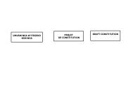
- Page 21 and 22: Figure B.8: Program diagram for Swi
- Page 23 and 24: “source” and “drain” region
- Page 25 and 26: computing power is required. Microp
- Page 27 and 28: Photoresist Substrate Mask hυ hυ
- Page 29 and 30: Tool Price ($) $100,000,000 $10,000
- Page 31 and 32: material. This material takes the s
- Page 33 and 34: planarizing/transfer layer was coat
- Page 35 and 36: patterned relief structures is alig
- Page 37 and 38: Contact lithography predates the pr
- Page 39: 8. Chou, S.Y., P.R. Krauss, and P.J
- Page 43 and 44: substrate that changes in chemical
- Page 45 and 46: In modern photomask production, imp
- Page 47 and 48: and CD-SEM inspection, and also all
- Page 49 and 50: Requirements for Transparent Conduc
- Page 51 and 52: quartz substrates. Percent transmis
- Page 53 and 54: a) b) Figure 2.5: (a) 30 nm trenche
- Page 55 and 56: nm, so the normalization to film th
- Page 57 and 58: with increasing anneal time, up to
- Page 59 and 60: 2.12 shows line/space features poss
- Page 61 and 62: a) b) Figure 2.14: SEM micrographs
- Page 63 and 64: a) c) e) Index Index Index 2.7 2.5
- Page 65 and 66: function of ITO thickness is much g
- Page 67 and 68: esidual layer only. The right plot
- Page 69 and 70: it is mentioned here for context. T
- Page 71 and 72: Some results are shown in Figure 2.
- Page 73 and 74: 5. Widden, T.K., et al., Nanotechno
- Page 75 and 76: 45. Lewis, B.G. and D.C. Paine, MRS
- Page 77 and 78: 3.1 BACKGROUND Chapter 3: SFIL Etch
- Page 79 and 80: 3.2 EXPERIMENTAL For the imprinting
- Page 81 and 82: The fluorinated additive experiment
- Page 83 and 84: Formulation M2 did not polymerize.
- Page 85 and 86: adhesive forces at the two interfac
- Page 87 and 88: Chapter 4: Review of the Reaction o
- Page 89 and 90: such as annealing. Each of these ex
- Page 91 and 92:
on colloidal silica particles. 9 He
- Page 93 and 94:
Figure 4.2: From Chuang, et al. 16
- Page 95 and 96:
was achieved by exposing the surfac
- Page 97 and 98:
Cras, et al. 37 compared various we
- Page 99 and 100:
where X is either an alkoxy group o
- Page 101 and 102:
with increasing temperature. They a
- Page 103 and 104:
from liquid and supercritical CO2.
- Page 105 and 106:
hydrolyzed intermediates. These res
- Page 107 and 108:
limiting film thickness. This is in
- Page 109 and 110:
authors observed a decrease in the
- Page 111 and 112:
to form SAM films of at least moder
- Page 113 and 114:
was able to predict the networking
- Page 115 and 116:
39. Ruzyllo, J., et al., Proc. Elec
- Page 117 and 118:
77. Allara, D., A.N. Parikh, and F.
- Page 119 and 120:
Chapter 5: SFIL Imprint Template Re
- Page 121 and 122:
5.1.3 Self-Assembled Monolayer Rele
- Page 123 and 124:
ITO, followed by plasma-enhanced ch
- Page 125 and 126:
5.3 RESULTS AND DISCUSSION 5.3.1 Fu
- Page 127 and 128:
a) b) Water Contact Angle F:Si Area
- Page 129 and 130:
Imprinting Durability of FOTS on Fu
- Page 131 and 132:
At the time of this writing, no oth
- Page 133 and 134:
Methanol adsorption below 130 K fol
- Page 135 and 136:
of the SiO2 layer to define the tem
- Page 137 and 138:
treatment films of at least modest
- Page 139 and 140:
imprinting durability. Due to the r
- Page 141 and 142:
Chapter 6: Effect of Substrate Hydr
- Page 143 and 144:
The Ag 3d5/2 XPS peak at 368.3 eV f
- Page 145 and 146:
dθ Equation 6.8 ( ) 2 OH , 3 3 −
- Page 147 and 148:
Concentration (nm -2 ) 5 4.5 4 3.5
- Page 149 and 150:
Mass (mg) 14 13.9 13.8 13.7 13.6 13
- Page 151 and 152:
silanol coverage for temperatures b
- Page 153 and 154:
increasing film density with increa
- Page 155 and 156:
7.1 INTRODUCTION DEFECT ANALYSIS FO
- Page 157 and 158:
The fundamental question to be answ
- Page 159 and 160:
placement in the die array must be
- Page 161 and 162:
an exposure source that is used to
- Page 163 and 164:
the transfer layer. The BARC was sp
- Page 165 and 166:
Figure 7.5: UT MER South cleanroom
- Page 167 and 168:
English rating denotes the number o
- Page 169 and 170:
wall of the cleanroom was a large c
- Page 171 and 172:
The results of the particles genera
- Page 173 and 174:
the wafer chuck, and we have attemp
- Page 175 and 176:
7.4 RESULTS & DISCUSSION 7.4.1 Temp
- Page 177 and 178:
a) that protects the master from co
- Page 179 and 180:
determines the absolute value of co
- Page 181 and 182:
a) b) c) Figure 7.16: Resist images
- Page 183 and 184:
Figure 7.18: Evolution of slope (so
- Page 185 and 186:
Figure 7.19: SSE for the data in Fi
- Page 187 and 188:
and 92 in the denominator is 3.95;
- Page 189 and 190:
a) b) Figure 7.22: (a) Obvious patt
- Page 191 and 192:
Table 7.1: Percent standard error i
- Page 193 and 194:
a) c) e) Defect Density (cm -2 ) De
- Page 195 and 196:
defect bins reveal an increase in d
- Page 197 and 198:
detected defects in one particular
- Page 199 and 200:
imprints show little or no increase
- Page 201 and 202:
a) b) Defect Density (cm -2 ) Defec
- Page 203 and 204:
Figure 7.35 shows a defect composed
- Page 205 and 206:
a) b) c) d) e) f) g) h) i) j) k) Fi
- Page 207 and 208:
a) b) c) Figure 7.34: Example defec
- Page 209 and 210:
a) b) c) Figure 7.36: Example defec
- Page 211 and 212:
Figure 7.37: Stress-strain comparis
- Page 213 and 214:
7.6 CONCLUSIONS The SFIL cleanroom
- Page 215 and 216:
Chapter 8: Effect of Film thickness
- Page 217 and 218:
8.2 EXPERIMENTAL A Woollam M-2000 s
- Page 219 and 220:
a) b) Figure 8.4. (a) Irradiance sp
- Page 221 and 222:
intensity of the Xe lamp, and RspCC
- Page 223 and 224:
a) b) Contrast Contrast 10 9 8 7 6
- Page 225 and 226:
a) b) Figure 8.7. Contrast response
- Page 227 and 228:
a) b) c) Transfer Layer Thickness (
- Page 229 and 230:
contrast prior to subsequent etchin
- Page 231 and 232:
The etch barrier imprinting fidelit
- Page 233 and 234:
evaluation needs to be undertaken t
- Page 235 and 236:
where η0 and ηm are the optical a
- Page 237 and 238:
N_SiO2 = SiO2(2,2:3); t_SiO2 = 100;
- Page 239 and 240:
SFILCalc.m function data = SFILcalc
- Page 241 and 242:
function [a] = phase(lambda,N,H,thi
- Page 243 and 244:
Figure B.1: Picture of the surface
- Page 245 and 246:
An Omega type K thermocouple is con
- Page 247 and 248:
Figure B.2: Diagram of surface trea
- Page 249 and 250:
Figure B.3: User interface for the
- Page 251 and 252:
option when the program is started
- Page 253 and 254:
Figure B.7: Various subVIs called b
- Page 255 and 256:
Figure B.10: Program diagram for Ch
- Page 257 and 258:
The Auto program uses these same su
- Page 259 and 260:
Figure C.1: Force balance diagram f
- Page 261 and 262:
Figure C.2: Plot of cos θ vs. γlv
- Page 263 and 264:
Figure C.4: Plot of cos θ vs. γlv
- Page 265 and 266:
Equation C.8 which upon rearrangeme
- Page 267 and 268:
and electron-donor (γ - ) paramete
- Page 269 and 270:
where θ0 is the contact angle in v
- Page 271 and 272:
Kwok, et al reinforce the relation
- Page 273 and 274:
Figure C.7: Correlation between mea
- Page 275 and 276:
If one requires only an estimation
- Page 277 and 278:
32. Kwok, D.Y., et al., Langmuir, 1
- Page 279 and 280:
a separate delimited text file for
- Page 281 and 282:
2 -2 M -1 1; AreaPerTest 1.20197e+0
- Page 283 and 284:
ins1 = strcat('< ',num2str(edges(2)
- Page 285 and 286:
n(2) = n(2) + 1; case 3 n(3) = n(3)
- Page 287 and 288:
Appendix E: Estimation of Downstrea
- Page 289 and 290:
Figure E.1: Experimental FTIR appar
- Page 291 and 292:
Figure E.2: Vapor pressure apparatu
- Page 293 and 294:
Absorbance 0.16 0.14 0.12 0.1 0.08
- Page 295 and 296:
Absorbance 0.3 0.25 0.2 0.15 0.1 0.
- Page 297 and 298:
Absorbance 2.45 1.95 1.45 0.95 0.45
- Page 299 and 300:
Figure E.9: Comparison of experimen
- Page 301 and 302:
ln(Psat (Torr)) 1.5 1 0.5 0 -0.5 -1
- Page 303 and 304:
FOTS Concentration (mol/liter) 2.0E
- Page 305 and 306:
Bouwhuis, G., et al., Principles of
- Page 307 and 308:
Constantine, C., R. Westerman, and
- Page 309 and 310:
Gun'ko, V.M., et al., Inter. J. Mas
- Page 311 and 312:
Lee, L.-H., J. Coll. Int. Sci., 199
- Page 313 and 314:
Pellerite, M.J., E.J. Wood, and V.W
- Page 315 and 316:
The Aldrich Library of FT-IR Spectr
- Page 317:
VITA Todd Christopher Bailey was bo