
You also want an ePaper? Increase the reach of your titles
YUMPU automatically turns print PDFs into web optimized ePapers that Google loves.
<strong>Tilt</strong>-up <strong>Technical</strong> <strong>Manual</strong><br />
www.MeadowBurke.com<br />
Insert Placement<br />
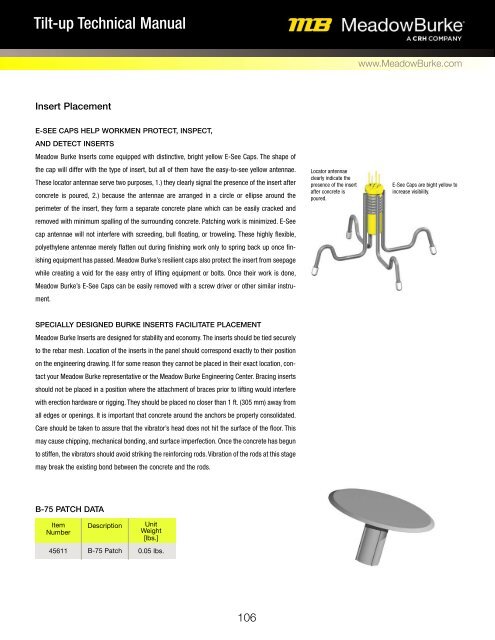
E-SEE CAPS HELP WORKMEN PROTECT, INSPECT,<br />
AND DETECT INSERTS<br />
Meadow Burke Inserts come equipped with distinctive, bright yellow E-See Caps. The shape of<br />
the cap will differ with the type of insert, but all of them have the easy-to-see yellow antennae.<br />
These locator antennae serve two purposes, 1.) they clearly signal the presence of the insert after<br />
concrete is poured, 2.) because the antennae are arranged in a circle or ellipse around the<br />
perimeter of the insert, they form a separate concrete plane which can be easily cracked and<br />
removed with minimum spalling of the surrounding concrete. Patching work is minimized. E-See<br />
cap antennae will not interfere with screeding, bull floating, or troweling. These highly flexible,<br />
polyethylene antennae merely flatten out during finishing work only to spring back up once finishing<br />
equipment has passed. Meadow Burke’s resilient caps also protect the insert from seepage<br />
while creating a void for the easy entry of lifting equipment or bolts. Once their work is done,<br />
Meadow Burke’s E-See Caps can be easily removed with a screw driver or other similar instrument.<br />
Locator antennae<br />
clearly indicate the<br />
presence of the insert<br />
after concrete is<br />
poured.<br />
E-See Caps are bight yellow to<br />
increase visibility.<br />
SPECIALLY DESIGNED BURKE INSERTS FACILITATE PLACEMENT<br />
Meadow Burke Inserts are designed for stability and economy. The inserts should be tied securely<br />
to the rebar mesh. Location of the inserts in the panel should correspond exactly to their position<br />
on the engineering drawing. If for some reason they cannot be placed in their exact location, contact<br />
your Meadow Burke representative or the Meadow Burke Engineering Center. Bracing inserts<br />
should not be placed in a position where the attachment of braces prior to lifting would interfere<br />
with erection hardware or rigging. They should be placed no closer than 1 ft. (305 mm) away from<br />
all edges or openings. It is important that concrete around the anchors be properly consolidated.<br />
Care should be taken to assure that the vibrator’s head does not hit the surface of the floor. This<br />
may cause chipping, mechanical bonding, and surface imperfection. Once the concrete has begun<br />
to stiffen, the vibrators should avoid striking the reinforcing rods. Vibration of the rods at this stage<br />
may break the existing bond between the concrete and the rods.<br />
B-75 PATCH DATA<br />
Item<br />
Number<br />
45611<br />
Description<br />
B-75 Patch<br />
Unit<br />
Weight<br />
[lbs.]<br />
0.05 lbs.<br />
106