
You also want an ePaper? Increase the reach of your titles
YUMPU automatically turns print PDFs into web optimized ePapers that Google loves.
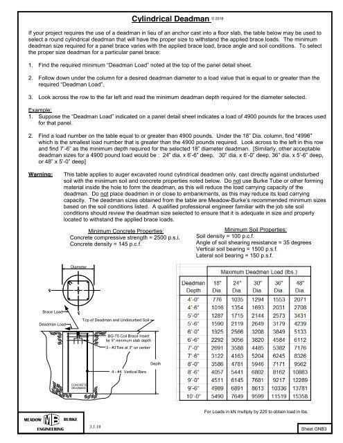
Cylindrical Deadman © 2018<br />
If your project requires the use of a deadman in lieu of an anchor cast into a floor slab, the table below may be used to<br />
select a round cylindrical deadman that will have the proper size to withstand the applied brace loads. The minimum<br />
deadman size required for a panel brace varies with the applied brace load, brace angle and soil conditions. To select<br />
the proper size deadman for a particular panel brace:<br />
1. Find the required minimum “Deadman Load” noted at the top of the panel detail sheet.<br />
2. Follow down under the column for a desired deadman diameter to a load value that is equal to or greater than the<br />
required “Deadman Load”.<br />
3. Look across the row to the far left and read the minimum deadman depth required for the diameter selected.<br />
Example:<br />
1. Suppose the “Deadman Load” indicated on a panel detail sheet indicates a load of 4900 pounds for the braces used<br />
for that panel.<br />
2. Find a load number on the table equal to or greater than 4900 pounds. Under the 18” Dia. column, find “4996”<br />
which is the smallest load number that is greater than the 4900 pounds required. Look across to the left in this row<br />
and find 7’-6” as the minimum depth required for the selected 18” diameter deadman. [Similarly, other acceptable<br />
deadman sizes for a 4900 pound load would be : 24” dia. x 6’-6” deep, 30” dia. x 6’-0” deep, 36” dia. x 5’-6” deep,<br />
or 48” x 5’-0” deep]<br />
Warning:<br />
This table applies to auger excavated round cylindrical deadmen only, cast directly against undisturbed<br />
soil with the minimum soil and concrete properties noted below. Do not use Burke Tube or other forming<br />
material inside the hole to form the deadman, as this will reduce the load carrying capacity of the<br />
deadman. Do not place deadmen in or close to embankments, as this may reduce its load carrying<br />
capacity. The deadman sizes obtained from the table are Meadow-Burke’s recommended minimum sizes<br />
based on the soil conditions listed. A qualified professional engineer familiar with the job site soil<br />
conditions should review the deadman size selected to ensure that it is adequate in size and properly<br />
located to withstand the applied brace loads.<br />
Minimum Concrete Properties:<br />
Concrete compressive strength = 2500 p.s.i.<br />
Concrete density = 145 p.c.f.<br />
Minimum Soil Properties:<br />
Soil density = 100 p.c.f.<br />
Angle of soil shearing resistance = 35 degrees<br />
Vertical soil bearing = 1500 p.s.f.<br />
Lateral soil bearing = 150 p.s.f.<br />
Diameter<br />
c L c L<br />
Brace Load<br />
c L c L<br />
Deadman Load<br />
Top of Deadman and Undisturbed Soil<br />
BG-75 Coil Brace Insert<br />
for 5" minimum slab depth<br />
3 - #3Ties at 3" on center<br />
4 - #4 Vertical Bars<br />
Depth<br />
CONCRETE<br />
DEADMAN<br />
MEADOW<br />
ENGINEERING<br />
BURKE<br />
3.1.18<br />
For Loads in kN multiply by 225 to obtain load in lbs.<br />
Sheet GNB3