
Create successful ePaper yourself
Turn your PDF publications into a flip-book with our unique Google optimized e-Paper software.
<strong>Tilt</strong>-up <strong>Technical</strong> <strong>Manual</strong><br />
www.MeadowBurke.com<br />
Brace Table Legend<br />
The following brace spacing tables have been designed for an 80 mph ultimate wind with a 1 year mean recurrence interval. Spacings are assuming<br />
a solid panel with a panel width not less than 20 feet. For more accurate spacings that factor in actual panel shape and openings contact<br />
Meadow Burke Engineering. The table should be used in conjunction with the notes and recommendations shown in the Brace Design Notes,<br />
on pages 78,79, & 80.<br />
SFF = Maximum brace spacing for a panel with a height below floor (or top of deadman when used) equal to “FF” feet. [ie., the S 0 column yields<br />
the maximum spacing for a panel with no height below floor, the S2 column yields the maximum spacing for a panel 2 foot maximum height below<br />
floor, etc.]<br />
All dimensions are shown in units of feet. Always round the dimensions for the panel height below floor and the panel height above floor, to the next<br />
larger chart value. Reference brace detail on Brace Design Notes, on page 78.<br />
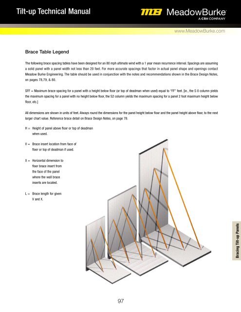
H = Height of panel above floor or top of deadman<br />
when used.<br />
V = Brace insert location from face of<br />
floor or top of deadman if used.<br />
X = Horizontal dimension to<br />
floor brace insert from<br />
the face of the panel<br />
where the wall brace<br />
inserts are located.<br />
L = Brace length for given<br />
V and X.<br />
Bracing <strong>Tilt</strong>-up Panels<br />
97