
Create successful ePaper yourself
Turn your PDF publications into a flip-book with our unique Google optimized e-Paper software.
<strong>Tilt</strong>-up <strong>Technical</strong> <strong>Manual</strong><br />
www.MeadowBurke.com<br />
INSTALLATION<br />
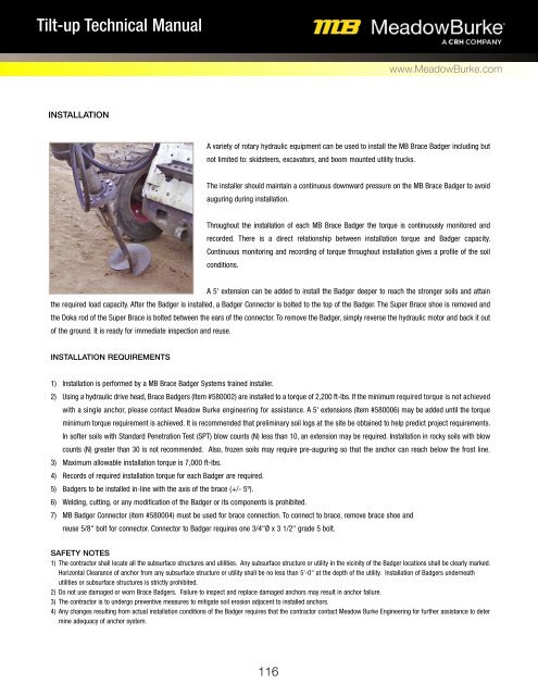
A variety of rotary hydraulic equipment can be used to install the MB Brace Badger including but<br />
not limited to: skidsteers, excavators, and boom mounted utility trucks.<br />
The installer should maintain a continuous downward pressure on the MB Brace Badger to avoid<br />
auguring during installation.<br />
Throughout the installation of each MB Brace Badger the torque is continuously monitored and<br />
recorded. There is a direct relationship between installation torque and Badger capacity.<br />
Continuous monitoring and recording of torque throughout installation gives a profile of the soil<br />
conditions.<br />
A 5' extension can be added to install the Badger deeper to reach the stronger soils and attain<br />
the required load capacity. After the Badger is installed, a Badger Connector is bolted to the top of the Badger. The Super Brace shoe is removed and<br />
the Doka rod of the Super Brace is bolted between the ears of the connector. To remove the Badger, simply reverse the hydraulic motor and back it out<br />
of the ground. It is ready for immediate inspection and reuse.<br />
INSTALLATION REQUIREMENTS<br />
1) Installation is performed by a MB Brace Badger Systems trained installer.<br />
2) Using a hydraulic drive head, Brace Badgers (Item #580002) are installed to a torque of 2,200 ft-lbs. If the minimum required torque is not achieved<br />
with a single anchor, please contact Meadow Burke engineering for assistance. A 5' extensions (Item #580006) may be added until the torque<br />
minimum torque requirement is achieved. It is recommended that preliminary soil logs at the site be obtained to help predict project requirements.<br />
In softer soils with Standard Penetration Test (SPT) blow counts (N) less than 10, an extension may be required. Installation in rocky soils with blow<br />
counts (N) greater than 30 is not recommended. Also, frozen soils may require pre-auguring so that the anchor can reach below the frost line.<br />
3) Maximum allowable installation torque is 7,000 ft-lbs.<br />
4) Records of required installation torque for each Badger are required.<br />
5) Badgers to be installed in-line with the axis of the brace (+/- 5º).<br />
6) Welding, cutting, or any modification of the Badger or its components is prohibited.<br />
7) MB Badger Connector (item #580004) must be used for brace connection. To connect to brace, remove brace shoe and<br />
reuse 5/8" bolt for connector. Connector to Badger requires one 3/4"Ø x 3 1/2" grade 5 bolt.<br />
SAFETY NOTES<br />
1) The contractor shall locate all the subsurface structures and utilities. Any subsurface structure or utility in the vicinity of the Badger locations shall be clearly marked.<br />
Horizontal Clearance of anchor from any subsurface structure or utility shall be no less than 5'-0" at the depth of the utility. Installation of Badgers underneath<br />
utilities or subsurface structures is strictly prohibited.<br />
2) Do not use damaged or worn Brace Badgers. Failure to inspect and replace damaged anchors may result in anchor failure.<br />
3) The contractor is to undergo preventive measures to mitigate soil erosion adjacent to installed anchors.<br />
4) Any changes resulting from actual installation conditions of the Badger requires that the contractor contact Meadow Burke Engineering for further assistance to deter<br />
mine adequacy of anchor system.<br />
116