Prosthetic Arm Force Reducer Team 1 – Halliday's ... - Ohio University
Prosthetic Arm Force Reducer Team 1 – Halliday's ... - Ohio University
Prosthetic Arm Force Reducer Team 1 – Halliday's ... - Ohio University

Create successful ePaper yourself
Turn your PDF publications into a flip-book with our unique Google optimized e-Paper software.
<strong>Prosthetic</strong> <strong>Arm</strong> <strong>Force</strong> <strong>Reducer</strong><br />
<strong>Team</strong> 1 <strong>–</strong> Halliday’s Heroes<br />
<strong>Team</strong> Members:<br />
Dan Cole<br />
Jay Duffy<br />
Greg Harvey<br />
Josh Hlebak<br />
Michael Massey<br />
Lisa Molitoris<br />
Lou Monnier<br />
Lena Richards<br />
Monday, June 9 th , 2008<br />
Abstract:<br />
There is a need for an assistive technology device that focuses on extremity loss above the elbow<br />
within the field of agriculture. Our focus is with farmers who have physically demanding jobs to<br />
be able to perform tasks which require reliable simulated usage of the appendage and therefore,<br />
continue to run a profitable farm operation. The main goals of this device are to increase the<br />
potential grip strength of the prosthetic, reduce the necessary input force and therefore physical<br />
strain, and make the device serviceable enough that any maintenance can be done by the<br />
customer. A prosthetic arm force reducer was manufactured by designing a pulley mechanical<br />
advantage system housed within the hollow forearm section of the prosthetic. The system<br />
reduces the input force required by the user by 47% from 18 lbs to 9.5 lbs and costs only 9.6% or<br />
an additional $575 dollars of the total prosthetic arm.
Table of Contents Page Page<br />
1.0 Introduction………………………………………………………………………………....3<br />
1.1 Initial Needs Statement…………………………………………………………..…3<br />
2.0 Customer Needs Assessment………………………………………………………….…....3<br />
2.1 Weighting of Customer Needs……………………………………….......................5<br />
3.0 Revised Need Statement and Target Specifications…………………………………..……5<br />
4.0 External Search……………………………………………………………….…………….7<br />
4.1 Benchmarking……………………………………………………………………....8<br />
4.2 Application Patents………………………………………………………………..14<br />
4.3 Application Standards……………………………………………………………..15<br />
4.4 Application Constraints…………………………………………………………...16<br />
5.0 Concept Generation……………………………………………………………………….17<br />
5.1 Concept Generation……………………………………………………………….17<br />
5.2 Concept Development, Scoring and Selection……………………………….……21<br />
6.0 Concept Selection…………………………………………………………………………23<br />
6.1 Data and Calculations for Feasibility and Effectiveness Analysis………………..23<br />
6.2 Concept Development, Scoring and Selection…………………………………….28<br />
7.0 Final Design…………………………………………………………………………….....29<br />
7.1 System Personalization and Operation…………………………………………....40<br />
7.2 How is it Manufactured...........................................................................................40<br />
7.3 Cost Analysis & Bill of Materials…………………………………………………45<br />
7.4 Design Validation…………………………………………………………………47<br />
8.0 Conclusion………………………………………………………………………...………48<br />
Appendix A <strong>–</strong> Split Hook Sample Calculation…………………………………………………..51<br />
Appendix B <strong>–</strong> Interview Summaries……………………………………………………………..52<br />
Appendix C <strong>–</strong> Tim Lang’s Forearm Dimensions & Data………………………………………..55<br />
References………………………………………………………………………………………..56<br />
2
1.0 Introduction<br />
Limb loss generally refers to the absence of any part of an extremity due to surgical or traumatic<br />
amputation (Amputee Coalition of America 2008). Upper limb loss accounts for about 30% of<br />
the 350,000 persons with amputations in the United States (Kulley 2008). There are also multiple<br />
causes for upper limb loss such as disease, traumatic accidents, infections, and tumors.<br />
The field of agriculture is a very dangerous work environment with heavy equipment and many<br />
chances for accidents. Farming accidents are a common cause of upper limb loss that can put<br />
many farmers out of work. We would like to work with a farmer to develop an upgrade to the<br />
current prosthetic systems in use which would be able to assist that farmer in their daily work.<br />
Important objectives of the design project involve:<br />
• Full customer research to determine all the positives and negatives of the current system<br />
• Full benchmarking research to determine what has been attempted already and what has<br />
or has not worked<br />
• Solving the customers main needs with as little manufacturing and complexity as possible<br />
Through research, feedback, and further design our goal is to meet our objectives and design an<br />
assistive device for people with upper arm loss, specifically in the field of agriculture. A high<br />
standard of excellence will be put forth on all our efforts reflecting our strong team work,<br />
willingness, enthusiasm, and genuine interest to improve workplace conditions for people with<br />
disabilities.<br />
1.1 Initial Needs Statement<br />
There is a need for assistive technology devices that reduce barriers that prevent persons with<br />
severe disabilities from entering or advancing in the workplace. Devices are needed to address<br />
environmental accommodation, functional assistance, and mobility issues for people with<br />
cognitive disabilities, developmental disabilities, and physical impairments (vision, hearing and<br />
mobility) (NISH National Scholar Award for Workplace Innovation & Design 2007/2008).<br />
2.0 Customer Needs Assessment<br />
A customer has been identified who has upper limb loss above the elbow of his right arm. Our<br />
customer, Tim Lang, operates a dairy farm in Marietta, <strong>Ohio</strong> and lost his right arm<br />
approximately two years ago. Now that Tim has a prosthetic arm he is able to continue operating<br />
his farm, but with physical discomfort and difficulties. Through interviews (See Appendix A)<br />
and meetings with him as well as rehabilitation engineers, vocational supervisors, and prosthetic<br />
suppliers we have compiled a list of design features that would aid him in his daily farming tasks<br />
(See Table 2.0.1).<br />
Our customer has identified physical discomfort as his biggest problem with his prosthetic<br />
followed by a desire to have increased grip strength and lastly to make the device easy enough to<br />
fix that he himself could make repairs to it without having to send it in to a specialized<br />
prosthetics manufacturer. In order to weight our needs, the Analytical Hierarchy Process was<br />
3
used for three main categories. These categories consist of user friendly, reliable, and affordable.<br />
The contents of these categories can be found in Table 2.0.2 below.<br />
Table 2.0.1 - Initial Customer Needs List Obtained<br />
From Interviews and Observations<br />
Reduced user input force<br />
Increased grip strength<br />
Reliable<br />
Durable<br />
Servicable<br />
Light weight<br />
Corrosion resistant<br />
Simple to use<br />
Affordable<br />
Minimal maintance<br />
Rugged<br />
Adaptable to current prosthetic<br />
Optimal size for best operation<br />
Doesn't add too much cable travel<br />
Safe<br />
Table 2.0.2 - Hierarchal Customer Needs List<br />
1. User friendly<br />
1.1 Reduced user input force<br />
1.2 Increased grip strength<br />
1.3 Simple to use<br />
1.4 Doesn't add too much cable travel<br />
1.5 Light weight<br />
1.6 Safe<br />
1.7 Adaptable to current prosthetic<br />
1.8 Optimal size for best operation<br />
2. Reliable<br />
2.1 Durable<br />
2.2 Servicable<br />
2.3 Minimal maintance<br />
2.4 Corrosion resistant<br />
2.5 Rugged<br />
3. Affordable<br />
3.1 Low manufacturing costs<br />
4
2.1 Weighting of Customer Needs<br />
Weighting the customer needs is a key part of engineering before the design process. By<br />
weighting the needs, one can see the most important aspects of the project which will make<br />
further design decisions easier and more consistent. The weighting should also be directly<br />
related to the customer’s needs and desires as well. This assures that the customer will be happy<br />
with the final result.<br />
After weighting our project, it was determined that the reliable and user friendly categories were<br />
the most important needs of our project and customer. The breakdown of these needs can be<br />
found in Table 2.1.1 below.<br />
Table 2.1.1 - Analytical Hierarchy Process Breakdown<br />
User Friendly Reliable Affordable<br />
User Friendly 1.00 1.00 1.00<br />
Reliable 1.00 1.00 1.00<br />
Affordable 3.00 3.00 1.00<br />
Total 6.00 6.00 4.00<br />
Weight 0.333 0.333 0.222<br />
3.0 Revised Need Statement and Target Specifications<br />
There is a need for an assistive technology device that specifically focuses on upper-extremity<br />
loss above the elbow within the field of agriculture. Our particular focus will be farmers who<br />
have physically demanding jobs to be able to perform tasks which require reliable simulated<br />
usage of the appendage and therefore, continue to run a profitable farm operation. “Health<br />
professionals and others who have contact with farmers with disabilities need to be cognizant of<br />
the strong desire and continued ability to farm after severe injury. More attention should be<br />
given to farm-specific occupational rehabilitation programs, such as AgrAbility, and in the<br />
engineering of prostheses and other assistive technology.” (Reed & Claunch 1998)<br />
This need exists due to the prevalence of disabling injuries in agriculture due to farming being an<br />
incredibly dangerous profession. Theses persons with upper extremity loss within the field of<br />
agriculture need a specific prosthetic to continue working properly and efficiently in their daily<br />
farming tasks. In order for farmers to continue their livelihood, increasing the ease of use, grip<br />
strength, and serviceability of a standard prosthetic will be our main focus.<br />
To reduce to the physical impact on the user’s body and the amount of input force required to<br />
open the hooks, improved comfort and ease of use will be the main focal point. Also, many<br />
current available prosthetics are not robust enough nor have a sufficient gripping force to meet<br />
the demands of users who work in physically intensive occupations. Increasing the grip force of<br />
a standard split hook at the contact point(s) of the grippers will address this need for increased<br />
grip strength. Serviceability will be addressed by the maintenance being able to be performed<br />
easily by the customer.<br />
5
Table 3.0.1 <strong>–</strong> Customer Needs List<br />
Need # Need (In Order of Importance)<br />
1 Manageable input force<br />
2 Increased grip force<br />
3 Serviceability<br />
4 Reliability<br />
5 Affordability (under $700 US)<br />
6 Corrosion Resistance<br />
7 Light weight (Less than 5 lbs)<br />
8 Simplicity of operation (No electrical components)<br />
Table 3.0.2 <strong>–</strong> Needs Metric List<br />
Metric Need # Metric Importance # Units<br />
#<br />
(3 High, 1 Low)<br />
1 1,2,8 Input force 3 lbs<br />
2 1,2 Closing force 3 lbs<br />
3 all Unit price 2 $<br />
4 3,8 Unit dimensions 1 in<br />
5 1,2,3,4,6,8 Unit life 3 #cycles<br />
6 7,8 Unit weight 2 lbs<br />
USpecification quantities include:<br />
1. UInput forceU: A one-half decrease in input force is necessary. The input force to operate<br />
the prosthetic is human input: the user’s shrugs their shoulders, moving the cable. This<br />
cable is attached to the back harness and runs down the arm to the terminal device.<br />
This one-half decrease is necessary because the user has complained of nightly<br />
discomfort from using his current split-hook loaded with many rubber bands (up to 7).<br />
2. UClosing forceU: Enough closing force must be provided for the user to hold a nail steady<br />
and nail it into a wall. The closing force must be greater than or equal to a traditional<br />
spilt hook utilizing 7 rubber bands of tension.<br />
3. Unit priceU: A typical sized split hook prosthetic device made of stainless steel costs about<br />
$565 - 1,100 dollars. The entire mechanical advantage system will ideally cost under<br />
$700 which corresponds to bottom quarter of the price range.<br />
4. Unit dimensionsU: Our system must fit into the user’s existing forearm prosthetic. In<br />
order to ensure safe operation, there shall be no extraneous parts attached to the forearm.<br />
5. Unit lifeU: The unit life will be based on stainless steel being the favorable material for the<br />
mechanical advantage components because of its strength and corrosion resistant<br />
characteristics. An operating temperature range of -30 to 120˚F has also been specified,<br />
6
which could limit the use of rubber bands. The life specified should be at least 3 years or<br />
10,800 cycles (360 working days a year with 10 cycles per day).<br />
6. Unit weightU: A typical split-hook terminal device plus forearm section weighs about 2<br />
pounds. Since this project is concerned with enhancing functionality, some extra amount<br />
of weight will likely be incurred by the modifications. Our maximum weight is to stay<br />
under 5 pounds (approximately the weight of an average adult forearm and hand). The<br />
customer has added that extra weight will not act as a hindrance. The internally located<br />
mechanical advantage system will instead increase the strength of his currently hollow<br />
forearm section.<br />
4.0 External Search<br />
The Disability Act of 1990 was monumental in creating equal opportunities for people with<br />
disabilities. Though this act has made significant progress, only 25% of people between the ages<br />
of 16 to 64 (commonly considered as the working age demographic) with disabilities are<br />
employed. Of the remaining 75%, two-thirds of them wish they were employed (Health<br />
Progress, May/June, 2000).<br />
Our research began by getting in contact with the Athens County Bureau of Vocational<br />
Rehabilitation (BVR). The BVR is a branch of the <strong>Ohio</strong> Rehabilitation Services Commission<br />
(ORSC) which is a state agency that is annually responsible for vocational rehabilitation of<br />
55,000 <strong>Ohio</strong>an’s with disabilities. On average in a single year, the RSC aids 8,000 <strong>Ohio</strong>ans with<br />
disabilities into obtaining and retaining a job. Since 1990, the agency has assisted nearly<br />
100,000 citizens of <strong>Ohio</strong> with disabilities. The Athens County BVR provides rehabilitation<br />
services in ten counties of <strong>Ohio</strong> to individuals whose primary impairments range from physical,<br />
to emotional, and to mental. Many of their clients have orthopedic and mental health issues, and<br />
on average, there are 850 to 1,000 active customers with a variety of disabilities.<br />
Our main contact at the BVR was George Platounaris. George is the rehabilitation vocational<br />
supervisor at the BVR with over 30 years of experience. Upon meeting with him for the first<br />
time on October 10 th 2007, (see Appendix B for details) George was able to reference us to two<br />
rehabilitation design engineers who work in the field and mentioned he could be a contact point<br />
for information from those two individuals as well as help us obtain a potential customer.<br />
George extended the invitation to attend weekly meetings at BVR where feedback from industry<br />
professionals could be obtained.<br />
Contact with George lead to a phone interview (conducted later that same day) with<br />
rehabilitation industrial designer Mark Ficocelli (see Appendix B for details) who works on<br />
special projects for the BVR. Mark emphasized the fact that most of his work is done as a oneon-one<br />
interaction with a specific customer. He emphasized that each person required a different<br />
solution and that it is very difficult to create an adaptable solution. One area that he suggested<br />
we pursue is the field of prosthetic attachments, and referenced a recent case where he had<br />
worked with a farmer to create an attachment that could hold different sized wrenches.<br />
The solution to this problem resulted in the farmer with a type of hook-hand that could be pulled<br />
open by flexing the muscles of the back. Mark suggested buying burlap feed sack and<br />
7
attempting to create an attachment that could open and then hold the feed sack. Another<br />
suggestion he made was to attempt to put ourselves in the shoes of the person with a disability<br />
and spend the day trying to replicate the disability that is to be addressed. This would allow the<br />
team members to have first-hand experience with the particular disability. Other ideas he<br />
mentioned were excursion amplifiers, back harnesses, page turners, devices to help people get<br />
dressed and to feed themselves, home modifications, work site ergonomics, rural and farming<br />
work, computer adaptation, weight distribution, body position, and seating for people in to<br />
wheelchairs.<br />
After analyzing and debating the external research that was gathered, the decision was made to<br />
focus on the area of upper extremity loss with emphasis on agricultural solutions. Patent<br />
research was done to find solutions that might involve prosthetics or adaptations to equipment<br />
that farmers must use. In the area of prosthetics, emphasis was given to the fact that the arm<br />
would be used for physical labor and must be able to withstand and perform such heavy labor but<br />
yet reduce the amount of physical impact on his or her body.<br />
4.1 Benchmarking<br />
In order to better understand what might assist an agricultural worker who had lost an upper<br />
extremity, currently existing solutions were researched. What was found is that a limited number<br />
of workable solutions currently exist. A variety of devices were researched even if they did not<br />
cater strictly to farming. Hosmer sells a Model 7 Work Hook. (Fig. 4.1.1) On their website, the<br />
hook is described as having a 1-1/8” opening to accommodate a broom or shovel handle. The<br />
tines of the hook are serrated and it includes a knife holding, nail holding, and screw-driver<br />
holding device in the guards. The hook is made from stainless steel and each rubber band<br />
provides approximately 1.5lbs of applied tension. Springs are also available from the same<br />
manufacturer and can be used in place of the rubber bands. The springs are stainless steel and<br />
apply approximately 9lbs of tension per spring.<br />
Fig. 4.1.1 <strong>–</strong> Hosmer Model 7 Work Hook<br />
Otto Bock, one of the global leaders of health care products, produces a vector hook terminal<br />
device with two force settings. (Fig. 4.1.2) On their website, the hook is described as a unique<br />
8
design of the two load hook allows users to easily switch between two spring tension settings for<br />
different activities. Instead of using rubber bands the Otto Bock model uses a smaller diameter<br />
spring encircled inside a larger diameter spring on both sides of the hook. The name Vector<br />
Hook comes from the user’s ability the flip the moment arm in which the springs are attached<br />
from a 45° degree angle (relative to the tines of the hook) making it much easier to open to a<br />
more difficult 90° setting. The 10A60 model comes in either stainless steel or aluminum with a<br />
standard ½”-20 threading on the stud.<br />
Fig. 4.1.2 <strong>–</strong> Otto Bock Vector Hook Model 10A60<br />
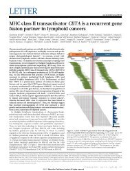
The i-LIMB Hand is the first commercially available multi-articulating bionic hand. Since it has<br />
five independently powered digits, many different grips can be achieved (key grip, power grip,<br />
precision grip, and index point). The precision grip is shown in Figure 4.1.3. The i-LIMB Hand<br />
and patient interact in a symbiotic way. The hand is controlled by sensing electrical impulses in<br />
the forearm, and is powered by internal batteries. The batteries drive the five motors for a<br />
complete day and recharge overnight. Cosmesis is a covering for the i-LIMB Hand that provides<br />
a more realistic appearance and protects the internal mechanisms. This device costs two to three<br />
times more than traditional myoelectric devices. The product is robust, is made from extremely<br />
strong plastics, yet it cannot be exposed to water.<br />
Fig. 4.1.3 <strong>–</strong> Touch Bionics: The i-LIMB System<br />
TRS’s Adult Grip Prehensors are high performance hand replacements. The 1/2 inch diameter<br />
threaded stud will attach to any U.S. made wrist unit. They are high in strength, constructed<br />
reliably, and require low maintenance. The Adult Grip Prehensors are body powered and are to<br />
9
e used with a harness. The website claims that the Grip Prehensors are the highest efficiency of<br />
any body powered prosthetic device available. Applications range from peeling a banana and<br />
slicing a tomato to using a wrench or hammer, weightlifting, or shooting a bow. The range of<br />
gripping force can exceed 100 pounds. The models are stainless steel with titanium side plates<br />
and polyurethane gripping surfaces as options. A few applications along with material choices<br />
appear in Fig. 4.1.4 below.<br />
Fig. 4.1.4 <strong>–</strong> TRS Adult Grip Prehensors and Sample Applications<br />
Liberating Technologies, Inc. markets a device known as the RSL Steeper MultiControl Plus<br />
prosthetic hand system. These hands can close in as little as 0.9 seconds and come in a variety of<br />
sizes. The RSL Steeper MultiControl Plus Hand has a new power management system called<br />
Power<strong>Force</strong>. This electronic circuit provides additional grip force on demand and acts like an<br />
electric automatic transmission. An image of this product can be seen below in Fig. 4.1.5.<br />
Fig. 4.1.5 <strong>–</strong> Liberating Technologies, Inc. RSL Steeper MultiControl Plus<br />
Motion Control Inc. provides an electronic prosthetic arm for above elbow amputations. Known<br />
as the Utah <strong>Arm</strong>, motion control released the third version in 2004. In this particular version,<br />
microprocessors were incorporated into the arm to allow wearers to make fine-tune adjustments<br />
to the movement of the arm. This particular arm provides proportional control which allows the<br />
wearer to move the arm and hand slowly or quickly in any position. The Utah <strong>Arm</strong> 3 can be<br />
found below in Fig. 4.1.6.<br />
10
Fig. 4.1.6 <strong>–</strong> Utah <strong>Arm</strong> 3<br />
MAGNUM Parallel Grippers are used in the robotics industry. They utilize third-generation<br />
Zaytran technology and are made of tough, corrosive resistant materials. The MAGNUM<br />
parallel grippers are used in a variety of environments from welding, grinding, machining, clean<br />
room, disk fabrication, and food processing. The force to weight ratio of these grippers is in<br />
excess of 200. The gripper consists of two independent systems; force and synchronizing double<br />
helix. The MAGNUM Parallel Gripper mechanism is double sealed to ensure isolation from the<br />
environment. In harsh environments the double seals protect the parallel gripper from<br />
contamination that could lead to failure. The MAGNUM Parallel Grippers are shown in use in<br />
Fig. 4.1.7.<br />
Figure 4.1.7<strong>–</strong> Zaytran: MAGNUM Parallel Grippers<br />
A vector is described by its magnitude and direction. Vector prehensors (Fig. 4.1.8) yield a<br />
variable gripping force by varying the direction of the rubber band closing force yet keeping its<br />
magnitude constant. When the rubber band angle is 90 degrees, grip force is maximized. As the<br />
band angle decreases, the torque applied by the band about the pivot decreases. Currently, the<br />
best design to date uses elastomer bands will last for more than 70,000 cycles at the highest grip<br />
force setting. Bands are contained within the casing to shield the elements. With the current<br />
design, the elastomer bands can be replaced by an individual with Phillips’ head and flathead<br />
screwdrivers in about 10 minutes. At the highest setting, grip force begins at about 11 lbs and<br />
gradually rises to nearly 20 lbs as the hooks are opened. There are 11 intermediate settings that<br />
provide a choice of grip force levels between these two extremes.<br />
11
Figure 4.1.8- Vector Hook and Vector Grip<br />
Custom <strong>Prosthetic</strong> Services LTD. offers a conventional body-powered prosthesis that works by<br />
means of the operator’s body to overcome the closing force of the terminal device. (Fig 4.1.9)<br />
The system works by the user shrugging his or her shoulder. This movement is intern captured<br />
by the butterfly back harness system (Fig 4.1.10), which is attached to a cable that runs down the<br />
arm and is connected to the terminal device.<br />
Figure 4.1.9 <strong>–</strong> Custom <strong>Prosthetic</strong><br />
Services Body-Powered Upper<br />
Extremity <strong>Prosthetic</strong><br />
Figure 4.1.10 <strong>–</strong> Body-Powered <strong>Prosthetic</strong><br />
Butterfly Harness<br />
Some advantages of this system is that it is highly durable, useful in wet, dirty or dusty<br />
environments, reduced maintenance cost compared to electrically driven prostheses, and is<br />
relatively simple. Yet, some drawbacks include that the user have a sufficient residual limb<br />
length, musculature, range of motion, and the overall prosthesis is not cosmetically pleasing due<br />
to exposed cables and hooks.<br />
12
Feature<br />
Hosmer Model 7<br />
Work Hook<br />
Otto Bock Vector<br />
Hook 10A60<br />
Touch Bionics: i-<br />
LIMB System<br />
TRS Adult Grip<br />
Prehensors<br />
RSL Steeper<br />
MultiControl<br />
Plus<br />
MAGNUM<br />
Parallel Grippers<br />
Vector Hook &<br />
Vector Grip<br />
Adjustable No Yes Uncertain Yes No Uncertain Yes<br />
Electronics No No Yes No Yes Yes No<br />
Power Source Body Powered Body Powered Batteries Body Powered Batteries Batteries Body Powered<br />
Cost ~$350 ~$400 +$1000 ~$400 ~$600 ~$300 ~$400<br />
Serviceability Yes Yes No Yes No Uncertain Yes<br />
Corrosion<br />
Resistant<br />
Reduces Input<br />
<strong>Force</strong><br />
Table 4.1.1 <strong>–</strong> Terminal Device Product Benchmarking<br />
Yes Yes Yes/No Yes No Yes Yes<br />
No Yes Yes Yes/No Yes Yes Yes<br />
Table 4.1.2 <strong>–</strong> <strong>Prosthetic</strong> <strong>Arm</strong> Product Benchmarking<br />
Feature Utah <strong>Arm</strong> 3<br />
CPS Body-<br />
Powered<br />
<strong>Prosthetic</strong><br />
Adjustable Yes Yes/No<br />
Electronics Yes No<br />
Power Source Batteries Body Powered<br />
Cost N/a ~$5,000<br />
Serviceability No Yes<br />
Corrosion<br />
Resistant<br />
Reduces Input<br />
<strong>Force</strong><br />
Yes Yes<br />
Yes No<br />
Through benchmarking, it has been determined that there is a diverse market of terminal devices<br />
as well as compatible substitutes. Further up the arm, the user has fewer options to choose from.<br />
In order to aid in concept generation and the overall project’s scope one must consider the<br />
customer’s needs as seen in section 2.0.<br />
The Hosmer Hook is a tried and true classic terminal device made specifically for agricultural<br />
purposes. It does not require any electrical components, it is affordable, serviceable, and is<br />
corrosion resistant. One of its major drawbacks is that there is no force adjustability and it would<br />
require modifications in order to use springs as the resistive force rather than its standard rubber<br />
bands. The Otto Bock Vector Hook 10A60 shares the same strengths as the Hosmer model but<br />
the user can adjust the force and therefore reduce to input needed to open the hooks. Also,<br />
springs come standard on the Vector Hook model.<br />
13
The i-LIMB Hand has taken years to develop and the overall level of detail is out of our scope.<br />
The myoelectric power and five independent motors are a little too advanced for this project, and<br />
the battery power it utilizes is something that we may not want to incorporate into our final<br />
design. The TRS Adult Grip Prehensor is very durable, so we may be able to incorporate its<br />
strength and simplicity of design components into our final design.<br />
The RSL Steeper MultiControl Plus is not sturdy enough for an agricultural environment, yet<br />
does have a convenient feature which is a quick closing time and automated power system. The<br />
MAGNUM Parallel Grippers utilize a veritable design with a great strength to weight ratio that<br />
could be used to aid us in final concept selection, but it would require an electrical power source<br />
in order to operate. The Vector Prehensors are very useful because the gripper force is<br />
adjustable. This is good for the farmers to use high grip force when using heavy duty jobs then<br />
lower the force for tasks that require less force.<br />
The two prosthetic forearms presented in this section (as seen in Table 4.1.2) represent the two<br />
major types of prosthetic arms. The Utah <strong>Arm</strong> 3 is a typical electric powered microprocessor<br />
prosthetic arm, and the Custom <strong>Prosthetic</strong> Services Body-Powered Upper Extremity <strong>Prosthetic</strong> is<br />
the typical body-powered prosthetic arm. Due to its robustness, years of testing and field<br />
experience, and simplicity the body powered prosthetic might be the ideal path for our<br />
customer’s needs.<br />
The benchmarking has illuminated some strong points and weak points of products that are<br />
currently available. We will use some of the strengths and improve some of the weaknesses seen<br />
in the above products to make our design work with our need statement, customer input, and<br />
requirements. Durability, grip strength, and ease of use will be strong differentiators of our final<br />
design as compared to the benchmarked products.<br />
4.2 Applicable Patents<br />
The following are patents that may apply to the particular focus of our project:<br />
1. Loveless, J. H., "<strong>Prosthetic</strong> Load-Lift Hook Locking Mechanism," U. S. Patent 4,074,367,<br />
February 21, 1978.<br />
• Describes an electronically controlled pawl and ratchet system that would increase the<br />
grip strength and lifting capacity of a prosthetic arm. A ratchet wheel in the elbow of the<br />
arm is driven by a motor and pulley system located in the upper portion/shoulder of the<br />
arm. This system is used to clamp the gripping portion of the arm, located in the position<br />
of the hand. A nice system, however, it is fairly complicated and requires that the entire<br />
arm be prosthetic. There would be no use for this system in the case of an amputation at<br />
the elbow.<br />
2. Cooper, C. M., "Harness for Control of Upper Extremity Prosthesis," U. S. Patent 3,188,655,<br />
June 15, 1965.<br />
• Describes a harness that can be attached to a hook at the end of a prosthetic arm. By<br />
raising their opposite arm the user of this harness can open the hook at the end of<br />
their prosthetic arm. When the arm is lowered to the normal position the prosthetic<br />
14
hook is closed. The harness idea is one worth consideration but used in the manner<br />
shown here it is doubtful that the gripping force needed in our application could be<br />
achieved. A modification of this system could definitely be used in a future design.<br />
3. Threewit, D. M., "Terminal Connection for Control Cables," U. S. Patent 2,493,841, January<br />
10, 1950.<br />
• Describes a means for attaching and operating a cable in order to open and close a<br />
hook attached at the end of a prosthetic arm. A modification of this patent could be<br />
used in conjunction with the above harness.<br />
4. Radocy, R. and Dick, E., "<strong>Prosthetic</strong> Terminal Device," U. S. Patent 4,225,983, October 7,<br />
1980.<br />
• Describes a claw that is to imitate the gripping action of the thumb and forefinger.<br />
The device is closed through the use of an attached cable and is spring-loaded to<br />
return to the open position. The device utilizes two manual locking devices and three<br />
gripping surfaces to provide a variety of closed positions that allow for the grasping<br />
of objects of different sizes.<br />
5. Landsberger, S. L., "Artificial Hand For Grasping an Object," U. S. Patent 7,087,092,<br />
August 8, 2006.<br />
• Describes an alternative gripping device that utilizes two “fingers” which are<br />
connected to a “thumb.” This device resembles the human hand except in uses three<br />
“fingers” instead of five.<br />
6. Farquharson, R. H. and Still, D. P., "Attachment for Artificial <strong>Arm</strong> <strong>Prosthetic</strong> Device," U. S.<br />
Patent 5,464,444, November 7, 1995.<br />
• Describes a terminal device comprises of a first main part in operable and pivotal<br />
combination with a second main part, the combined main parts providing on one end<br />
a device for attaching to the end of an arm prosthesis, and on the other a device for<br />
attaching a variety of implements, the said device for implement attachment<br />
providing articulation capabilities that allow positioning of the implements in a<br />
variety of positions relative to the position of the arm prosthesis.<br />
7. Zajac, T. S., “Device for Gripping Workpieces,” U.S. Patent 4,591,199, May 27, 1986.<br />
• Describes a device for which fluid pressure is applied to opposite pistons connected<br />
to a gripping jaw hence moving the jaws open and closed. A rod extending along the<br />
axis of the two cylinders which is interconnected to the pistons is the means for<br />
synchronous movement. The interconnection affects rotation of the rod in opposite<br />
directions upon movement of the pistons with a bearing assembly located between the<br />
two fluid cylinders supporting the rod for rotation. The MAGNUM Parallel Grippers<br />
(Fig. 4.1.7) utilize this patent.<br />
4.3 Applicable Standards<br />
There are Quality Standards set for suppliers of Durable Medical Equipment, <strong>Prosthetic</strong>s,<br />
Orthotics, and Supplies (DMEPOS). The organization recommends that the supplier of a custom<br />
fabricated, custom fitted, custom-made prosthetic device be trained in a wide variety of treatment<br />
15
options. The definition given for a prosthetic device is any device (other than dental) that<br />
replaces all or part of an internal body organ (including contiguous tissue), or replace all or part<br />
of the function of a permanently inoperative or malfunctioning internal body organ.<br />
The prosthetic device must be in accordance with Medicare contractor policies (if applicable to<br />
user). The supplier shall perform a diagnosis-specific clinical examination and access and<br />
understand manufacturer guidelines prior to fitting. There should be an implementation plan also<br />
should be consistent with the prescribing physician’s written plan of care. Appropriate<br />
beneficiary follow-up care consistent with the items or service(s) provided, the beneficiary’s<br />
diagnosis, specific care rendered should be provided. The beneficiary or caregiver should be<br />
informed of the procedures for repairing, replacing, and/or adjusting the device or items.<br />
The caregiver should review care and maintenance instructions and provide necessary supplies<br />
(e.g. adhesives, solvents, lubricants) to attach, maintain, and clean the items, as applicable, and<br />
provide information about how to subsequently obtain necessary supplies. Also inspection and<br />
monitoring should be done for potential complications.<br />
Though these standards are more applicable to a supplier of the prosthetic device, not so much<br />
the designer, useful information could still be applied to our project. One important<br />
consideration is to fully educate the user on how the prosthetic works, inform them of any<br />
potential hazards or limitations of the device, and verify the compliance with the customer’s<br />
current prosthetic. If any questions arise, a medical professional will be a great source of further<br />
detail in each specific case. In the context of our design it is important that the end user be<br />
properly and thoroughly trained in how to operate the system before using it as well as informed<br />
of the procedures for repairing, replacing, and/or adjusting the device.<br />
4.4 Applicable Constraints<br />
Internal constraints include beginner level engineering experience, a limited budget, and a time<br />
constraint for development. The skill level of the team is entry-level with respect to engineering<br />
abilities meaning not all our decisions would be similar to decisions that would be made by<br />
seasoned prosthetic engineers given the same design circumstances. We will make the best<br />
decisions and choices with our knowledge, background research, and feedback received from<br />
professionals and customers.<br />
The construction of the product will be professional, yet will not be on the same level as a fullscale<br />
manufacturing plant since budget is limited, commodity prices are on the rise, and our<br />
manufacturing facilities are a bit small and limited. Compromise, value engineering, and advice<br />
from professionals will be utilized to help make smart decisions. Too much redesigning will not<br />
be possible on a limited budget or schedule. This will be accounted for by planning and<br />
developing concepts early and often before our final design criteria is selected. The overall<br />
product will reflect our high quality operation and level of thought and will help consumers with<br />
upper extremity loss succeed in the field of agriculture.<br />
There is an external constraint to our project which would be the limited market. A person with<br />
upper extremity loss and who would like to peruse and prosper in the agricultural field would fit<br />
our needs area. They must also have knowledge of our product and have adequate resources to<br />
16
purchase it. Safety is another external constraint. The device must be safe which means an<br />
ability to be released quickly so that secondary injuries do not occur in an emergency situation.<br />
Standards, previous patents, and pre-existing products will guide our final design, yet with<br />
creativity and ingenuity, our product will be significantly differentiable and salable to fit the<br />
target market and help people with upper extremity loss work in agriculture.<br />
5.0 Concept Generation<br />
The typical approach to generating concepts used by this team has been to brainstorm<br />
individually and then relay any ideas at the weekly meeting. During these meetings each concept<br />
is critiqued by all members of the group and the team is able to build off ideas submitted by<br />
other individuals in the group.<br />
The Bureau of Vocational Rehabilitation (BVR) and their engineers have provided meaningful<br />
feedback regarding concepts developed by the group. Additional customer input was added<br />
during the conceptual generation phase. The National AgrAbility Project is concerned with<br />
assisting disabled farmers and ranchers. Mark Novak is involved with the project and relayed<br />
areas in agriculture where disabled farmers are seeking assistance. He was also able to link<br />
information related to projects that have already been completed by engineering design groups at<br />
the <strong>University</strong> of Wisconsin - Madison. Through the BVR direct customer contact was achieved<br />
with Tim Lang, a dairy farmer in Marietta who has a complete arm prosthetic on his right arm.<br />
Tim has also been instrumental in providing sound feedback on concepts as well as providing<br />
ideas of his own.<br />
The feasibility of each of the concepts is our main concentration. If the idea is not feasible, and<br />
has no real-world expectations or usages, then there would be no reason to move forward with<br />
the design aspect of the idea. Once a concept has been deemed feasible it can be allowed to<br />
progress in the design process.<br />
Initial feedback from Tim Lang resulted in several areas of concentration for the design of a<br />
system that could benefit him in his everyday activities. To address these areas the following<br />
concepts were deemed feasible:<br />
A) Fabricating a hook of our own design that incorporates a vector hook system to allow<br />
flexibility in grip strength and opening force required.<br />
B) Using the Otto Bock Model 10A60’s current vector system to produce flexibility in grip<br />
strength and thus opening force required.<br />
C) Creating a mechanical advantage system to mount inside of the prosthetic forearm in order<br />
to reduce the opening force required from the user.<br />
D) Upgrading the springs used by the Otto Bock Model 10A60 to a stronger version that would<br />
increase the grip strength of the hook.<br />
5.1 Concept Generation<br />
Initial brainstorming for conceptual design began in class with discussion regarding possible<br />
routes that could be taken to solve our refined need statement. After each discussion each person<br />
17
was given a few days to come up with some conceptual designs of their own. Once properly<br />
prepared, we would meet once more as a whole and discuss different alternatives that each<br />
member had thought of with regard to our project idea(s). This practice has been the most<br />
effective process that our group has used to generate alternative concepts. These concepts were<br />
drawn on a board in front of all members and discussion was given to each idea. No concept was<br />
thrown out, but instead the pros and cons of each device were debated so that each member<br />
might be able to come up with ideas for improvement or new ideas all together. Sketching and<br />
solid edge modeling of these concepts are shown below.<br />
5.1.1 Concept A <strong>–</strong> Fabricated Hook<br />
Figure 5.1.1 <strong>–</strong> Sketch of Initial Hook Concept<br />
The initial concept of a hook to be fabricated is shown in Figure 5.1.1. This hook utilized a<br />
vector system by allowing the “screw adjustment” on the left side of the drawing to side between<br />
the upper position and lower position, symbolized by the arrow in the drawing. An additional<br />
feature of this first design was the implementation of an adjustable grip width by utilizing a<br />
movable jaw. The dashed line in the bottom right of the drawing shows the “cart” that the<br />
movable jaw would have moved through in order to accomplish this feature. Future contact with<br />
Tim Lang cited that this feature was not needed and would have been a waste of resources.<br />
18
Figure 5.1.2 <strong>–</strong> Solid Edge Model of Refined Hook Concept<br />
Shown above is the second iteration of the hook concept. The movable jaw feature has been<br />
eliminated from this design and a different approach to the vector system has been implemented.<br />
Rather than use a “screw” to adjust the vector position of the hook, the body of the book has<br />
been drilled out in three places to allow for three potential locations of spring placement. The<br />
lever on the left side of the hook can be pulled outward and then slid and released into the<br />
appropriate location.<br />
5.1.2 Concept B <strong>–</strong> Otto Bock Model 10A60 Vector Hook<br />
During the design of our own vector hook system it was discovered that there was a pre-existing<br />
hook of very similar operation. The Otto Bock Model 10A60 shown below incorporates and 2setting<br />
vector system.<br />
Figure 5.1.3 <strong>–</strong> Otto Bock Model 10A60 Vector Hook<br />
19
As can be seen in Figure 5.1.3 the Otto Bock hook allows the user to select an approximately<br />
half force setting by placing the lever in the location shown in the photo. By flipping the lever to<br />
the left (with respect to the fig.) the springs are placed in the full force orientation. Inspection of<br />
Figure 5.1.2 and Figure 5.1.3 shows that both our concept and the existing Otto Bock design are<br />
very similar.<br />
5.1.3 Concept C <strong>–</strong> Mechanical Advantage System Located in Forearm <strong>Prosthetic</strong><br />
The concept of a mechanical advantage system was developed in order to further reduce the user<br />
input required by the customer. The decision was made to implement the system inside of the<br />
hollow prosthetic forearm system. It was deemed a safety hazard to try and incorporate any type<br />
of similar concept on the exterior of the forearm as it could easily be snagged on many of the<br />
rapidly moving parts encountered by a farmer in his day-to-day work. Below, Figure 5.1.4<br />
displays how a 2:1 mechanical advantage could be achieved.<br />
Figure 5.1.4 <strong>–</strong> Mechanical Advantage Concept<br />
This concept incorporates the use of a pulley to achieve the mechanical advantage. The cable<br />
attached to the user’s harness would wrap around the pulley and anchor inside of the arm. A<br />
separate cable would then travel from the pulley to the user’s hook. The rings shown at either<br />
extremity of the drawing would mount to the interior walls of the forearm. Figure 5.1.5 shows<br />
the design incorporated inside of the forearm with the Otto Bock hook attached.<br />
Figure 5.1.5 <strong>–</strong> Mechanical Advantage System Concept Inside Forearm<br />
20
5.1.4 Concept D <strong>–</strong> Upgraded Springs for the Otto Bock Hook<br />
Once the similarities between our concept and the existing Otto Bock hook were noted, the team<br />
was fairly adamant about sourcing an Otto Bock hook rather than fabricate our own design. The<br />
Otto Bock hook incorporates four springs total <strong>–</strong> two springs on either side of the hook with one<br />
spring encompassing the other on either side of the hook (see Figure 5.1.3). In order to increase<br />
the grip force of this hook, more rugged springs could be incorporated. Figure 5.1.6 shows what<br />
the Otto Bock hook might look like with a stronger spring incorporated on one side of the hook.<br />
Figure 5.1.6 <strong>–</strong> Otto Bock hook with Upgraded Spring<br />
5.2 Concept Development, Scoring and Selection<br />
Table 5.2.1 (as seen on the next page) was used in order to select which of the four concepts<br />
should be pursued. It was decided by the team that our resources could be allocated effectively<br />
to develop 2-3 of the concepts that were discussed. Two sets of criteria were used in determining<br />
the best concepts <strong>–</strong> “user needs” and “producer” criteria. Various aspects of these categories<br />
were the broken down and rated with what we deemed an “importance factor.” Each concept<br />
was then objectively rated in each of these areas and the value given to each concept was<br />
multiplied by the importance factor. In order to determine the best concepts all that had to be<br />
done was sum the total ratings of each individual concept. Ultimately the decision was made to<br />
progress with the two highest rated concepts.<br />
21
User Need Criteria<br />
Producer<br />
Criteria<br />
Concept<br />
Table 5.2.1 <strong>–</strong> Concept Scoring<br />
Fabricated<br />
Hook<br />
Otto Bock<br />
Model 10A60<br />
Mechanical Adv.<br />
System<br />
User Need Criteria Standards:<br />
1) Reduced User Input <strong>–</strong> Does this concept have the potential to provide a significant<br />
reduction in user input force required?<br />
2) Increased Grip Strength <strong>–</strong> Does this concept have the potential to provide an increase<br />
in grip strength over Tim’s current hook?<br />
3) Serviceable <strong>–</strong> Could this concept be serviced by the user without the assistance of a<br />
professional?<br />
4) Reliable <strong>–</strong> Will this product function correctly without regular maintenance so as not<br />
to reduce the users’ productivity?<br />
5) Corrosion Resistant <strong>–</strong> Can this concept be made out of materials that can withstand<br />
the agricultural environment?<br />
6) Affordable <strong>–</strong> Will this concept provide enough value to the customer that they can<br />
justify the cost?<br />
7) Simplicity of Use <strong>–</strong> Will this concept be as easy to use as the customer’s current<br />
application?<br />
8) Light Weight <strong>–</strong> Will this concept be light enough so as not to discomfort the user with<br />
added weight at the wrist or forearm?<br />
UProducer Criteria:<br />
1) Easily Manufactured <strong>–</strong> Does this team, as the producer of the product, have the skills<br />
and tools necessary to create and build all parts?<br />
2) Affordable <strong>–</strong> Can this product be made cheap enough that it can be sold at a profit and<br />
still provide significant value to the customer?<br />
3) Marketable <strong>–</strong> Would this concept provide a feature that would interest customers?<br />
4) Original <strong>–</strong> Does this concept provide a feature that is either new or vastly improved<br />
over current products in the market?<br />
Otto Bock<br />
Spring Upgrades<br />
Importance<br />
Factor (0-1)<br />
Rating [( 1-exceeds spec, 0-does not meet spec)*imp. factor]<br />
Reduced User Input 1.0 0.70 0.70 0.90 0.00<br />
Increased Grip Strength 1.0 0.50 0.60 0.00 0.90<br />
Serviceable 0.9 0.36 0.72 0.72 0.63<br />
Reliable 0.9 0.36 0.72 0.63 0.54<br />
Corrosion Resistant 0.8 0.64 0.64 0.64 0.48<br />
Affordable 0.6 0.18 0.42 0.54 0.42<br />
Simplicity of Use 0.5 0.25 0.45 0.40 0.35<br />
Light Weight 0.4 0.20 0.28 0.28 0.32<br />
Easily Manufactured 0.9 0.09 0.90 0.63 0.90<br />
Affordable 0.8 0.24 0.40 0.72 0.40<br />
Marketable 0.8 0.16 0.64 0.40 0.48<br />
Original 0.5 0.40 0.25 0.40 0.25<br />
TOTAL 4.1 6.7 6.3 5.7<br />
Relevance (1-highest, 4-lowest) 4 1 2 3<br />
22
6.0 Concept Selection<br />
6.1 Data and Calculations for Feasibility and Effectiveness Analysis<br />
6.1.1 - Static Analysis of Split-Hook Gripping <strong>Force</strong> and Necessary User Input<br />
Two of our proposed designs resemble traditional prosthetic terminal devices. Two of the most<br />
important parameters of a gripping device are the gripping force it provides, and the force needed<br />
to open it. The following analyses are configured to resemble a classic “split hook” design.<br />
Figure 6.1.1 <strong>–</strong> Classic Split Hook Design<br />
This design uses two hooks, one is mobile (upper hook in picture), and one is fixed (lower hook).<br />
The hooks are held together by a series of rubber bands. The user opens the hook by applying a<br />
force to the cable (seen at the right side of the picture). The amount of rubber bands, and the<br />
nature of the “cable post” are two things that can alter the gripping force, and the amount of user<br />
input needed to open the mobile hook. The following analyses utilize simple static models to<br />
formulaically simulate this design.<br />
UDetermining Gripping <strong>Force</strong>U:<br />
Figure 6.1.2 shows a simple static model of the moveable hook on a split hook prosthetic<br />
terminal device.<br />
Fr = Spring or rubber band force Fg = Gripping force<br />
Dr = Rubber Band Distance from Pivot L = Overall length of hook<br />
Figure 6.1.2 <strong>–</strong> Static Model of Moveable Hook<br />
23
Using simple static analysis, the resulting grip force (Fg) can be calculated by summing the<br />
moments about the pivot point on the right side:<br />
The term “Fr” in these equations is equal to k*xo (via Hooke’s Law), where “xo” is the<br />
elongation of the rubber band at the closed position of the hooks.<br />
UDetermining Needed User InputU:<br />
Figure 6.1.3 shows “top-down” views of the mobile hook in the closed (left) and partly open<br />
(right) positions<br />
Fr = <strong>Force</strong> of rubber band Dr = Distance from rubber band to pivot<br />
Fc = Cable force supplied by user (constant) Dp = length of cable post<br />
Figure 6.1.3 <strong>–</strong> Top-Down FBD<br />
“Fc” is considered a constant for this section, and it is assumed that the user is applying<br />
maximum force throughout the entire opening range of the hook. It is also assumed that the<br />
hook runs through a guide before it connects to the post on the hook. This keeps the user force<br />
vector in one direction at all times. Since torque is what we are after for this section, the forces<br />
“Fr” and “Fc” have to be resolved, so they are perpendicular with “Dr” and “Dp”, respectively.<br />
Figure 6.1.4 (as seen on the next page) shows the components needed to resolve the user input<br />
force (Fc).<br />
(2)<br />
(3)<br />
(4)<br />
24
Figure 6.1.4 <strong>–</strong> Input <strong>Force</strong> FBD<br />
The interior angle between Fc and Fc’ is equal to Ѳ. Therefore, both the resolved force, and<br />
subsequent torque can be determined easily:<br />
(user induced torque)<br />
Figure 6.1.5 shows the components necessary to resolve the force due to the rubber band.<br />
Figure 6.1.5 <strong>–</strong>Rubber Band FBD<br />
Please note that the rubber band force (Fr) will increase as a function increasing Ѳ. Therefore,<br />
Fr must be defined functionally:<br />
For this equation, “Fro” is equal to the rubber band force at Ѳ =0 (which is equivalent to the “Fr”<br />
from Figure 6.1.1). Also, “x” is equal to the amount of additional elongation the rubber band<br />
(5)<br />
(6)<br />
(7)<br />
(8)<br />
25
experiences for any Ѳ greater than 0. The interior angle between “Fr” and “Fr’” is equal to Ѳ.<br />
The resolved rubber band force (Fr’) can then be solved similar to the resolved user input force:<br />
Figure 5 illustrates the way that the term “x” is also a function of Ѳ.<br />
Figure 6.1.6 <strong>–</strong> Displacement & Angle FBD<br />
Combining these two functions, the resolved rubber band force and the resulting rubber bandinduced<br />
torque can be determined:<br />
Figure 6 shows the hook drawing with both forces resolved.<br />
Figure 6.1.7 <strong>–</strong>Resolved <strong>Force</strong>s FBD<br />
(9)<br />
(10)<br />
(11)<br />
(12)<br />
26
Since the torques of the both the rubber band (Tr) and the User (Tc) can be determined easily by<br />
using Figure 6, the following fraction can be utilized to monitor the user’s capability to open the<br />
hook.<br />
(Capability Index)<br />
By plotting the Capability Index for the hook’s entire range of angular motion, the relative ease<br />
which the user will experience while opening the hook (assuming they apply full force for the<br />
entire travel of the hook) can be observed. This is shown in Figure 6.1.8.<br />
The plot labeled “GOOD” indicates that the user is capable of opening the hook throughout its<br />
entire range of motion. The ease of opening, however, diminishes as the springs/rubber bands<br />
are stretched increasingly. The plot labeled “BAD” shows that at some intermediate Ѳ, the<br />
torque input from the user becomes equivalent to the torque produced by the stretched<br />
springs/rubber bands. Since the user’s input force is assumed to be maximum, the user is not<br />
capable of opening the hooks beyond this point.<br />
UDetermining Minimum Opening <strong>Force</strong>:<br />
Figure 6.1.8 <strong>–</strong> Capability Index Plots<br />
It may also be of interest to find what minimum amount of user force (Fcm) is needed to open<br />
the hooks to some angle Ѳ. This can be done easily, using the equations derived from the prior<br />
sections.<br />
(13)<br />
(14)<br />
(15)<br />
(16)<br />
27
6.1.2 - Analysis of Pulley Based Mechanical Advantage<br />
Figure 6.1.9 <strong>–</strong> Mechanical Advantage by the Use of a Pulley<br />
Using basic physics, a pulley can be used to theoretically cut the input force needed to move an<br />
object in half. When a pulley is not used, the input force is equivalent to the output force.<br />
Likewise, when a pulley is being used as shown in Figure 6.1.9, the tension in the cable around<br />
the pulley is the same. In the system used for this project, the “W” would be the hook post. The<br />
“W/2” on the right side is the grounded cable and the “W/2” on the left side is the cable that<br />
connects to the customer’s back harness.<br />
A disadvantage to the pulley system is the work required still remains the same.<br />
Work = force * distance<br />
Since the force is cut in half, the distance required is twice as much as when the pulley wasn’t<br />
used. This trade off of cutting the input force in half but doubling the necessary cable travel<br />
could be an issue in our finalized design.<br />
6.2 Concept Screening, Development and Selection<br />
Through our interaction with Tim, he stated that he wished for more grip force out of his current<br />
prosthetic, but also cited pain in his back and shoulders after a long days work with his current<br />
prosthetic’s grip force. Realizing that this was a major issue to Tim, we began discussing ways to<br />
address this problem. We very quickly realized that a mechanical advantage system was most<br />
likely the only way that our group would be able to achieve this feat. The system would allow<br />
for reduced stress on his body due to the input force being cut in half, therefore allowing for the<br />
possibility of a higher grip strength. After speaking with Tim and explaining the concept of the<br />
mechanical advantage system, he seemed very eager to see what our design had in store for him,<br />
as well as to test the input force required to open the hook. Therefore, we began focusing on,<br />
and designing a mechanical advantage system to fit within Tim’s forearm.<br />
(17)<br />
(18)<br />
28
Once the design of the system was underway, we realized that it would be nearly impossible to<br />
design the system to fit within Tim’s current forearm without numerous problems. Also, we<br />
would not be able to remove his forearm due to him needing it in his everyday life. Therefore<br />
our next step of the project was to find and order a forearm very similar to Tim’s so that we<br />
could put our system within that forearm instead.<br />
Our group met with Tim numerous times throughout the designing and manufacturing processes,<br />
where we took numerous measurements of Tim’s current forearm, cable travel, wall thickness,<br />
etc. enabling us to properly order a similar forearm from a prosthetic manufacturer. Tim pointed<br />
us in the direction of Yankee Bionics, a prosthetic manufacturing company in Akron, <strong>Ohio</strong> that<br />
he worked with in the manufacturing of his current prosthetic device. The company was nice<br />
enough to donate a slightly used forearm for the use in assisting Tim. Once we received the<br />
forearm, we finalized all of the necessary measurements and began manufacturing the<br />
mechanical advantage system, and completed the installation. Once our system was bolted<br />
within the forearm, the cable travel was then established. A small hole was then drilled through<br />
the exterior wall of the forearm, allowing the cable to be attached to the hook.<br />
Once the manufacturing was completed, the only step left in our project was to let Tim test the<br />
overall system and see how it performed. Where, after visiting Tim and allowing him to test the<br />
system, he was overwhelmed with how much easier our system was to open than his original<br />
prosthetic.<br />
7.0 Final Design<br />
7.0.1 Introduction<br />
A prosthetic arm force reducer was manufactured by designing a pulley mechanical advantage<br />
system housed within the hollow forearm section of the prosthetic with a 10A60 Otto Bock<br />
prosthetic terminal device.<br />
This design emerged after extensive interaction with customers, primarily Tim Lang, who<br />
precisely met the demographic we specified at the beginning of the project. Not only did this<br />
interaction help us to identify legitimate customer needs and eliminate unnecessary design<br />
features, but it also allowed us to take real measurements, which we used to confidently refine<br />
the newly-emergent subsystems.<br />
Through application of DFMA design principles, we have designed the mechanical advantage<br />
system to meet customer expectations, be readily manufactured, easily installed, minimally<br />
intrusive, and reasonably simple to analyze. This section concerns the implications of our design<br />
decisions.<br />
7.0.2 Impacts/Effects<br />
The first major impact concerns the choice of hook that we are using. The customer’s current<br />
hook utilizes rubber bands to supply the closing force of the hook. As a result, the customer has<br />
resorted to attaching a large number of rubber bands in order to achieve the grip strength that can<br />
be accomplished by using the springs available with the Otto Bock Model A60. The two-load<br />
29
hook allows the customer to operate in the full strength position only when necessary. Customer<br />
interaction has confirmed that this full strength setting offers more grip force than his currently<br />
modified prosthetic. Additionally, the customer can use half of the grip force and, therefore,<br />
have only half of the input force by a simple adjustment of a lever. Immediate effects of the<br />
upgrade to springs are that the user will be able to perform a wider variety of tasks with the<br />
increased grip force and also use the hook at half power, similar to a standard existing one-load<br />
hook. Long term effects could include fatigue and increased stress on the user’s body if the hook<br />
is used at full load fairly often and possibly an increase in the stresses in the entire prosthetic<br />
resulting in shorter product life due to fatigue.<br />
The mechanical advantage system offers relief for this. The ideal case for this system would<br />
give the user a 2:1 advantage in the input force required to open the spring hook. For example:<br />
Assume the original spring at the high setting required 35 lbs. Now, with the mechanical<br />
advantage pulley, it should ideally only require 17.5 lbs to open the hook at full load. The<br />
impact of this system to the user would be a drastic reduction of the input force required for both<br />
settings on the two-load hook. Our design reduces the input force required by the user by 47%<br />
from 18 lbs to 9.5 lbs or about a 1.9:1 advantage.<br />
The negative impacts discussed for the move to the Otto Bock hook and its stiffer springs would<br />
be reduced significantly, because even with an increase in grip force, the user would be able to<br />
exert less force than in an unmodified system. With respect to the mechanical advantage system,<br />
the user would theoretically have to pull their cable twice as far as was previously required to<br />
fully open the hook in order to balance the energy and forces for a 2:1 mechanical advantage. It<br />
currently takes about 1.75 inches of cable travel to fully open the customer’s hook. The Otto<br />
Bock hook, however, does not open as wide as the customer’s hook. This reduces functionality<br />
somewhat, but is beneficial in that he will only have to pull the cable ~2.75” inches, instead of<br />
the 3.5 inches it would take to fully open his current hook.<br />
Short term effects of a mechanical advantage system upgrade would be an increase in user<br />
comfort due to the ease in which he or she can use their prosthesis. It would allow for the<br />
immediate implementation of an increased-strength two-load hook without increasing the force<br />
needed to operate such a device.<br />
Long term effects are an increased life for the cable operating the pulley, and an increase in the<br />
workload the user could accomplish. Some possible negative long term effects could include<br />
shorter lifespan of the cable post and the cable connecting it to the pulley since they would be<br />
experiencing an increase in tension from the springs. Also, there is a possibility of eventual back<br />
and shoulder injuries from prolonged use, though this fact exists with all current prosthetic hook<br />
designs.<br />
The overall impact of the production of this system on the environment or society would not be<br />
very significant. As currently designed, this upgrade kit uses mostly pre-produced parts that<br />
need little machining. Most of the work required is in assembly and can be done by a few<br />
trained operators. The greatest impact or effect of the combined upgrade system would be to the<br />
life of the customer who would be using this system on a daily basis, allowing him or her wider<br />
range of tasks that they can complete and decreasing the wear on his or her body.<br />
30
7.0.3 Professional/Ethical Standards<br />
Our team’s main goal is to help our customer, Tim Lang. We believe that our decisions should<br />
benefit him, first and foremost, and also stay within our parameters with respect to safety of our<br />
team and customer, budget, and design specifications. Our team conducts our meetings in a<br />
professional and productive manner, and pays close attention to our schedule to maximize<br />
efficiency and overall benefit to Tim. This attitude is reflected in our decision making process,<br />
customer and team interaction, and devotion that each team member has to our goals and<br />
successful completion of our project. Also, working together as a cohesive unit is far more<br />
productive than acting as individual with disjointed priorities.<br />
7.0.4 Function<br />
In order to add mechanical advantage to our system, a movable pulley was mounted in the<br />
forearm of the prosthetic. A movable pulley allows the user to input only half of the force<br />
required to open the hook. This is due to the fact that the forces on the pulley have to balance<br />
when the pulley is at equilibrium. Since two ends of the input cable are supporting the pulley in<br />
one direction, they will equally share the load pulling on the axle of the pulley. In our case, the<br />
load on the pulley will be the force required to open the prosthetic hook. Therefore, our<br />
customer will be able to pull on the free end of the input cable with half of the force required to<br />
open the hook. In the ideal case this will be a 2:1 advantage. A small disadvantage to the system<br />
is that it requires twice the input cable travel in order to obtain the mechanical advantage. This<br />
has been talked over with the customer and has been deemed an acceptable trade-off for gaining<br />
a 2:1 advantage.<br />
7.0.5 FMEA & Safety<br />
Figure 7.0.1 <strong>–</strong> Mechanical Advantage Schematic<br />
For the hook, initial consideration was given to minimize ways in which the Otto Bock design<br />
may fail in the agricultural setting where it would be used. This was approached by completing<br />
FMEA of the hook design, and the results of this analysis are presented in table 7.0.1.<br />
31
Failure Mode<br />
Table 7.0.1 - Risk Priority Number Analysis for Split Hook (Environmental)<br />
Potential<br />
Severity<br />
Likelihood of<br />
Occurrence<br />
Probability of<br />
Detecting<br />
Cable Break (at fitting) 7 3 8 168<br />
Corrosion Over Time 2 10 5 100<br />
Threading of <strong>Prosthetic</strong><br />
Connection<br />
RPN<br />
6 2 6 72<br />
Environmental Deposits 2 10 1 20<br />
Loss of Movement of<br />
Vector Hook<br />
3 5 1 15<br />
These failure modes were listed in order of importance according to the risk priority number<br />
(RPN) calculated in the far right column. The RPN is the product of potential severity,<br />
likelihood of occurrence, and detect-ability of the particular failure mode, as ranked on a scale<br />
from one to ten.<br />
Since the Otto Bock hook has been left in stock, OEM condition, failures relating to the stresses<br />
present in the hook itself were not included. The mechanical advantage, however, does allow the<br />
user to hypothetically pull twice as hard on the hook at full opening. Although this situation is<br />
not practical, it could lead to failures in the hook, which is not designed to experience twice as<br />
much force as is needed to open it to its maximum width.<br />
Corrosion over time and the hook accumulating environmental deposits are completely<br />
unavoidable considering the working conditions that it will be used under. As such, a stainless<br />
steel hook has been selected and all fabricated parts shall be made of stainless steel.<br />
Additionally, any mud or other element that fills some part of the hook should be able to be<br />
easily removed by our user.<br />
The only other failure mode of the hook of much concern was if the threading of the hook could<br />
be stripped in some way. The prosthetic arm provides the biggest guard against anything<br />
happening to the threading as the hook threads into a bushing that is then inserted into the<br />
prosthetic arm. This ensures that the threading is not constantly under torque but instead the arm<br />
will bear this force.<br />
FMEA was also completed for the mechanical advantage portion of the design in the same<br />
manner as conducted for the environmental effects on the system. The FMEA results are<br />
presented below in table 7.0.2.<br />
32
Table 7.0.2 - Risk Priority Number Analysis for Mechanical Advantage<br />
Potential Severity Likelihood of Occurance Probability of Detecting RPN<br />
Threading of Rings Strips<br />
Resulting in System Pulling<br />
Away From <strong>Prosthetic</strong> Walls<br />
7 (Inoperable)<br />
3<br />
6<br />
168<br />
Pulley Torques in Track<br />
and Locks<br />
5 (Temp. Inoperable)<br />
4<br />
8<br />
160<br />
Rope Slips From Pulley<br />
Wheel<br />
5 (Temp. Inoperable)<br />
4<br />
8<br />
160<br />
Bearings Seize in Track 5 (Temp. Inoperable)<br />
4<br />
4<br />
80<br />
Tracks Break Attachment<br />
With Rings<br />
7 (Inoperable)<br />
1<br />
6<br />
42<br />
By comparing the RPN’s of the mechanical advantage system to the RPN’s of the environmental<br />
effects, the numbers are similar. At very worst, the user loses the ability to open or close the<br />
hook. At minimum, the faulty system would pose significant to the user.<br />
The worst failure with regard to mechanical advantage is if the rings that attach to the prosthetic<br />
were to strip and the bolts pull away. This would result in the system becoming completely<br />
inoperable and could cause damage to the prosthetic arm as well. This failure possibility is<br />
minimized by the fact that correct design of the threads can nearly eliminate that possibility. In<br />
addition, there would be the possibility of detecting the failure as the system should develop<br />
some amount of “slop” or looseness before it became completely separated from the prosthetic<br />
wall.<br />
The possibility of the pulley seizing in the track or the rope slipping off the pulley wheel is<br />
legitimate; however, such a failure would only leave the system temporarily inoperable. It would<br />
be a significant inconvenience for the user, but would not leave them in any real danger.<br />
If the bearings were to lock in the track it would leave the system inoperable but there should be<br />
only a very small chance of this occurring. Additionally this would more than likely occur due<br />
to build-up of some type of deposit in the track that could be removed to allow the system to<br />
operate once again. If the tracks were to break at the ring it would leave the system totally<br />
inoperable, but as with the bearings, once again there is a very small chance of occurring.<br />
7.0.6 Economics/Value<br />
The decision to fabricate the tracks for the mechanical advantage system out of square tubing<br />
was economical. Both the manufacturing time and price are significantly less for this design<br />
than it would be to fabricate the tracks out of solid stock. The options for buying tracks were<br />
around the same base cost as the square tubing we chose ($7.82 per 12” length), but the quality<br />
and material were not acceptable. The most common track was made out of extruded aluminum<br />
which could bend and deflect relatively easily and is not compatible for welding with stainless<br />
steel.<br />
33
The rings are the most expensive part of the mechanical advantage system because they will be<br />
made out of a 2-1/2” diam. stainless steel pipe. The minimum length of stock for this pipe size is<br />
12’’ and as such a large amount of extra material had to be purchased. The high cost<br />
(approximately $73) is hard to justify for the construction of a single system, however this stock<br />
would be fine if multiple systems were to be constructed.<br />
A nylon pulley with a stainless steel housing was selected. This item cost around $20 and will<br />
require no additional modifications. The bearings were selected due to the flexibility of sizes<br />
available and the low cost. Ball bearings are approximately one-third the cost of rubberized<br />
wheels. The 1/4” diameter stock for the axles and spacers was very inexpensive at around $6 per<br />
12” length. All materials, with the exception of the nylon pulley, of the mechanical advantage<br />
system are stainless steel which makes any necessary welding possible and is good for corrosion<br />
7.0.7 Design Analysis<br />
For mechanical advantage system, yielding of the tracks is the most pertinent failure mode for<br />
formal analysis. This failure mode involves potential yielding of the track’s sidewalls due to the<br />
forces inherent to having the pulley travel centrally through the forearm. The central translation<br />
of the pulley requires the cable leading to the hook’s cable post to be at an angle at all times.<br />
This is illustrated below in a top-down view.<br />
Figure 7.0.2 <strong>–</strong> Pulley Vector Analysis<br />
The concern here is that the side-wall force “Fw” could torque the walls of track, and make them<br />
yield. There is also a possibility of a shearing failure where the tracks are welded to the retaining<br />
rings. Fortunately, theta decreases as the pulley is moved away from the front of the forearm<br />
during operation. Therefore, when the hook is fully open, the pulley is at its farthest point from<br />
the wrist, which results in the smallest value of theta to be encountered. This is desirable<br />
because at this condition, the largest forces are applied, but the effect of Fw is (geometrically) at<br />
its smallest.<br />
With these considerations in mind, this failure mode was analyzed at the point of highest user<br />
input with FEA software. FEA was chosen because of the unusual loading condition, and<br />
because it can simultaneously display the stresses at the sidewalls of the tracks, and the welded<br />
area.<br />
34
The actual FEA testing involved utilizing a drawing of our current track. By using our hook<br />
simulation spreadsheet, a user input force of 70 lbs was needed, and a side-load of 13.4 lbs<br />
(determined by the triangular relationship pictured above) was distributed among nodes in the<br />
inner wall of one track to simulate the effect of the bearing force “Fw/2” (only one track). The<br />
material chosen was annealed 302 stainless steel, because it was similar to the 304 stainless steel<br />
in which our actual tracks are made of. The following pictures give a visual summary of our<br />
FEA results.<br />
Figure 7.0.3 <strong>–</strong> Algor track model 1<br />
Figure 7.0.4 <strong>–</strong> Algor track model 2<br />
Figure 7.0.5 <strong>–</strong> Algor track model 3<br />
35
Results Summary<br />
• Maximum stress = 3154 psi (This value was very localized near the end of the<br />
loading area, and may not be an accurate depiction. These areas are shown in red<br />
in the top screenshot. Much more of the stress occurred in the green region,<br />
which indicated ~2000 psi).<br />
• Maximum displacement = 0.00035 in (The displacement results are shown in the<br />
second and third screenshots).<br />
These results instilled confidence in the design, because of the minimal stresses and<br />
displacements involved.<br />
The unit life was calculated based on the cable being the limiting factor. The cable breaking is<br />
the most likely failure to occur within the specified life (3 years). The cable used is 3/32”<br />
diameter type 304 Stainless Steel. It is constructed of 7x9 strand cord with a plain coating.<br />
Based on the cable breaking strength of 920 lbs. (as specified by McMaster.com), the stress to<br />
failure would be 133,277 psi. Drawing an S-N Curve and calculating the relationship between<br />
stress, S, and unit life, N, yields the relationship, S = 229,723N (-0.0851) . When S equals the<br />
breaking stress, the life of the cable is 13,675 cycles.<br />
7.0.8 Customer<br />
Much of the mechanical advantage design is based on or around customer input. Two significant<br />
parties have contributed a great deal input that is reflected in our system’s design. The first is<br />
from a direct link to a potential customer named Tim Lang. Tim is a young dairy farmer who is<br />
missing his right arm from the shoulder down and needs to reduce the amount of strain on his<br />
back and shoulders due to his body powered full arm prosthetic.<br />
Our first time visiting Tim greatly shifted our project from modifying the terminal device to have<br />
a moveable jaw and a compliant hook to allow for a wider grip to looking further down the arm<br />
and implementing a mechanical advantage system. Tim was very satisfied with his opening<br />
width (approximately 5 inches) and did not see a need to increase the width any further. Much of<br />
our work up to our first visit with Tim had been conjectures of what a typical arm prosthetic user<br />
might desire but by physically seeing him use his prosthetic many dilemmas with our old design<br />
became apparent.<br />
The second time our team visited Tim we came prepared with our refined mock-up<br />
demonstrating the concept of the mechanical advantage system. Upon seeing this Tim suggested<br />
using rounded head bolts so that the arm would not snag on anything. He also mentioned that one<br />
to two extra pounds in his forearm unit would not be a problem. Another piece of feedback that<br />
was critical was Tim agreeing that the trade off of reducing the input force needed to open the<br />
hooks in half was worth doubling the cable travel and therefore exaggerating his shoulder shrug.<br />
With that feedback it confirmed that a mechanical advantage system was not only needed but<br />
wanted by the customer. Tim also led us to his prosthetic manufacturer Yankee Bionic which<br />
happened to have a forearm piece with very similar dimensions to Tim’s forearm.<br />
36
Another sector that has aided in our design is from the Bureau of Vocational Rehabilitation<br />
(BVR) specifically George Platounaris. The BVR is comprised of councilors who provide<br />
services leading to employment for people with physical and mental disabilities. Through<br />
George and his staff engineers he has confirmed that our design is well suited for our target<br />
customer, very marketable, and usable. This feedback is based on several customers that George<br />
and other councilors have worked with in the past.<br />
One other sector that has directed our design is from manufacturers of terminal devices,<br />
especially Otto Bock. Through contact with Otto Bock we have realized that our initial vector<br />
hook idea (having multiple resistive force settings) was not a new idea and that the very simple<br />
yet effective system they were using was the culmination of a lot of engineering and customer<br />
feedback.<br />
7.0.9 DFMA<br />
When exploring the design for manufacturing and assembly (DFMA) for the mechanical<br />
advantage module it is important to design each component based upon its manufacturability,<br />
dimensions, material, functionality, machinability, and other assembly considerations. By<br />
considering all of those items it will help to ensure a simple but yet effective design. Our module<br />
can be broken down into four parts as seen in Figure 7.0.9.<br />
1<br />
Ax<br />
3<br />
Figure 7.0.9 <strong>–</strong> Mechanical Advantage Solid Edge Model<br />
1 = Hoops, 2 = Pulley, 3 = Tracks, 4 = Axle<br />
Part #1 <strong>–</strong> Hoops: There will be two hoops that will encase the entire mechanical advantage<br />
module. The hoop closer to the hook is the “wrist” hoop, and one further back is the “elbow”<br />
hoop. Hoops were chosen over square tubing due to the circular shape of the interior of the<br />
2<br />
37
forearm. This gives the user the ability to push the unit into the forearm and obtain a tighter fit<br />
due to more contact area between the hoop surface and forearm. It also increases the amount of<br />
rigidity in the system. Furthermore, the circular shape increases the distance between the tracks,<br />
which allows more room for the pulley’s installation. The wrist hoop is chamfered to increase the<br />
contact area and therefore make a tighter fit and to ensure that the corner of the hoop is not<br />
catching against the side of the forearm (this would have been much more difficult to do with<br />
square tubing). Both hoops will be made of type 304 stainless steel due to its high corrosion<br />
resistance, good weldability and machinability, and 30,000 psi yield strength. The only<br />
disadvantage of using circular hoops was the need for flats milled on their outside surfaces to<br />
ensure proper hole drilling/tapping, and on their inside surfaces to fasten down of the tracks.<br />
Part #2 <strong>–</strong> Pulley: The entire pulley sub-assembly (the pulley wheel, pulley housing, and the<br />
pulley axle) were purchased as one part. Our choice of pulley has a removable axle, so a<br />
different axle (one which met our diameter requirements) could be used in its place. Another<br />
important feature of the pulley is that it has a rigid eyelet which reduces twisting in the output<br />
cable. The entire pulley assembly is technically a “pulley block”, which means that the wheel is<br />
housed in a steel casing. The casing is an important feature, because it keeps the input cable<br />
from slipping off the groove of the wheel. The pulley wheel is capable of guiding a cable of up to<br />
1/8” diameter which is well above the 3/32” cable being used. The pulley will be somewhat<br />
loosely mounted to the axle and no machining will be required.<br />
Part #3 <strong>–</strong> Tracks: To make the tracks, ½” x ½” square tubing was chosen. Square tubing lent<br />
itself to track design, requiring minimal milling and drilling operations after the stock had been<br />
cut to length. Another critical issue is that the tracks and hoops are made of the same stainless<br />
steel alloy (type 304), which ensures a better and more uniform weld when the track is welded to<br />
the wrist hoop.<br />
Part #4 <strong>–</strong> Axle: The choice of a removable-axle pulley block allowed quick removal of the stock<br />
axle without damage to the pulley. The original axle was replaced with a stainless steel one,<br />
which was not only more resistant to environmental effects, but was also turned to the<br />
appropriate diameter to operate within the track openings. The ends of the axle had a slightly<br />
larger OD than the center section, and were separated by grooves. This was done to prevent the<br />
axle from shifting perpendicular to the motion of the pulley.<br />
Other Considerations: The forearm prosthetic will require some machining such as drilling for<br />
all eight of the mounting screws. Also, the output cable will require a drilled slot in the forearm<br />
to reach the hook’s cable post. All of the machining operations on the forearm will be aided by a<br />
template that lays out the location of each machining operation.<br />
38
Figure 7.0.10 Cable Path for Mechanical Advantage System<br />
No modifications were required for the input or output cable. Swage operations, however, were<br />
used to terminate the input cable to the elbow hoop (marked “X” in Figure 7.0.10), and to<br />
terminate the output cable at the pulley eyelet and cable post of the hook.<br />
7.0.10 Testing (Mock-Up)<br />
To test the feasibility and demonstrate the concept of our mechanical advantage design it was<br />
critical to produce a mock-up. This mock-up used a 2 inch I.D. PVC pipe cut to 10 inches to<br />
help simulate the amount of space in a typical<br />
prosthetic forearm. All of the parts were<br />
bought at Lowe’s and the total cost of the<br />
mock-up was just under $28 and took four<br />
hours to manufacture. After completing the<br />
mock up for the mechanical advantage system,<br />
our group then used a fish scale to<br />
approximate the change in input force needed.<br />
The scale was used with the original,<br />
unmodified hook to see what the input force<br />
was, and then this was compared to the input<br />
force using the mechanical advantage. The<br />
overall force value did exactly what was<br />
expected, it was cut in half. The force without<br />
the mechanical advantage was determined to<br />
be approximately 35 lbs, whereas the force<br />
while using the mechanical advantage was<br />
approximately 17 lbs.<br />
Figure 7.0.11 Mock Up<br />
39
7.1 System Personalization and Operation<br />
Before installation of our upgrade, it is important to consider the sizing of the individual<br />
components that comprise our system, as they apply to each specific customer. The most<br />
important dimensions, then, apply to the space available within the forearm and the operation of<br />
the prosthetic itself. Specifically, the diameter of the forearm at the location of each ring, the<br />
overall length of the forearm piece, and the required length of cable travel needed to fully open<br />
the hook are the most pertinent. Knowing these critical dimensions allows us to judge whether<br />
or not the forearm meets the minimum requisite length to use our system. This minimum<br />
requisite length is based on the assumption that the pulley will travel through the wrist hoop<br />
during operation. Therefore, the wrist hoop must have a large enough ID to allow for this.<br />
The length of the track must also be long enough to allow sufficient pulley travel for the user to<br />
open the hook completely. The overall track length also affects the location of the elbow hoop.<br />
The elbow hoop must be placed far enough within the forearm so as not to interfere with the<br />
mechanism within the prosthetic arm associated with forearm position setting. Assuming that<br />
this requisite length is met by a potential customer’s forearm, the sizing of the hoops is achieved<br />
by a simple turning operation to their OD, and the tracks can also be made using the same<br />
milling tools and techniques. The pulley in our design was chosen specifically to be small and<br />
strong, which should make it applicable to almost any customer, even one with a smaller<br />
forearm. Once the system has been manufactured based on the specifications appropriate to the<br />
customer’s, it can be installed into the forearm (please see the “Assembly” portion of Section<br />
7.2) and operated.<br />
During operation, when tension is applied to the input cable (see Figure 7.0.10), tension is also<br />
applied at its termination point on the other side of the pulley. This causes the pulley wheel to<br />
rotate, moving the entire pulley block towards the elbow. The pulley block is connected to the<br />
output cable which is connected to the cable post of the hook. During the motion, the angled<br />
position of the output cable (see Figure 7.0.2) will, ideally, cause intimate contact between the<br />
pulley’s axle, and the side of the track it is touching. This contact should cause the axle to roll<br />
along the track, rather than slide, because rolling is desirable for wear characteristics.<br />
If any type of maintenance has to be performed by the user, the forearm must be removed from<br />
the forearm assembly. This requires the external cable leading from the harness to the forearm to<br />
be disconnected. From there, the forearm should be able to be completely removed from the rest<br />
of the arm assembly.<br />
Most maintenance issues will require partial disassembly of the mechanical advantage system.<br />
This is most easily accomplished by removing the back ring (the one closer to the elbow). First,<br />
the nuts used to fasten the tracks to the ring must be loosened. Next, the external screws used to<br />
retain the ring on the outside of the forearm must be removed.<br />
7.2 How it is Manufactured<br />
Consult the Drawing Package, found separately from report, for more detailed CAD drawings of<br />
all parts.<br />
40
7.2.1 Rings (Part #’s THH-001 [Elbow] & THH-001 [Wrist])<br />
1) Obtain 2.5 OD 2.0 ID 304 Stainless tube.<br />
2) Face off front of tube to ensure square face.<br />
3) Turn down to 2.28 OD for front ring and 2.45 for back ring.<br />
4) Place 5 degree chamfer .1 inch from front.<br />
5) Cut off ring at .5 inch long.<br />
6) Mill .275 flat on the x axis 0 degrees relative to ring. The flats will be .01 down on the z<br />
axis.<br />
7) Center flat and use start drill .2 inches from front of ring (y axis). For the back ring it is<br />
.2 inches from the back of the ring.<br />
8) Drill hole with number 3 drill bit.<br />
9) Tap hole with ¼ 28 threads per inch tap.<br />
10) Repeat steps 6-9 at 90, 180, and 270 degrees relative to ring.<br />
7.2.2 Track (2x) (Part # THH-003)<br />
Figure 7.2.1. - Ring Manufacture<br />
1) Cut ½ x ½ box steel to approximately 3 inches using band saw.<br />
2) Mill sides so square and overall length in 2 29/32 inches.<br />
3) Center box steel on y axis and start drill .2 inches from outer edge.<br />
4) Drill mounting holes with 9/32 inch bit.<br />
5) Repeat steps 3-4 on other side of the box steel.<br />
6) Flip box so the holes now are facing downward.<br />
7) Mill .45 back on x axis from face of box.<br />
8) Repeat passes with an increase in depth until thickness of track is only .1 inch.<br />
41
9) Center box on y axis and mill 3/16 groove through length on box.<br />
7.2.3 Axle (Part # THH-004)<br />
Figure 7.2.2 - Track Manufacture<br />
1) Face off .25 in OD stock<br />
2) Groove to .17 in diameter start .15 in from edge and continue .19 in inward.<br />
3) Repeat groove 1.32 to 1.5 from front face with 0.17 diameter.<br />
4) Cut off with overall length 1.66 inches<br />
Figure 7.2.3 - Axle Manufacture<br />
42
7.2.4 Collars<br />
1) Using lathe turn overall length from .25 to .22<br />
7.2.5 Assembly<br />
1) Drill cable exit hole on right hand side (looking from the top of the arm) ¾ inch from the<br />
front of the arm using a ½ in bit<br />
2) Place front ring in forearm chamfer side first<br />
3) Ensure that the mounting holes are at 0, 90, 180, and 270 degrees relative to arm.<br />
4) Using a flash light mark were mounting holes shine though<br />
5) Remove ring and drill holes with 3/8 inch bit<br />
6) Bolt two tracks (vertically) with the nuts and other mounting holes inside the arm on the<br />
front ring<br />
7) Place back ring inside of arm and line holes so that they at 0, 90, 180, and 270 degrees.<br />
Also ensure that the tracks are square.<br />
8) Using flash light as before mark mounting holes<br />
9) Drill mounting holes with 3/8 inch bit.<br />
Fig 7.2.4 - Forearm Assembly<br />
10) Attach bolts on the two mounting holes only.<br />
11) Place the collar then the pulley then the other collar on axle.<br />
12) Ensure everything is square and tighten down collars using allen wrench on set screw.<br />
43
Collar<br />
Pulley<br />
Axel<br />
Fig. 7.2.5 - Pulley Unit Assembly<br />
13) Remove pulley and axle apparatus and loop and clamp cable to the front of the pulley.<br />
14) Loop second cable around pulley and loop and clamp around mounting hole bolt. Clamp<br />
down with a nut. ( Mount on left side for a right arm and right side for a left arm)<br />
15) Maneuver the front cable so that it falls through the cable exit hole and axle is in the<br />
tracks.<br />
16) Using nuts tighten down the tracks on the ring.<br />
17) Screw in split hook.<br />
18) Loop cable from exit hole in cable post and clamp in place. Make sure pulley is pulled all<br />
the way forward in the tracks.<br />
Figure 7.2.6 - Cable Path and Final Assembly<br />
44
7.3 Cost Analysis & Bill of Materials<br />
It is an important factor to try to keep the overall cost of this system to a minimum. Even<br />
though this is a new and innovative system, the people that will benefit will still need it to be in<br />
the appropriate price range. Since there is not another example of this system on the market it is<br />
hard to compare it to price. Tim Lang’s full arm prosthetic cost approximately 6000 dollars. So<br />
it would seem reasonable to keep this system upgrade to 10-15% of the total full arm prosthetic.<br />
The first initial consideration for the cost analysis is the materials for the alpha prototype as<br />
shown in Table 7.3.1. There are a lot of wasted materials to complete the initial prototype. For<br />
example only one of the twelve inches of the 2.5 inch stainless tubing is used. Also the bearings<br />
that were purchased were proven to be not useful to the overall design. Even though they are not<br />
in the current system they still have to be considered for the material cost of the alpha prototype.<br />
There was also an excess of bolts, washers, and oval sleeves purchased. These inefficient uses of<br />
materials lead to the high material cost of $178.17. It is expected that there will be a drastic<br />
decrease in materials for the beta prototype and for the production of multiple units.<br />
Table 7.3.1 - Material Costs for Alpha Prototype<br />
Part Use Price Quantity<br />
2-1/2" DIA. Round Piping Rings $72.89 1<br />
1/2"x1/2" Square Piping Tracks $7.82 2<br />
Pulley Pulley $20.46 1<br />
Double-Shielded Bearings Bearings $8.00 2<br />
1/4" DIA. Stock Axle, Misc. $5.95 1<br />
3/32" Wire Rope Cable $1.34/ft 10 ft<br />
Oval Sleeve for<br />
3/32" Rope<br />
Cable<br />
Attachments<br />
$8.43/pack 1 pack<br />
1" OD Flat<br />
Washer<br />
Bolts for<br />
Attachment<br />
$8.64/pack 1 pack<br />
Truss Head<br />
Attach Rings<br />
$10.64/pack 1 pack<br />
Machine Screw<br />
Set Screw<br />
Shaft Collar<br />
to <strong>Arm</strong><br />
Lock Pulley<br />
in Place on Axle<br />
$2.84 2<br />
Total Cost for Alpha Materials : $178.17<br />
The next consideration is the manufacturing costs of the system. For the alpha prototype<br />
approximately 40 hours was spent on the completion. This was mainly due to trial and error of<br />
certain aspects of the design. For example the tracks had to be re-manufactured because there<br />
was not ample room to attach the nut to the bolt. A section of the track had to be milled away so<br />
there would be enough room to secure it in place. From Table 7.3.1 the cost of labor was $15<br />
dollars per an hour, the overhead factor was one, equipment factor was a half, and the tolerance<br />
factor was 0.25. The reason for the generalized tolerance factor is the system had some<br />
tolerances that are more open than others. So with a value of 0.25 both examples of the<br />
tolerances are considered. With all this in consideration the overall cost of the alpha prototype<br />
was $1828.17 dollars. This is 31% of the overall system cost of $6000 dollars. The majority of<br />
this is labor costs and is assumed to decrease as more prototypes are produced.<br />
45
Table 7.3.2 - Alpha Prototype Total Costs<br />
Alpha Prototype<br />
a. Total Time to Complete in Hours<br />
Complete Manufacture and Assembly<br />
40<br />
b. Labor rate for the Operation ($/hr) $15 (level 2 skilled Labor)<br />
c. Labor Cost ($) = a x b 600<br />
d. Basic Overhead Factor 1<br />
e. Equipment Factor 0.5<br />
f. Special Operation/Tolerance Factor 0.25<br />
g. Labor/Overhead/Equipment Cost ($) = c x (1+d+e+f) 1650<br />
h. Purchased Materials/Components Cost 178.17<br />
Total Cost for Alpha Prototype Production: $1828.17<br />
With the final production cost of $1828.17 dollars was simply too high of a price for any person<br />
to purchase the system. Table 7.3.3 shows the material costs if ten beta units were produced.<br />
For ten prototypes only one section of tubing needs to be purchased which drastically reduces the<br />
individual material costs. The total amount of material costs is $508.56 to produce ten units.<br />
This is only $50.86 dollars in material costs to produce one beta prototype. This results in a<br />
decrease of $127.31 in material costs for every beta prototype.<br />
Table 7.3.3 - Material Cost for Ten Beta Units<br />
Part Use Price Quantity<br />
2-1/2" DIA. Round Piping Rings $72.89 1<br />
1/2"x1/2" Square Piping Tracks $7.82 5<br />
Pulley Pulley $20.46 10<br />
1/4" DIA. Stock Axle, Misc. $5.95 2<br />
3/32" Wire Rope Cable $1.34/ft 30<br />
Oval Sleeve for<br />
3/32" Rope<br />
Cable<br />
Attachments<br />
$8.43/pack 3 packs<br />
1" OD Flat<br />
Washer<br />
Bolts for<br />
Attachment<br />
$8.64/pack 3 packs<br />
Truss Head<br />
Attach Rings<br />
$10.64/pack 3 pack<br />
Machine Screw<br />
Set Screw<br />
Shaft Collar<br />
to <strong>Arm</strong><br />
Lock Pulley<br />
in Place on Axle<br />
$2.84 20<br />
The manufacturing for the beta types would also be reduced considerably. Using the same<br />
method for the alpha prototype, the overall manufacturing costs for a beta prototype is shown in<br />
Table 7.3.4. From previous experience and time trials the total time to complete the different<br />
operations are shown. It is also assumed that the labor will be paid $15 dollars an hour for their<br />
work. All of the other factors are the same as the alpha prototype. From this the total<br />
46
manufacturing costs are $525.00. This is a decrease from the alpha prototype of $1125, and puts<br />
the overall cost of the system to $575.86. This is an alpha to beta savings of $1252.31. The main<br />
reasons for this price drop are the inefficient use of alpha materials and the errors in the<br />
manufacturing. This price is in the 10- 15% range of the total prosthetic arm cost of $6000.<br />
Table 7.3.4 - Manufacturing Costs for Beta Prototype<br />
Operation Operation Operation<br />
1 2 3 Operation 4<br />
Cut Cut<br />
square grooves in<br />
tracks to pulley axle<br />
desired to allow<br />
Cut pipe length travel in<br />
tubing to and drill the tracks.<br />
1" sections bolt Insert into<br />
and turn holes. pulley and<br />
down on Mill lock into<br />
lathe. opening position Bolt<br />
Drill bolt for pulley with assembly to<br />
holes axle spacers prosthetic<br />
a. Total time to complete operation(s) in hours 5 3 2 3<br />
b. Labor rate for the operation ($/hr) 15 15 15 15<br />
c. Labor Cost ($) = a x b 75 45 30 45<br />
d. Basic overhead factor 1 1 1 1<br />
e. Equipment factor 0.5 0.5 0.5 0.5<br />
f. Special operation/Tolerance factor<br />
g. Labor/Overhead/Equipment Cost ($) = c x<br />
0.25 0.25 0.25 0.25<br />
(1+d+e+f) 206.25 112.50 82.50 123.75<br />
h. Purchased materials/Components cost 12.15 7.82 22.44 8.45<br />
Total Labor/Overhead/Equipment Cost $ 525.00<br />
Total Purchased Material/Components Cost $ 50.86<br />
Total Cost for Assembly $ 575.86<br />
7.4 Design Validation<br />
Throughout our design and manufacturing phases, interaction with our end user has shaped our<br />
project, and allowed us to effectively address real-world considerations. Ultimately, three main<br />
goals were set forth from analyzing our customer input: reduction of input force (to reduce strain<br />
on the user’s body), increase in grip force (to allow the user to complete a wider variety of tasks<br />
with the prosthetic), and to make the product both reliable and serviceable (so the customer can<br />
fix it easily, if need be).<br />
For the reduction of input force, we decided on a pulley-based mechanical advantage system<br />
early on. This configuration guaranteed a 2:1 reduction in user input force, as well as twice as<br />
much cable travel to get it open. Since this feature was most important to the user, and would<br />
47
equire the most engineering resources for implementation, a 2:1 force reduction was deemed<br />
appropriate, and the corresponding grip force increase would be chosen so as not to negate the<br />
beneficial effects of the pulley. As mentioned in section 7.0, the 2:1 reduction was validated<br />
using a simple fish scale, which indeed registered half the input force to open the hooks when<br />
used with our mechanical advantage system. Additionally, the Otto Bock hook also has less<br />
opening distance than the one the customer currently uses. This presents a clear trade off: if the<br />
customer chooses to use our product, the size of objects he will be able to grasp will be more<br />
limited. On the other hand, the smaller opening will mean less cable travel than he is used to.<br />
His current prosthetic would have to experience 3.5 inches of cable movement with our device,<br />
but the Otto Bock (with less opening) capacity, only requires ~2.75 inches.<br />
Choosing a grip force that corresponded appropriately to our 2:1 mechanical advantage proved<br />
challenging. Unlike the mechanical advantage system, where many options were available for<br />
force reduction, the only feasible way to increase grip force was to outfit the Otto Bock with<br />
higher stiffness springs. This was problematic because many of the springs whose dimensions<br />
were appropriate for our application could not deflect to the necessary distance. Furthermore,<br />
there was much variation in the stiffnesses of the dimensionally-applicable springs; this made<br />
choosing one with an appropriate amount of grip force difficult. Fortunately, one customer<br />
meeting led to a qualitative test of the user’s current grip force versus the Otto Bock’s. This<br />
simple test showed that there was a marked increase in grip force by using the Otto Bock. This<br />
was most likely due to the fact that the “pinch point” of the customer’s hook was much further<br />
from the rubber band than the Otto Bock’s pinch point is from its springs (see Figure 6.1.2)<br />
When the customer was finally outfitted with our prosthetic, we were confident that an increase<br />
in the ease of use and grip force was present. Even at the Otto Bock’s higher grip force setting,<br />
the customer commented that the force required to open the hook was less than his current<br />
prosthetic (it would be much better to have some actual numbers to validate these claims).<br />
8.0 Conclusion<br />
Our project successfully met our objectives. Mr. Tim Lang, the dairy farmer from Marietta for<br />
whom this system was designed, is extremely satisfied with our product. Though Tim Lang will<br />
not be using our exact prototype, he will be working with the Bureau of Vocational<br />
Rehabilitation engineers to implement our mechanical advantage system in a new prosthetic<br />
forearm that he will be receiving from Yankee Bionics. The forearm used in our prototype was<br />
donated by Yankee Bionics, and it is the exact size Tim needs, yet it was not equipped to be<br />
fitted with a rotational chuck system. This system allows Tim to rotate his hook 180° to be able<br />
to drive his stick shift tractor and quickly change to operating his milking machines.<br />
Since the forearm we received did not have the capability of utilizing a rotating chuck system,<br />
our team decided that we should not proceed with finding a way to rotate our hook. The 180°<br />
rotation that Tim needed was not feasible for our system, so we thought the slight rotation we<br />
would achieve would not add value to the overall design. Tim’s next forearm will have the<br />
proper rotating chuck system which he will need to fully rotate his hook for everyday operations.<br />
The BVR engineers should easily be able to move the mechanical advantage system to Tim’s<br />
new forearm. Bolting the holes on the forearm and securing the bolts will be the only major<br />
48
operation necessary. This convertibility also applies to future times when Tim receives a new<br />
forearm from the company. Every 3 years the forearm and cable are replaced by insurance, so<br />
Tim could do the future changeovers of the mechanical advantage system to the forearm himself<br />
or with the help of BVR engineers. The cable should then be able to last another 3 more years<br />
until the next changeover. As seen in Table 8.0.1, the system will last 13,675 cycles which is<br />
approximately equivalent to 3.8 years (360 working days a year using the system 10 times per<br />
day). This lifecycle number is based on the cable being the limiting factor.<br />
The project met all of the specifications as outlined in Section 3.0. The following table<br />
summarizes these specifications and relates them to the actual performance of our design.<br />
Table 8.0.1 Performance Relative to Specifications<br />
Specification Actual<br />
Avg. 9.5 lbs (47%<br />
Acceptable?<br />
Input <strong>Force</strong> Avg. 18 lbs<br />
Reduction)<br />
Equivalent to 11 rubber<br />
Yes<br />
Closing As strong or stronger bands at hook’s highest<br />
<strong>Force</strong> than 7 rubber bands<br />
setting Yes<br />
Unit Price Less than $700 Total Prototype cost $575 Yes<br />
Unit Fit into Tim’s prosthetic Fits into Tim’s prosthetic<br />
Dimensions forearm<br />
forearm Yes<br />
Unit Life 10,800 Cycles (3 years) 13,675 Cycles (3.8 years) Yes<br />
Unit Weight Less than 5 lbs 4 lbs Yes<br />
The true value of this design allows Tim a way to more comfortably work in the fields exerting<br />
one-half less input force than he traditionally had to use with his former prosthetic. This will<br />
greatly lessen the discomfort that he experiences from using the prosthetic in his daily work.<br />
The system is easily cleanable, corrosion resistant, simple to operate, and utilizes the standard<br />
cable and cable connectors that both Yankee Bionics and Tim are familiar with already. The<br />
mechanical advantage system being fully contained in the forearm is extremely unique.<br />
Currently, no product on the market like this exists. The system is very compact, yet the<br />
materials chosen are quality and easily machineable and replaceable.<br />
Our recommendation is to continue with our mechanical advantage project. The user would send<br />
in his/her forearm to our company and we would install the mechanical advantage system for<br />
them. Though maintenance is relatively simple, we would also offer maintenance and<br />
replacement services to our customers. Our company would be in partnerships with prosthetic<br />
forearm manufacturers such as Yankee Bionics. If we needed to modify the design to fit a larger<br />
range of forearms, we would do so in the future to help the maximum amount of people.<br />
The prosthetics industry is very specialized for each user. Our product can be adjusted for<br />
different sized forearms by modifying the outer diameter dimension of the two rings. Further,<br />
the system is bolted to the forearm using 8 rounded head bolts. The only variable tasks in our<br />
49
design would be adjusting the ring size and bolting the system to the forearm. Since our product<br />
has a level of standardization that many others do not in the prosthetics industry, this makes our<br />
product unique and will help maximize the users’ benefits. As an added option to increase the<br />
appearance, a neoprene sleeve would be available, streamlining the look of the forearm. This<br />
was not a concern for Tim because he works in the fields all day, but others may request it.<br />
Overall, Tim will be able to improve the quality and ease of his workday. Tim’s current<br />
prosthetic utilizes 1.75” of cable travel, while our design requires 2.125” of cable travel. If this<br />
becomes a working issue for Tim, we suggest the BVR engineers attach another cable to the<br />
outside of the forearm which will allow Tim to switch the mechanical advantage system on or<br />
off.<br />
The closing force measurements were based on data collected directly from Tim. He said that<br />
the mechanical advantage system with the Otto Bock hook (at its highest setting) was equivalent<br />
in closing force to his current hook using 11 rubber bands. He also said it was much easier to<br />
operate our system especially given the high closing force.<br />
A full prosthetic arm typically costs around $6,000. Our system would only cost an additional<br />
9.6% of the full prosthetic arm’s cost. This is a small price to pay for the value added with<br />
respect to increased comfort and ease of operation. Tim says that becoming accustomed to living<br />
with a prosthetic was extremely difficult at first, but stated, “The body’s like a chameleon; it will<br />
adapt to whatever circumstances.” Our goal is to help other people ease the transition period to<br />
get used to using a prosthetic arm. Tim will be reaping the rewards of our mechanical advantage<br />
system, and we hope many other people will have this same benefit.<br />
50
Appendix A <strong>–</strong> Split Hook Sample Calculation<br />
Using the hook pictured at the beginning of section 6.1 for basic dimensions, an analysis of the<br />
forces and torques present at a 30° opening will be performed.<br />
-Spring <strong>Force</strong> at closed position (Fr): 30 lbs<br />
-Spring constant (k): 50 lbs/in<br />
-Length from pivot to end of hook (L): 5 in<br />
-Distance from pivot to spring (Dr): 1 in<br />
-Length of cable post (Dp): 1.5 in<br />
-Opening Angle (Ѳ): 30 degrees<br />
-Maximum force user can achieve (Fc): 70 lbs<br />
Using Equation (3) to determine the grip force at Ѳ = 0, it is found to be 7.5 lbs<br />
To find the torque which the user can generate at Ѳ =30, Equation (6) is used, and a torque of<br />
90.9 in-lbs is found.<br />
To find the torque of the spring at the same Ѳ, Equation (11) is used to get a torque of 51.7 inlbs.<br />
The Resulting Capability Index, calculated simply by using Equation (12), gives a ratio of 1.76.<br />
Since this value is greater than 1, the user is capable of opening the hook to this extent.<br />
If an item was placed in the within the hooks at this angle, the resulting grip force can be<br />
calculated using a modified version of the “Fg” formula used to find the grip force at Ѳ = 0:<br />
Performing this calculation, the object within the hooks would feel a grip force of 12.9 lbs.<br />
51
Appendix B <strong>–</strong> Interview Summaries<br />
Mark Ficocelli - Phone Interview (9:30AM <strong>–</strong> 10:30AM) Oct. 10 th 2007<br />
• Is an industrial designer that does a lot of private consulting and contract work in<br />
conjunction with the BVR (Bureau of Vocational Rehabilitation).<br />
• Much of his work is found through places like the BVR and from word-of-mouth and is<br />
almost always with one specific case at a time.<br />
• Much of his design is mechanical that focuses on a specific need for a person with a<br />
disability.<br />
• He suggested looking into upper extremities prosthetic devices (hook hand) and<br />
considered that to be the best mass marketable idea.<br />
• He mentioned a recent case that involved a farmer who had recently lost his hand and he<br />
needed a way the hold different sized box wrenches. With his hook-hand prosthetic he<br />
was unable to keep a firm grip on the heavy wrenches. Much of the solution to this<br />
problem involved adding more rubber bands to the hooks hinge joint and using a thicker<br />
cable that ran from his prosthetic to a back brace, He was able to open and close the hook<br />
by simply flexing his back muscles.<br />
• One suggestion he mentioned for that type of project would be to buy a burlap feedbag<br />
and see if the prosthetic could open and hold a bag. He suggested 60lbs of closing<br />
pressure.<br />
• One item he stressed was to modify the man not the machine he uses. It is much more<br />
sensible to make a universal adaptor on a prosthetic for picking up different sized objects<br />
rather than making jigs or different attachments for each size.<br />
• Another item he stressed was to focus of a specific function. Much of his design is<br />
custom for the person and specific for their particular disability. It is very difficult to<br />
create a universal device to help a lot of people because there is such a wide range of<br />
unique disabilities.<br />
• Another idea was to put yourself into the disabled person’s position and see what<br />
difficulties you find. He suggested riding around in a wheelchair all day around campus<br />
or blindfolding yourself and try to navigate a building. This might help us spawn ideas.<br />
• He mentioned that wheelchair design was very specific but very marketable. Also it<br />
might help to visit a design office or firm to get a feel for a typical office space.<br />
• Patent searching is for marketing but you should understand and know about it.<br />
• Other ideas he mentioned was excursion amplifiers, back harnesses, page turners, devices<br />
to help people get dressed and to feed themselves, home modifications, work site<br />
ergonomics, rural and farming work, computer adaptation, weight distribution, body<br />
position, and seating for people in to wheelchairs, and yes even one handed chainsaws.<br />
• Sources and products he sited where the OQO (thumb board electric device) Premobile.<br />
• One ADA standard he mentioned was a 1 to 12 slope for wheelchair ramps.<br />
52
George Platounaris - Interview (12:00PM <strong>–</strong> 1:00PM) Oct. 10 th 2007<br />
• Is the rehabilitation vocational supervisor at the BVR. He has been working in<br />
rehabilitation consulting for close to thirty years.<br />
• The BVR is a state agency that services 10 counties out of <strong>Ohio</strong>. Annually it services<br />
50000 people with disabilities most of which have orthopedic and metal health issues.<br />
Typically they have 850 to 1000 active customers with a whole array of disabilities. Each<br />
year RSC puts over 8000 individuals with severe disabilities to work.<br />
• One good contact he mentioned was a Linda McQuistion who is typically and is<br />
considered the main engineer for the BVR.<br />
• He also mentioned a professor at the <strong>University</strong> of Cincinnati named Howard Baum who<br />
is in industrial design who has done a lot of design for adaptive devices for people with<br />
disabilities.<br />
• He referred us to a Jerry Olsheski who is a professor in the college of education at OU<br />
who is or was chair of the department of rehabilitation counseling.<br />
• Another referral was a Mark Gold who is now deceased. During his life he worked<br />
intensely with mentally disabled people and developed a program in the 1970 called Try<br />
Another Way to help people with disabilities obtain careers.<br />
• He suggested visiting special schools or classrooms and would gladly get us in contact<br />
with facilities, machine shops, sheltered workshops, or special schools.<br />
• He suggested getting in touch with WOUB to get a story line going and get the<br />
communities interest. This could possibly lead to sponsorship or increase our funding.<br />
• He was very interested in getting in contact with Dr. Kremer (he now has his email<br />
address) to ask questions and facilitate any services he can offer.<br />
• Sources he mentioned were Clovernook and Diagnostic Hybrids which is a lab that has<br />
been recently hiring a lot of people from Personnel Plus because of the amount of manual<br />
labor.<br />
• He mentioned weekly meetings that we could definite sit in on. (I really don’t have much<br />
information about these meetings).<br />
• George seemed very eager to help us and possibly coordinate a project with us.<br />
53
Tim Lang <strong>–</strong> 2 nd Interview (2:00 PM <strong>–</strong> 4:00 PM) February 27 th 2008<br />
• Did not seem to think additional weight in forearm would be an issue. Agreed to place<br />
small (1-2 lb) weight in forearm for a couple arms sometime soon as a trial.<br />
• Had no concerns with the Otto Bock hook. Really liked the vector system and had an<br />
overall good impression of the hook.<br />
• Increased range of motion due to mechanical advantage is going to be an issue. We need<br />
to find a way to address this so that he doesn’t have to double his current movement<br />
pattern. Also, current range of travel is caused by cable post coming into contact with the<br />
wrist of his prosthetic, an issue we should be cautious of with our design.<br />
• We took pictures of harness operation so that it could be examined by entire team. See<br />
pictures posted by Jay.<br />
• Threading of Otto Bock hook was a perfect match with his arm.<br />
• Forearm connects to elbow which connects to the upper arm (three piece system). The<br />
gearing of the arm placement is located in the elbow and the forearm appears to be<br />
connected by screws in a fairly simple manner. See pictures.<br />
• Problem with the cable pinching at the elbow if we run it directly into the forearm<br />
through the current opening. We will need to address this issue in our design by finding<br />
an alternative way for the cable to enter the forearm. Possibility of drilling slanted holes<br />
for entry and exit or a slot into the arm at the elbow to avoid pinching the cable.<br />
• Current cable is guided by leather loop as well as bolted connection points. Cable also<br />
runs through a casing at points where there is a bend. Pictures will show this.<br />
• Details of current cable should be able to be obtained by contacting Gene at Yankee<br />
Bionic.<br />
• Any bolt heads on the outside of the prosthetic must be smooth and round. Additionally,<br />
the nuts on the interior of the arm are some sort of special flat type nut.<br />
• Cable did not seem to be very flexible. Must be cautious in looping around pulley.<br />
54
Appendix C <strong>–</strong> Tim Lang’s Forearm Dimensions & Data<br />
• Note: All measurements were done with a dial caliper on 2/27/08<br />
Thickness = 0.225”<br />
Overall Length* = 6.80”<br />
Useable Length = 5.50”<br />
Wrist (O.D.) = 2.10”<br />
2” from wrist (O.D.) = 2.45”<br />
4” from wrist (O.D.) = 2.80”<br />
6.8” from wrist (O.D.) = 2.95”<br />
Taper = Continuous through entire length<br />
Cable Dia. = .086” (~3/32”)<br />
Length of Cable Post = 1.0”<br />
Angle of Cable Post = 45° ± 10° (Same as Otto Bock hook)<br />
Depth of Wrist Chuck = 1.0” into forearm (threaded)<br />
Cable Travel = 1.75”<br />
Input <strong>Force</strong> = 4-6 kg<br />
Flexibility of Cable = able to make 0.5” loop<br />
* - The overall length is the shortest distance from the wrist chuck to the scooped cutout of the<br />
forearm.<br />
UOther Notes<br />
• The prosthetic is comprised of three major parts (the shoulder/upper arm, the elbow, and<br />
the forearm).<br />
• Tim was uncertain of how to disconnect the forearm at the elbow for he has never done it<br />
before. The pictures might yield some clues of how it is done but is can be done.<br />
• The wrist chuck can be completely removed from the forearm via six to eight flat screws.<br />
• The threading of the Otto Bock hook is the same as Tim’s hook<br />
• When the forearm is all the way up, it and touches the elbow unit causing a pinch point at<br />
the scooped cutout of the forearm.<br />
• Tim didn’t seem to have a problem with 1 to 2 lbs of extra weight in the forearm.<br />
• Tim claims that the tighter the harness the less shrugging necessary and the less amount<br />
of cable travel. Also, that he is capable of a larger shrug.<br />
55
References<br />
Advanced <strong>Arm</strong> Dynamics Inc, “<strong>Prosthetic</strong> Options,”<br />
http://www.armdynamics.com/healthC_prosthetic.html<br />
viewed on November 2007<br />
Aetna, “Clinical Policy Bulletin: Myoelectric Prostheses”,<br />
http://www.aetna.com/cpb/medical/data/300_399/0399.html, viewed on November 2007.<br />
AK Steel, “Product Data Sheet: 410 Stainless Steel”,<br />
http://www.aksteel.com/pdf/markets_products/stainless/martensitic/410_Data_Sheet.pdf,<br />
viewed on October 2007.<br />
Amputee Coalition of America, “<strong>Prosthetic</strong> Devices for Upper-Extremity Amputees”,<br />
http://www.amputee-coalition.org/military-instep/prosthetic-devices-upper.html, viewed<br />
on October 2007.<br />
Amputee Coalition of America, “What are Limb Loss and Limb Difference?”,<br />
http://www.amputee-coalition.org/nllic_faq.html#2, viewed on June 2008.<br />
Amputee Supply, “Model 8X Medium Adult Size Hook by Hosmer”,<br />
http://www.amputeesupply.com/index.php?main_page=product_info&cPath=5&product<br />
s_id=63, viewed on October 2007.<br />
Cameron, D. and Sharp, T. F., “Source Book on the Americans with Disabilities Act”,<br />
Columbus, OH, 2001.<br />
Cigna, “Cigna Healthcare Coverage Position”,<br />
http://www.cigna.com/customer_care/healthcare_professional/coverage_positions/medic<br />
al/mm_0233_coveragepositioncriteria_myoelectric_prostheses.pdf, viewed on November<br />
2007.<br />
Cooper, C. M., "Harness for Control of Upper Extremity Prosthesis," U. S. Patent 3,188,655,<br />
June 15, 1965.<br />
Custom <strong>Prosthetic</strong> Services Ltd., “Body Powered Prostheses”,<br />
http://www.customprosthetics.com/upperextremity.html, viewed on May 2008.<br />
DMEPOS, “Medicare Claims Processing Manual”,<br />
http://www.cms.hhs.gov/manuals/downloads/clm104c20.pdf, viewed on October 2007.<br />
DMEPOS, “Quality Standards Supplier of Durable Medical Equipment, <strong>Prosthetic</strong>s, Orthotics,<br />
and Supplies”,<br />
http://www.aopanet.org/_assets/documents/pdf/Final_DMEPOS_Quality_Standards.pdf,<br />
viewed on October 2007.<br />
Electronic Goldmine, “Airpax 12VDC Gearhead Motor”, http://www.goldmine-elecproducts.com/prodinfo.asp?number=G14607,<br />
viewed on November 2007.<br />
eMedicine, “Upper Limb <strong>Prosthetic</strong>s”, 2007, http://www.emedicine.com/pmr/images/305143-<br />
317234-502.jpg, viewed on June 2008.<br />
Farquharson, R. H. and Still, D. P., "Attachment for Artificial <strong>Arm</strong> <strong>Prosthetic</strong> Device," U. S.<br />
Patent 5,464,444, November 7, 1995.<br />
Firgelli Automations, “2" Stroke 150lb <strong>Force</strong> Linear Actuator”,<br />
http://www.firgelliauto.com/product_info.php?cPath=91&products_id=6, viewed on<br />
November 2007.<br />
Frey, D. D., Carlson, L. E., & Ramaswamy, V., “Voluntary-Opening Prehensors with Adjustable<br />
Grip <strong>Force</strong>”, vol. 7, no. 4, pp.124 <strong>–</strong> 131, 1995.<br />
56
Health Progress, “Disables Entering the Workforce”, May/June 2000,<br />
http://findarticles.com/p/articles/mi_qa3859/is_200005/ai_n8881296, viewed on October<br />
2007.<br />
Hosmer, “Model 7 Work Hook-Adult Size”, http://www.hosmer.com/products/hooks/index.html,<br />
viewed on October 2007.<br />
Komp, C., “Attitude, Not Cost, Barrier to Disabled Workers,”<br />
http://newstandardnews.net/content/index.cfm/items/2909, viewed on September 24,<br />
2007.<br />
Kulley, M., “Number and Percentages on Amputations”,<br />
http://biomed.brown.edu/Courses/BI108/BI108_2003_Groups/Hand_<strong>Prosthetic</strong>s/stats.ht<br />
ml, viewed on June 2008.<br />
Landsberger, S. L., "Artificial Hand For Grasping an Object," U. S. Patent 7,087,092, August 8,<br />
2006.<br />
Liberating Technologies Inc., “Electric Hands for Adults: Myo, Servo, or Switch Control”,<br />
http://www.liberatingtech.com/products/Electric_Hands_for_Adults_Myo_Servo_or_Swit<br />
ch_Control.asp, viewed on November 2007.<br />
Loveless, J. H., "<strong>Prosthetic</strong> Load-Lift Hook Locking Mechanism," U. S. Patent 4,074,367,<br />
February 21, 1978.<br />
Merriam-Webster Online Dictionary, “Disability”, http://www.m-w.com/dictionary/disability,<br />
viewed on September 24, 2007.<br />
Netsolstores, “BP-1270 is a 12 volt 7.0 Amp Rechargeable Power Package”,<br />
https://01836cd.netsolstores.com/index.asp?PageAction=VIEWPROD&ProdID=3,<br />
viewed on November 2007.<br />
NISH, “National Scholar Award for Workplace Innovation & Design”,<br />
http://www.nish.org/NISH/Doc/0/5U2D0QHKEHLK7EFBE783SE8T18/Scholar%20Appl<br />
ication%202007%202008.pdf, viewed on September 13, 2007.<br />
<strong>Ohio</strong> Rehabilitation Service Commission Consumer Handbook, “Glossary of Rehabilitation-<br />
Related Terms”, 2001, http://www.rsc.ohio.gov/Glossary.htm, viewed on May 2008.<br />
Otto Bock, “Body-Powered Adult Hooks”,<br />
http://www.ottobockus.com/products/upper_limb_prosthetics/body_powered_hooks_adul<br />
ts.asp, viewed on May 2008.<br />
Otto Bock, “Proportional DMC Plus Hands and Greifers”,<br />
http://www.ottobockus.com/products/upper_limb_prosthetics/myoelectric_hands_proport<br />
ionalDMC.asp, viewed on November 2007.<br />
Preferred Orthotics and <strong>Prosthetic</strong> Services, “Utah <strong>Arm</strong> 3”,<br />
http://www.preferredoandp.com/innovations.asp, viewed on October 2007.<br />
Radocy, R. and Dick, E., "<strong>Prosthetic</strong> Terminal Device," U. S. Patent 4,225,983, October 7, 1980.<br />
Reed, D. B. and Claunch, D.T., “Journal of Agricultural Safety and Health”, Special Issue 1, pp.<br />
129-137, 1998.<br />
Threewit, D. M., "Terminal Connection for Control Cables," U. S. Patent 2,493,841, January 10,<br />
1950.<br />
Touch Bonics, “I-Robot, iPod, Now the iLIMB, Robotic Hand”,<br />
http://zerosix.wordpress.com/category/robots/, viewed on November 2007.<br />
TRS, “Adult Grip Prehensors”, http://www.oandp.com/products/trs/adults/grip_prehensors.asp,<br />
viewed on November 2007.<br />
57
UniCare, “Myoelectric Upper Extremity <strong>Prosthetic</strong> Devices”,<br />
http://medpolicy.unicare.com/policies/guidelines/DME/myoelectric_upper_extremity.htm<br />
l, viewed on October 2007.<br />
Waldrop, J. and Stern, S.M., “Disability Status: 2000” Census Brief 2000, pp. 2, Washington,<br />
DC, 2003.<br />
Zajac, T. S., “Device for Gripping Workpieces,” U.S. Patent 4,591,199, May 27, 1986.<br />
Zaytran, “Parallel Grippers: MAGNUM”, http://www.grippers.com/magnum.htm, viewed on<br />
November 2007.<br />
58
Drawing Package<br />
1. THH‐001………………………………………………………………………..Elbow Ring<br />
2. THH‐002………………………………………………………………………..Wrist Ring<br />
3. THH‐003………………………………………………………………………..Track<br />
4. THH‐004………………………………………………………………………..Axle<br />
5. THHA‐001……………………………………………………………………...System Assembly View