Prosthetic Arm Force Reducer Team 1 – Halliday's ... - Ohio University
Prosthetic Arm Force Reducer Team 1 – Halliday's ... - Ohio University
Prosthetic Arm Force Reducer Team 1 – Halliday's ... - Ohio University
You also want an ePaper? Increase the reach of your titles
YUMPU automatically turns print PDFs into web optimized ePapers that Google loves.
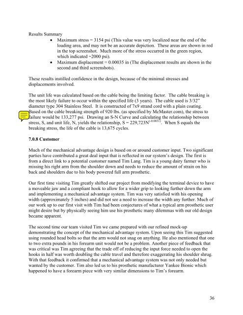
Results Summary<br />
• Maximum stress = 3154 psi (This value was very localized near the end of the<br />
loading area, and may not be an accurate depiction. These areas are shown in red<br />
in the top screenshot. Much more of the stress occurred in the green region,<br />
which indicated ~2000 psi).<br />
• Maximum displacement = 0.00035 in (The displacement results are shown in the<br />
second and third screenshots).<br />
These results instilled confidence in the design, because of the minimal stresses and<br />
displacements involved.<br />
The unit life was calculated based on the cable being the limiting factor. The cable breaking is<br />
the most likely failure to occur within the specified life (3 years). The cable used is 3/32”<br />
diameter type 304 Stainless Steel. It is constructed of 7x9 strand cord with a plain coating.<br />
Based on the cable breaking strength of 920 lbs. (as specified by McMaster.com), the stress to<br />
failure would be 133,277 psi. Drawing an S-N Curve and calculating the relationship between<br />
stress, S, and unit life, N, yields the relationship, S = 229,723N (-0.0851) . When S equals the<br />
breaking stress, the life of the cable is 13,675 cycles.<br />
7.0.8 Customer<br />
Much of the mechanical advantage design is based on or around customer input. Two significant<br />
parties have contributed a great deal input that is reflected in our system’s design. The first is<br />
from a direct link to a potential customer named Tim Lang. Tim is a young dairy farmer who is<br />
missing his right arm from the shoulder down and needs to reduce the amount of strain on his<br />
back and shoulders due to his body powered full arm prosthetic.<br />
Our first time visiting Tim greatly shifted our project from modifying the terminal device to have<br />
a moveable jaw and a compliant hook to allow for a wider grip to looking further down the arm<br />
and implementing a mechanical advantage system. Tim was very satisfied with his opening<br />
width (approximately 5 inches) and did not see a need to increase the width any further. Much of<br />
our work up to our first visit with Tim had been conjectures of what a typical arm prosthetic user<br />
might desire but by physically seeing him use his prosthetic many dilemmas with our old design<br />
became apparent.<br />
The second time our team visited Tim we came prepared with our refined mock-up<br />
demonstrating the concept of the mechanical advantage system. Upon seeing this Tim suggested<br />
using rounded head bolts so that the arm would not snag on anything. He also mentioned that one<br />
to two extra pounds in his forearm unit would not be a problem. Another piece of feedback that<br />
was critical was Tim agreeing that the trade off of reducing the input force needed to open the<br />
hooks in half was worth doubling the cable travel and therefore exaggerating his shoulder shrug.<br />
With that feedback it confirmed that a mechanical advantage system was not only needed but<br />
wanted by the customer. Tim also led us to his prosthetic manufacturer Yankee Bionic which<br />
happened to have a forearm piece with very similar dimensions to Tim’s forearm.<br />
36


