Prosthetic Arm Force Reducer Team 1 – Halliday's ... - Ohio University
Prosthetic Arm Force Reducer Team 1 – Halliday's ... - Ohio University
Prosthetic Arm Force Reducer Team 1 – Halliday's ... - Ohio University

You also want an ePaper? Increase the reach of your titles
YUMPU automatically turns print PDFs into web optimized ePapers that Google loves.
Another sector that has aided in our design is from the Bureau of Vocational Rehabilitation<br />
(BVR) specifically George Platounaris. The BVR is comprised of councilors who provide<br />
services leading to employment for people with physical and mental disabilities. Through<br />
George and his staff engineers he has confirmed that our design is well suited for our target<br />
customer, very marketable, and usable. This feedback is based on several customers that George<br />
and other councilors have worked with in the past.<br />
One other sector that has directed our design is from manufacturers of terminal devices,<br />
especially Otto Bock. Through contact with Otto Bock we have realized that our initial vector<br />
hook idea (having multiple resistive force settings) was not a new idea and that the very simple<br />
yet effective system they were using was the culmination of a lot of engineering and customer<br />
feedback.<br />
7.0.9 DFMA<br />
When exploring the design for manufacturing and assembly (DFMA) for the mechanical<br />
advantage module it is important to design each component based upon its manufacturability,<br />
dimensions, material, functionality, machinability, and other assembly considerations. By<br />
considering all of those items it will help to ensure a simple but yet effective design. Our module<br />
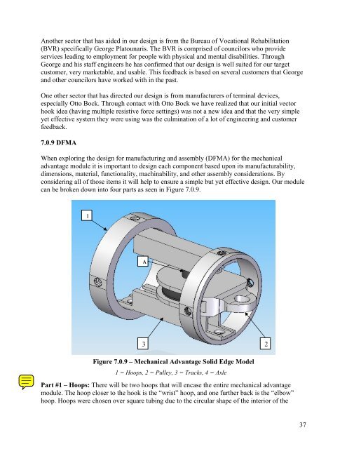
can be broken down into four parts as seen in Figure 7.0.9.<br />
1<br />
Ax<br />
3<br />
Figure 7.0.9 <strong>–</strong> Mechanical Advantage Solid Edge Model<br />
1 = Hoops, 2 = Pulley, 3 = Tracks, 4 = Axle<br />
Part #1 <strong>–</strong> Hoops: There will be two hoops that will encase the entire mechanical advantage<br />
module. The hoop closer to the hook is the “wrist” hoop, and one further back is the “elbow”<br />
hoop. Hoops were chosen over square tubing due to the circular shape of the interior of the<br />
2<br />
37