6 electrical reference – cable drawings - Norac
6 electrical reference – cable drawings - Norac
6 electrical reference – cable drawings - Norac

Create successful ePaper yourself
Turn your PDF publications into a flip-book with our unique Google optimized e-Paper software.
4.3 WING SENSOR INSTALLATION<br />
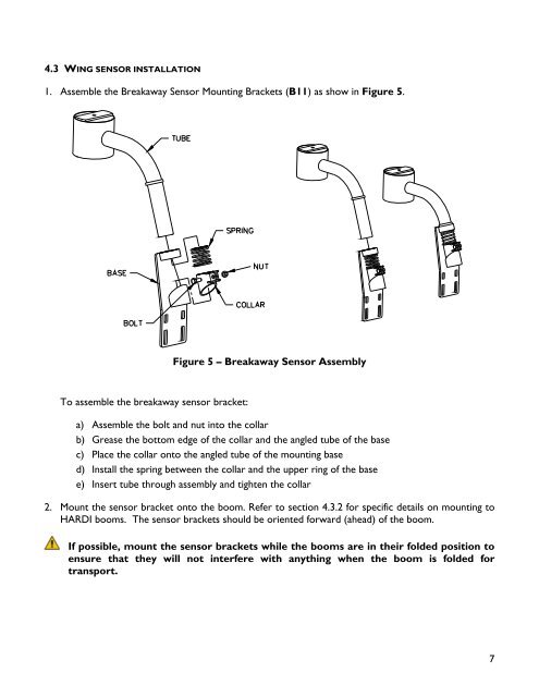
1. Assemble the Breakaway Sensor Mounting Brackets (B11) as show in Figure 5.<br />
To assemble the breakaway sensor bracket:<br />
Figure 5 – Breakaway Sensor Assembly<br />
a) Assemble the bolt and nut into the collar<br />
b) Grease the bottom edge of the collar and the angled tube of the base<br />
c) Place the collar onto the angled tube of the mounting base<br />
d) Install the spring between the collar and the upper ring of the base<br />
e) Insert tube through assembly and tighten the collar<br />
2. Mount the sensor bracket onto the boom. Refer to section 4.3.2 for specific details on mounting to<br />
HARDI booms. The sensor brackets should be oriented forward (ahead) of the boom.<br />
If possible, mount the sensor brackets while the booms are in their folded position to<br />
ensure that they will not interfere with anything when the boom is folded for<br />
transport.<br />
7