6 electrical reference – cable drawings - Norac
6 electrical reference – cable drawings - Norac
6 electrical reference – cable drawings - Norac

You also want an ePaper? Increase the reach of your titles
YUMPU automatically turns print PDFs into web optimized ePapers that Google loves.
3<br />
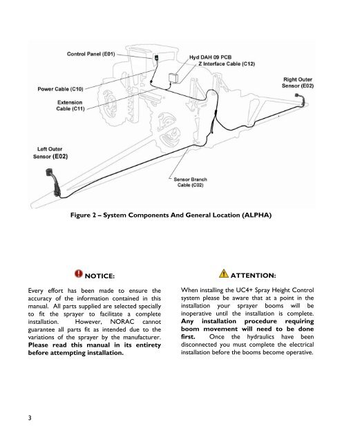
Figure 2 – System Components And General Location (ALPHA)<br />
NOTICE:<br />
Every effort has been made to ensure the<br />
accuracy of the information contained in this<br />
manual. All parts supplied are selected specially<br />
to fit the sprayer to facilitate a complete<br />
installation. However, NORAC cannot<br />
guarantee all parts fit as intended due to the<br />
variations of the sprayer by the manufacturer.<br />
Please read this manual in its entirety<br />
before attempting installation.<br />
ATTENTION:<br />
When installing the UC4+ Spray Height Control<br />
system please be aware that at a point in the<br />
installation your sprayer booms will be<br />
inoperative until the installation is complete.<br />
Any installation procedure requiring<br />
boom movement will need to be done<br />
first. Once the hydraulics have been<br />
disconnected you must complete the <strong>electrical</strong><br />
installation before the booms become operative.