6 electrical reference – cable drawings - Norac
6 electrical reference – cable drawings - Norac
6 electrical reference – cable drawings - Norac

Create successful ePaper yourself
Turn your PDF publications into a flip-book with our unique Google optimized e-Paper software.
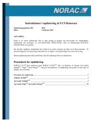
11. Connect the black wire with spade connector on C12 to the GND on the DAH09 board (Figure<br />
22).<br />
20<br />
12 VDC and GND<br />
Figure 22: DAH09 PCB for Autoslant<br />
DIP switches<br />
12. Configure the system for Autoslant by setting the DIP switches on DAH09 board:<br />
a) Set DIP switches 2,3,4,5,6, and 8 to ON. Set DIP switch 7 to OFF (Figure 23).<br />
Figure 23: Suggested Default Setting for DIP Switches 2-8 for AUTOSLANT<br />
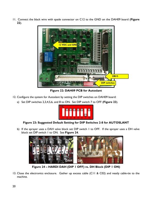
b) If the sprayer uses a DAH valve block set DIP switch 1 to OFF. If the sprayer uses a DH valve<br />
block set DIP switch 1 to ON. See Figure 24.<br />
Figure 24 – HARDI DAH (DIP 1 OFF) vs. DH Block (DIP 1 ON)<br />
13. Close the electronics enclosure. Gather up excess <strong>cable</strong> (C11 & C02) and neatly <strong>cable</strong>-tie to the<br />
machine.<br />
DB15