6 electrical reference – cable drawings - Norac
6 electrical reference – cable drawings - Norac
6 electrical reference – cable drawings - Norac

Create successful ePaper yourself
Turn your PDF publications into a flip-book with our unique Google optimized e-Paper software.
Notice:<br />
Additional instructions are available in the UC4+BC+HD4-INSTE (End-user manual) for configuring<br />
spray ON/OFF signal sensing and headland modes. With these features the Autoslant system will<br />
function together with the spray signal, switching boom height control on and off with the spray signal.<br />
This function can also be configured to raise the boom automatically for headland turning. Refer to the<br />
HD4 end-user manual for more information. These additional features described are only available<br />
when using the HARDI DAH09 PCB.<br />
This is only appli<strong>cable</strong> for systems using the DAH09 interface and with harness 44658-78.<br />
Notice:<br />
Some sprayers have been found to have the slant functions wired differently than others. To interface<br />
the UC4+ system to the sprayer it will be necessary to adjust the wiring on the 44658-78 interface PCB<br />
(item C12) or 44658-51 (C12A), depending on the type of install.<br />
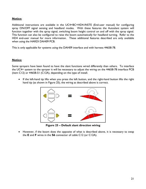
� If the left-hand tip lifts when you press the left button, and the right-hand button lifts the right<br />
hand tip (as shown in Figure 25), the wiring as described above is correct.<br />
Figure 25 – Default slant direction wiring<br />
� However, if the boom does the opposite of what is described above, it is necessary to swap<br />
the E and F wires in the S6 connector of <strong>cable</strong> C12 (or C12A).<br />
21