6 electrical reference – cable drawings - Norac
6 electrical reference – cable drawings - Norac
6 electrical reference – cable drawings - Norac

You also want an ePaper? Increase the reach of your titles
YUMPU automatically turns print PDFs into web optimized ePapers that Google loves.
18<br />
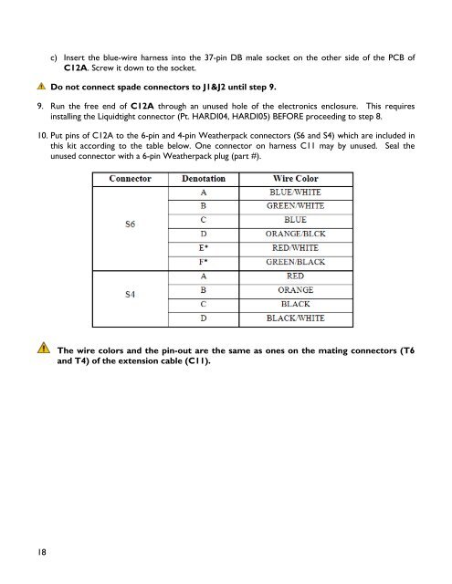
c) Insert the blue-wire harness into the 37-pin DB male socket on the other side of the PCB of<br />
C12A. Screw it down to the socket.<br />
Do not connect spade connectors to J1&J2 until step 9.<br />
9. Run the free end of C12A through an unused hole of the electronics enclosure. This requires<br />
installing the Liquidtight connector (Pt. HARDI04, HARDI05) BEFORE proceeding to step 8.<br />
10. Put pins of C12A to the 6-pin and 4-pin Weatherpack connectors (S6 and S4) which are included in<br />
this kit according to the table below. One connector on harness C11 may by unused. Seal the<br />
unused connector with a 6-pin Weatherpack plug (part #).<br />
The wire colors and the pin-out are the same as ones on the mating connectors (T6<br />
and T4) of the extension <strong>cable</strong> (C11).