SPARC Enterprise T5120 and T5220 Servers Service Manual - Fujitsu
SPARC Enterprise T5120 and T5220 Servers Service Manual - Fujitsu
SPARC Enterprise T5120 and T5220 Servers Service Manual - Fujitsu

Create successful ePaper yourself
Turn your PDF publications into a flip-book with our unique Google optimized e-Paper software.
<strong>Manual</strong> Code C120-E463-04EN<br />
Part No. 875-4194-13<br />
July 2009, Revision A<br />
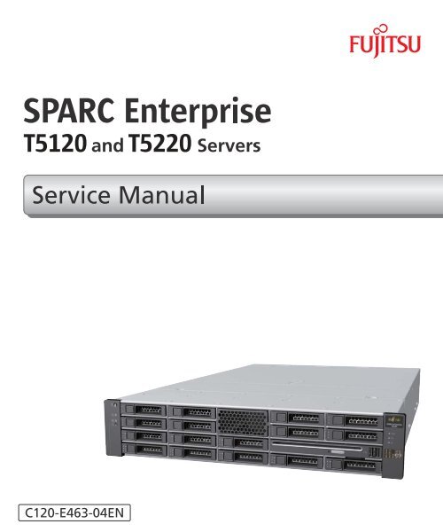
<strong>SPARC</strong> <strong>Enterprise</strong> TM<br />
<strong>T5120</strong> <strong>and</strong> <strong>T5220</strong> <strong>Servers</strong><br />
<strong>Service</strong> <strong>Manual</strong>
Copyright © 2009 Sun Microsystems, Inc., 4150 Network Circle, Santa Clara, California 95054, U.S.A. All rights reserved.<br />
FUJITSU LIMITED provided technical input <strong>and</strong> review on portions of this material.<br />
Sun Microsystems, Inc. <strong>and</strong> <strong>Fujitsu</strong> Limited each own or control intellectual property rights relating to products <strong>and</strong> technology described in<br />
this document, <strong>and</strong> such products, technology <strong>and</strong> this document are protected by copyright laws, patents <strong>and</strong> other intellectual property laws<br />
<strong>and</strong> international treaties. The intellectual property rights of Sun Microsystems, Inc. <strong>and</strong> <strong>Fujitsu</strong> Limited in such products, technology <strong>and</strong> this<br />
document include, without limitation, one or more of the United States patents listed at http://www.sun.com/patents <strong>and</strong> one or more<br />
additional patents or patent applications in the United States or other countries.<br />
This document <strong>and</strong> the product <strong>and</strong> technology to which it pertains are distributed under licenses restricting their use, copying, distribution,<br />
<strong>and</strong> decompilation. No part of such product or technology, or of this document, may be reproduced in any form by any means without prior<br />
written authorization of <strong>Fujitsu</strong> Limited <strong>and</strong> Sun Microsystems, Inc., <strong>and</strong> their applicable licensors, if any. The furnishing of this document to<br />
you does not give you any rights or licenses, express or implied, with respect to the product or technology to which it pertains, <strong>and</strong> this<br />
document does not contain or represent any commitment of any kind on the part of <strong>Fujitsu</strong> Limited or Sun Microsystems, Inc., or any affiliate of<br />
either of them.<br />
This document <strong>and</strong> the product <strong>and</strong> technology described in this document may incorporate third-party intellectual property copyrighted by<br />
<strong>and</strong>/or licensed from suppliers to <strong>Fujitsu</strong> Limited <strong>and</strong>/or Sun Microsystems, Inc., including software <strong>and</strong> font technology.<br />
Per the terms of the GPL or LGPL, a copy of the source code governed by the GPL or LGPL, as applicable, is available upon request by the End<br />
User. Please contact <strong>Fujitsu</strong> Limited or Sun Microsystems, Inc.<br />
This distribution may include materials developed by third parties.<br />
Parts of the product may be derived from Berkeley BSD systems, licensed from the University of California. UNIX is a registered trademark in<br />
the U.S. <strong>and</strong> in other countries, exclusively licensed through X/Open Company, Ltd.<br />
Sun, Sun Microsystems, the Sun logo © , Java, Netra, Solaris, Sun StorageTek, docs.sun.comSM , OpenBoot, SunVTS, Sun Fire,<br />
SunSolveSM , CoolThreads, <strong>and</strong> J2EE, are trademarks or registered trademarks of Sun Microsystems, Inc. or its subsidiaries in the U.S. <strong>and</strong><br />
other countries.<br />
<strong>Fujitsu</strong> <strong>and</strong> the <strong>Fujitsu</strong> logo are registered trademarks of <strong>Fujitsu</strong> Limited.<br />
All <strong>SPARC</strong> trademarks are used under license <strong>and</strong> are registered trademarks of <strong>SPARC</strong> International, Inc. in the U.S. <strong>and</strong> other countries.<br />
Products bearing <strong>SPARC</strong> trademarks are based upon architecture developed by Sun Microsystems, Inc.<br />
<strong>SPARC</strong>64 is a trademark of <strong>SPARC</strong> International, Inc., used under license by <strong>Fujitsu</strong> Microelectronics, Inc. <strong>and</strong> <strong>Fujitsu</strong> Limited.<br />
SSH is a registered trademark of SSH Communications Security in the United States <strong>and</strong> in certain other jurisdictions.<br />
The OPEN LOOK <strong>and</strong> Sun Graphical User Interface was developed by Sun Microsystems, Inc. for its users <strong>and</strong> licensees. Sun acknowledges<br />
the pioneering efforts of Xerox in researching <strong>and</strong> developing the concept of visual or graphical user interfaces for the computer industry. Sun<br />
holds a non-exclusive license from Xerox to the Xerox Graphical User Interface, which license also covers Sun’s licensees who implement OPEN<br />
LOOK GUIs <strong>and</strong> otherwise comply with Sun’s written license agreements.<br />
United States Government Rights - Commercial use. U.S. Government users are subject to the st<strong>and</strong>ard government user license agreements of<br />
Sun Microsystems, Inc. <strong>and</strong> <strong>Fujitsu</strong> Limited <strong>and</strong> the applicable provisions of the FAR <strong>and</strong> its supplements.<br />
Disclaimer: The only warranties granted by <strong>Fujitsu</strong> Limited, Sun Microsystems, Inc. or any affiliate of either of them in connection with this<br />
document or any product or technology described herein are those expressly set forth in the license agreement pursuant to which the product or<br />
technology is provided.<br />
EXCEPT AS EXPRESSLY SET FORTH IN SUCH AGREEMENT, FUJITSU LIMITED, SUN MICROSYSTEMS, INC. AND THEIR AFFILIATES<br />
MAKE NO REPRESENTATIONS OR WARRANTIES OF ANY KIND (EXPRESS OR IMPLIED) REGARDING SUCH PRODUCT OR<br />
TECHNOLOGY OR THIS DOCUMENT, WHICH ARE ALL PROVIDED AS IS, AND ALL EXPRESS OR IMPLIED CONDITIONS,<br />
REPRESENTATIONS AND WARRANTIES, INCLUDING WITHOUT LIMITATION ANY IMPLIED WARRANTY OF MERCHANTABILITY,<br />
FITNESS FOR A PARTICULAR PURPOSE OR NON-INFRINGEMENT, ARE DISCLAIMED, EXCEPT TO THE EXTENT THAT SUCH<br />
DISCLAIMERS ARE HELD TO BE LEGALLY INVALID.<br />
Unless otherwise expressly set forth in such agreement, to the extent allowed by applicable law, in no event shall <strong>Fujitsu</strong> Limited, Sun<br />
Microsystems, Inc. or any of their affiliates have any liability to any third party under any legal theory for any loss of revenues or profits, loss of<br />
use or data, or business interruptions, or for any indirect, special, incidental or consequential damages, even if advised of the possibility of such<br />
damages.<br />
DOCUMENTATION IS PROVIDED “AS IS” AND ALL EXPRESS OR IMPLIED CONDITIONS, REPRESENTATIONS AND WARRANTIES,<br />
INCLUDING ANY IMPLIED WARRANTY OF MERCHANTABILITY, FITNESS FOR A PARTICULAR PURPOSE OR NON-INFRINGEMENT,<br />
ARE DISCLAIMED, EXCEPT TO THE EXTENT THAT SUCH DISCLAIMERS ARE HELD TO BE LEGALLY INVALID.<br />
Please<br />
Recycle
Copyright © 2009 Sun Microsystems, Inc., 4150 Network Circle, Santa Clara, California 95054, Etats-Unis. Tous droits réservés.<br />
Entrée et revue tecnical fournies par FUJITSU LIMITED sur des parties de ce matériel.<br />
Sun Microsystems, Inc. et <strong>Fujitsu</strong> Limited détiennent et contrôlent toutes deux des droits de propriété intellectuelle relatifs aux produits et<br />
technologies décrits dans ce document. De même, ces produits, technologies et ce document sont protégés par des lois sur le copyright, des<br />
brevets, d’autres lois sur la propriété intellectuelle et des traités internationaux. Les droits de propriété intellectuelle de Sun Microsystems, Inc.<br />
et <strong>Fujitsu</strong> Limited concernant ces produits, ces technologies et ce document comprennent, sans que cette liste soit exhaustive, un ou plusieurs<br />
des brevets déposés aux États-Unis et indiqués à l’adresse http://www.sun.com/patents de même qu’un ou plusieurs brevets ou applications<br />
brevetées supplémentaires aux États-Unis et dans d’autres pays.<br />
Ce document, le produit et les technologies afférents sont exclusivement distribués avec des licences qui en restreignent l’utilisation, la copie, la<br />
distribution et la décompilation. Aucune partie de ce produit, de ces technologies ou de ce document ne peut être reproduite sous quelque<br />
forme que ce soit, par quelque moyen que ce soit, sans l’autorisation écrite préalable de <strong>Fujitsu</strong> Limited et de Sun Microsystems, Inc., et de leurs<br />
éventuels bailleurs de licence. Ce document, bien qu’il vous ait été fourni, ne vous confère aucun droit et aucune licence, expresses ou tacites,<br />
concernant le produit ou la technologie auxquels il se rapporte. Par ailleurs, il ne contient ni ne représente aucun engagement, de quelque type<br />
que ce soit, de la part de <strong>Fujitsu</strong> Limited ou de Sun Microsystems, Inc., ou des sociétés affiliées.<br />
Ce document, et le produit et les technologies qu’il décrit, peuvent inclure des droits de propriété intellectuelle de parties tierces protégés par<br />
copyright et/ou cédés sous licence par des fournisseurs à <strong>Fujitsu</strong> Limited et/ou Sun Microsystems, Inc., y compris des logiciels et des<br />
technologies relatives aux polices de caractères.<br />
Par limites du GPL ou du LGPL, une copie du code source régi par le GPL ou LGPL, comme applicable, est sur dem<strong>and</strong>e vers la fin utilsateur<br />
disponible; veuillez contacter <strong>Fujitsu</strong> Limted ou Sun Microsystems, Inc.<br />
Cette distribution peut comprendre des composants développés par des tierces parties.<br />
Des parties de ce produit pourront être dérivées des systèmes Berkeley BSD licenciés par l’Université de Californie. UNIX est une marque<br />
déposée aux Etats-Unis et dans d’autres pays et licenciée exclusivement par X/Open Company, Ltd.<br />
Sun, Sun Microsystems, le logo Sun © , Java, Netra, Solaris, Sun StorageTek, docs.sun.comSM , OpenBoot, SunVTS, Sun Fire,<br />
SunSolveSM , CoolThreads, et J2EE sont des marques de fabrique ou des marques déposées de Sun Microsystems, Inc. , ou ses filiales aux<br />
Etats-Unis et dans d’autres pays.<br />
<strong>Fujitsu</strong> et le logo <strong>Fujitsu</strong> sont des marques déposées de <strong>Fujitsu</strong> Limited.<br />
Toutes les marques <strong>SPARC</strong> sont utilisées sous licence et sont des marques de fabrique ou des marques déposées de <strong>SPARC</strong> International, Inc.<br />
aux Etats-Unis et dans d’autres pays. Les produits portant les marques <strong>SPARC</strong> sont basés sur une architecture développée par Sun<br />
Microsystems, Inc.<br />
<strong>SPARC</strong>64 est une marques déposée de <strong>SPARC</strong> International, Inc., utilisée sous le permis par <strong>Fujitsu</strong> Microelectronics, Inc. et <strong>Fujitsu</strong> Limited.<br />
SSH est une marque déposée registre de SSH Communications Security aux Etats-Uniset dans certaines autres juridictions.<br />
L’interface d’utilisation graphique OPEN LOOK et Sun a été développée par Sun Microsystems, Inc. pour ses utilisateurs et licenciés. Sun<br />
reconnaît les efforts de pionniers de Xerox pour la recherche et le développement du concept des interfaces d’utilisation visuelle ou graphique<br />
pour l’industrie de l’informatique. Sun détient une license non exclusive de Xerox sur l’interface d’utilisation graphique Xerox, cette licence<br />
couvrant également les licenciés de Sun qui mettent en place l’interface d’utilisation graphique OPEN LOOK et qui, en outre, se conforment aux<br />
licences écrites de Sun.<br />
Droits du gouvernement américain - logiciel commercial. Les utilisateurs du gouvernement américain sont soumis aux contrats de licence<br />
st<strong>and</strong>ard de Sun Microsystems, Inc. et de <strong>Fujitsu</strong> Limited ainsi qu’aux clauses applicables stipulées dans le FAR et ses suppléments.<br />
Avis de non-responsabilité: les seules garanties octroyées par <strong>Fujitsu</strong> Limited, Sun Microsystems, Inc. ou toute société affiliée de l’une ou l’autre<br />
entité en rapport avec ce document ou tout produit ou toute technologie décrit(e) dans les présentes correspondent aux garanties expressément<br />
stipulées dans le contrat de licence régissant le produit ou la technologie fourni(e).<br />
SAUF MENTION CONTRAIRE EXPRESSÉMENT STIPULÉE DANS CE CONTRAT, FUJITSU LIMITED, SUN MICROSYSTEMS, INC. ET LES<br />
SOCIÉTÉS AFFILIÉES REJETTENT TOUTE REPRÉSENTATION OU TOUTE GARANTIE, QUELLE QU’EN SOIT LA NATURE (EXPRESSE<br />
OU IMPLICITE) CONCERNANT CE PRODUIT, CETTE TECHNOLOGIE OU CE DOCUMENT, LESQUELS SONT FOURNIS EN L’ÉTAT. EN<br />
OUTRE, TOUTES LES CONDITIONS, REPRÉSENTATIONS ET GARANTIES EXPRESSES OU TACITES, Y COMPRIS NOTAMMENT TOUTE<br />
GARANTIE IMPLICITE RELATIVE À LA QUALITÉ MARCHANDE, À L’APTITUDE À UNE UTILISATION PARTICULIÈRE OU À<br />
L’ABSENCE DE CONTREFAÇON, SONT EXCLUES, DANS LA MESURE AUTORISÉE PAR LA LOI APPLICABLE.<br />
Sauf mention contraire expressément stipulée dans ce contrat, dans la mesure autorisée par la loi applicable, en aucun cas <strong>Fujitsu</strong> Limited, Sun<br />
Microsystems, Inc. ou l’une de leurs filiales ne sauraient être tenues responsables envers une quelconque partie tierce, sous quelque théorie<br />
juridique que ce soit, de tout manque à gagner ou de perte de profit, de problèmes d’utilisation ou de perte de données, ou d’interruptions<br />
d’activités, ou de tout dommage indirect, spécial, secondaire ou consécutif, même si ces entités ont été préalablement informées d’une telle<br />
éventualité.<br />
LA DOCUMENTATION EST FOURNIE “EN L’ETAT” ET TOUTES AUTRES CONDITIONS, DECLARATIONS ET GARANTIES EXPRESSES<br />
OU TACITES SONT FORMELLEMENT EXCLUES, DANS LA MESURE AUTORISEE PAR LA LOI APPLICABLE, Y COMPRIS NOTAMMENT<br />
TOUTE GARANTIE IMPLICITE RELATIVE A LA QUALITE MARCHANDE, A L’APTITUDE A UNE UTILISATION PARTICULIERE OU A<br />
L’ABSENCE DE CONTREFACON.
Contents<br />
Preface xiii<br />
Identifying Server Components 1<br />
Infrastructure Boards in <strong>SPARC</strong> <strong>Enterprise</strong> <strong>T5120</strong> <strong>Servers</strong> 2<br />
Infrastructure Boards in <strong>SPARC</strong> <strong>Enterprise</strong> <strong>T5220</strong> <strong>Servers</strong> 3<br />
Internal System Cables for <strong>SPARC</strong> <strong>Enterprise</strong> <strong>T5120</strong> <strong>Servers</strong> 4<br />
Internal System Cables for <strong>SPARC</strong> <strong>Enterprise</strong> <strong>T5220</strong> <strong>Servers</strong> 5<br />
Front Panel Controls <strong>and</strong> Indicators on <strong>SPARC</strong> <strong>Enterprise</strong> <strong>T5120</strong> <strong>Servers</strong> 5<br />
Rear Panel Components <strong>and</strong> Indicators on <strong>SPARC</strong> <strong>Enterprise</strong> <strong>T5120</strong> <strong>Servers</strong><br />
8<br />
Front Panel Controls <strong>and</strong> Indicators on <strong>SPARC</strong> <strong>Enterprise</strong> <strong>T5220</strong> <strong>Servers</strong> 9<br />
Rear Panel Components <strong>and</strong> Indicators on <strong>SPARC</strong> <strong>Enterprise</strong> <strong>T5220</strong> <strong>Servers</strong><br />
12<br />
Status LEDs for Ethernet Ports <strong>and</strong> Network Management Port 14<br />
Detecting <strong>and</strong> Managing Faults 15<br />
Diagnostic Tools Overview 15<br />
<strong>Service</strong> Processor Interfaces 16<br />
Diagnostics Tools Quick Reference 17<br />
LED Overview 21<br />
Detecting Faults With ILOM 22<br />
ILOM Troubleshooting Overview 23<br />
Methods for Connecting to the <strong>Service</strong> Processor 24<br />
v
How to Switch From the System Console to the <strong>Service</strong> Processor 25<br />
How to Switch From the <strong>Service</strong> Processor to the System Console 25<br />
<strong>Service</strong>-Related ILOM Comm<strong>and</strong> Summary 26<br />
Faults Displayed by show faulty 29<br />
Example of show faulty Output When No Fault is Present 30<br />
Example of show faulty Output for Environmental Faults 30<br />
Example of show faulty Output for Faults Detected by POST 30<br />
Example of show faulty Output for Faults Detected by PSH<br />
Technology 30<br />
▼ Clear FRU Faults <strong>Manual</strong>ly 31<br />
▼ Display FRU Information With the show Comm<strong>and</strong> 32<br />
▼ Create an ALOM CMT Shell 32<br />
Detecting Faults With POST 34<br />
POST Overview 35<br />
Managing POST Operations 35<br />
ILOM Properties that Affect POST Behavior 35<br />
Examples of POST Management 37<br />
keyswitch_state Set to normal 38<br />
keyswitch_state Set to diag 38<br />
diag_mode Set to off 38<br />
diag_mode Set to service 38<br />
▼ Run POST in Maximum Mode 39<br />
▼ Clear POST-Detected Faults 41<br />
POST Output Quick Reference 42<br />
Managing Faults Using the PSH Feature 43<br />
Solaris PSH Feature Overview 44<br />
PSH-Detected Fault Console Message 45<br />
▼ Identify PSH-Detected Faults With fmdump 45<br />
▼ Clear PSH-Detected Faults 47<br />
vi <strong>SPARC</strong> <strong>Enterprise</strong> <strong>T5120</strong> <strong>and</strong> <strong>T5220</strong> <strong>Servers</strong> <strong>Service</strong> <strong>Manual</strong> • July 2009
Viewing Solaris OS Messages 48<br />
▼ Check the Message Buffer 49<br />
▼ View the System Message Log Files 49<br />
Managing Components With Automatic System Recovery Comm<strong>and</strong>s 50<br />
ASR Overview 50<br />
▼ Display System Components 51<br />
▼ Disable System Components 52<br />
▼ Enable System Components 53<br />
Detecting Faults Using SunVTS Software 53<br />
▼ Run the SunVTS Software 54<br />
Preparing to <strong>Service</strong> the System 57<br />
General Safety Information 57<br />
Safety Symbols 57<br />
Electrostatic Discharge Safety Measures 58<br />
Antistatic Wrist Strap Use 58<br />
Antistatic Mat 59<br />
Essential Tools 59<br />
▼ Find the Chassis Serial Number 59<br />
Removing Power From the System 60<br />
▼ Power Off the Server (<strong>Service</strong> Processor Comm<strong>and</strong>) 60<br />
▼ Power Off the Server (Power Button - Graceful) 62<br />
▼ Power Off the Server (Emergency Shutdown) 62<br />
▼ Disconnect Power Cords From the Server 62<br />
Positioning the System for Servicing 62<br />
▼ Extend the Server to the Maintenance Position 63<br />
▼ Remove the Server From the Rack 64<br />
Accessing Internal Components 66<br />
▼ Perform Electrostatic Discharge Prevention Measures 67<br />
Contents vii
▼ Remove the Top Cover 67<br />
Servicing Hard Drives 69<br />
Hard Drive Servicing Overview 69<br />
Hard Drive LEDs 70<br />
▼ Remove a Hard Drive 71<br />
▼ Install a Hard Drive 73<br />
Four-Drive Capable Backplane Configuration Reference 77<br />
Eight-Drive Capable Backplane Configuration Reference 78<br />
Sixteen-Drive Capable Backplane Configuration Reference 79<br />
Servicing Motherboard Components 81<br />
Servicing FB-DIMMs 81<br />
Memory Fault H<strong>and</strong>ling Overview 82<br />
▼ Identify Faulty FB-DIMMs Using the show faulty Comm<strong>and</strong> 83<br />
▼ Identify Faulty FB-DIMMs Using the FB-DIMM Fault Locator<br />
Button 83<br />
▼ Remove FB-DIMMs 85<br />
▼ Install Replacement FB-DIMMs 87<br />
▼ Verify Successful Replacement of Faulty FB-DIMMs 89<br />
▼ Upgrade Memory Configuration With Additional FB-DIMMs 91<br />
FB-DIMM Configuration Guidelines 95<br />
Guidelines for Upgrading Memory 95<br />
When Replacing Faulty FB-DIMMs 95<br />
FB-DIMM Configuration Reference 96<br />
Servicing the Air Duct 100<br />
▼ Remove the Air Duct 100<br />
▼ Install the Air Duct 101<br />
Servicing PCIe/XAUI Risers 102<br />
PCIe/XAUI Riser Overview 102<br />
viii <strong>SPARC</strong> <strong>Enterprise</strong> <strong>T5120</strong> <strong>and</strong> <strong>T5220</strong> <strong>Servers</strong> <strong>Service</strong> <strong>Manual</strong> • July 2009
▼ Remove a PCIe/XAUI Riser 102<br />
▼ Install a PCIe/XAUI Riser 104<br />
▼ Remove a PCIe or XAUI Card 106<br />
▼ Install a PCIe or XAUI Card 107<br />
PCIe/XAUI Card Configuration Reference for <strong>SPARC</strong> <strong>Enterprise</strong> <strong>T5120</strong><br />
<strong>Servers</strong> 110<br />
PCIe <strong>and</strong> XAUI Card Reference for <strong>SPARC</strong> <strong>Enterprise</strong> <strong>T5220</strong> <strong>Servers</strong> 111<br />
Servicing the Battery 112<br />
System Battery Overview 112<br />
▼ Remove a Battery 113<br />
▼ Install a Battery 114<br />
Servicing the SCC Module 114<br />
SCC Module Overview 114<br />
▼ Remove a Faulty SCC Module 115<br />
▼ Install a New SCC Module 116<br />
Servicing the Motherboard Assembly 117<br />
Motherboard Servicing Overview 117<br />
▼ Remove the Motherboard Assembly 118<br />
▼ Install the Motherboard Assembly 120<br />
Servicing Fan Modules 123<br />
Fan Module Overview 123<br />
Fan Module Configurations for <strong>SPARC</strong> <strong>Enterprise</strong> <strong>T5120</strong> <strong>Servers</strong> (4- <strong>and</strong> 8-<br />
Disk Capable) 124<br />
Fan Module Configurations for <strong>SPARC</strong> <strong>Enterprise</strong> <strong>T5220</strong> <strong>Servers</strong> (8- <strong>and</strong><br />
16-Disk Capable) 124<br />
Fan Module Status LEDs 125<br />
▼ Remove a Fan Module 125<br />
▼ Install a Fan Module 127<br />
Contents ix
Servicing Power Supplies 129<br />
Power Supplies Overview 129<br />
Power Supply Status LEDs 129<br />
▼ Remove a Power Supply 131<br />
▼ Install a Power Supply 134<br />
Power Supply Configuration Reference 136<br />
Servicing Boards <strong>and</strong> Components 137<br />
Important Safety Instructions 137<br />
Servicing DVD/USB Modules 138<br />
DVD/USB Module Overview 139<br />
▼ Remove the DVD/USB Module 139<br />
▼ Install the DVD/USB Module 141<br />
Servicing Fan Power Boards 143<br />
Fan Power Board Overview 143<br />
▼ Remove the Fan Power Board 143<br />
▼ Install the Fan Power Board 145<br />
Servicing the Hard Drive Cage 146<br />
Hard Drive Cage Overview 146<br />
▼ Remove the Hard Drive Cage 146<br />
▼ Install the Hard Drive Cage 149<br />
Servicing the Hard Drive Backplane 152<br />
Hard Drive Backplane Overview 152<br />
▼ Remove the Hard Drive Backplane 152<br />
▼ Install the Hard Drive Backplane 154<br />
Servicing Front Control Panel Light Pipe Assemblies 156<br />
Front Control Panel Light Pipe Assemblies Overview 157<br />
▼ Remove the Front Control Panel Light Pipe Assemblies 157<br />
▼ Install the Front Control Panel Light Pipe Assemblies 158<br />
x <strong>SPARC</strong> <strong>Enterprise</strong> <strong>T5120</strong> <strong>and</strong> <strong>T5220</strong> <strong>Servers</strong> <strong>Service</strong> <strong>Manual</strong> • July 2009
Servicing Power Distribution Boards 160<br />
Power Distribution Board Overview 160<br />
▼ Remove the Power Distribution Board 161<br />
▼ Install the Power Distribution Board 163<br />
Servicing Power Supply Backplanes (<strong>SPARC</strong> <strong>Enterprise</strong> <strong>T5220</strong> <strong>Servers</strong>) 167<br />
Power Supply Backplane Overview 168<br />
▼ Remove the Power Supply Backplane 168<br />
▼ Install the Power Supply Backplane 170<br />
Servicing Paddle Cards 171<br />
Paddle Card Overview 172<br />
▼ Remove the Paddle Card 172<br />
▼ Install the Paddle Card 173<br />
Returning the Server to Operation 175<br />
▼ Install the Top Cover 175<br />
▼ Reinstall the Server in the Rack 176<br />
▼ Return the Server to the Normal Rack Position 177<br />
▼ Connect Power Cords to the Server 178<br />
▼ Power On the Server Using the poweron Comm<strong>and</strong> 179<br />
▼ Power On the Server Using the Front Panel Power Button 180<br />
Identifying FRUs in <strong>SPARC</strong> <strong>Enterprise</strong> <strong>T5120</strong> <strong>Servers</strong> 181<br />
Motherboard Components in <strong>T5120</strong> <strong>Servers</strong> 182<br />
I/O Components in <strong>SPARC</strong> <strong>Enterprise</strong> <strong>T5120</strong> <strong>Servers</strong> 184<br />
Power Distribution/Fan Module Components in <strong>SPARC</strong> <strong>Enterprise</strong> <strong>T5120</strong><br />
<strong>Servers</strong> 186<br />
Internal Cables for Onboard SAS Controller Cards in <strong>SPARC</strong> <strong>Enterprise</strong> <strong>T5120</strong><br />
<strong>Servers</strong> 188<br />
HDD Data Cable Routing for SAS RAID Controller Cards in Four-Disk<br />
Capable <strong>SPARC</strong> <strong>Enterprise</strong> <strong>T5120</strong> <strong>Servers</strong> 191<br />
Contents xi
HDD Data Cable Routing for SAS RAID Controller Cards in Eight-Disk<br />
Capable <strong>SPARC</strong> <strong>Enterprise</strong> <strong>T5120</strong> <strong>Servers</strong> 193<br />
Identifying FRUs in <strong>SPARC</strong> <strong>Enterprise</strong> <strong>T5220</strong> <strong>Servers</strong> 195<br />
Motherboard Components in <strong>T5220</strong> <strong>Servers</strong> 196<br />
I/O Components in <strong>SPARC</strong> <strong>Enterprise</strong> <strong>T5220</strong> <strong>Servers</strong> 198<br />
Power Distribution/Fan Module Components in <strong>SPARC</strong> <strong>Enterprise</strong> <strong>T5220</strong><br />
<strong>Servers</strong> 200<br />
Internal Cables for Onboard SAS Controller Cards in <strong>SPARC</strong> <strong>Enterprise</strong> <strong>T5220</strong><br />
<strong>Servers</strong> 202<br />
HDD Data Cable Routing for SAS RAID Controller Cards in <strong>SPARC</strong> <strong>Enterprise</strong><br />
<strong>T5220</strong> <strong>Servers</strong> 206<br />
Index 209<br />
xii <strong>SPARC</strong> <strong>Enterprise</strong> <strong>T5120</strong> <strong>and</strong> <strong>T5220</strong> <strong>Servers</strong> <strong>Service</strong> <strong>Manual</strong> • July 2009
Preface<br />
This manual provides detailed procedures that describe the removal <strong>and</strong> replacement<br />
of replaceable parts in the <strong>SPARC</strong> <strong>Enterprise</strong> <strong>T5120</strong> <strong>and</strong> <strong>T5220</strong> servers. This manual<br />
also includes information about the use <strong>and</strong> maintenance of the servers. This<br />
document is written for technicians, system administrators, authorized service<br />
providers (ASPs), <strong>and</strong> users who have advanced experience troubleshooting <strong>and</strong><br />
replacing hardware.<br />
For Safe Operation<br />
This manual contains important information regarding the use <strong>and</strong> h<strong>and</strong>ling of this<br />
product. Read this manual thoroughly. Pay special attention to the section “Notes on<br />
Safety” on page xix. Use the product according to the instructions <strong>and</strong> information<br />
available in this manual. Keep this manual h<strong>and</strong>y for further reference.<br />
Keep this manual h<strong>and</strong>y for further reference. <strong>Fujitsu</strong> makes every effort to prevent<br />
users <strong>and</strong> byst<strong>and</strong>ers from being injured or from suffering damage to their property.<br />
Use the product according to this manual.<br />
Before You Read This Document<br />
To fully use the information in this document, you must have thorough knowledge of<br />
the topics discussed in the <strong>SPARC</strong> <strong>Enterprise</strong> <strong>T5120</strong> <strong>and</strong> <strong>T5220</strong> <strong>Servers</strong> Product Notes.<br />
xiii
Structure <strong>and</strong> Contents of This <strong>Manual</strong><br />
This manual is organized as described below:<br />
■ “Identifying Server Components” on page 1<br />
Identifies key components of the <strong>SPARC</strong> <strong>Enterprise</strong> <strong>T5120</strong> <strong>and</strong> <strong>T5220</strong> servers,<br />
including major boards <strong>and</strong> internal system cables, as well as front <strong>and</strong> rear panel<br />
features.<br />
■ “Detecting <strong>and</strong> Managing Faults” on page 15<br />
Describes the diagnostics that are available for monitoring <strong>and</strong> troubleshooting<br />
the server.<br />
■ “Preparing to <strong>Service</strong> the System” on page 57<br />
Describes the steps necessary to prepare the servers for service.<br />
■ “Servicing Hard Drives” on page 69<br />
Explains how to remove <strong>and</strong> install hard drives.<br />
■ “Servicing Motherboard Components” on page 81<br />
Explains how to replace the motherboard <strong>and</strong> its components.<br />
■ “Servicing Fan Modules” on page 123<br />
Explains how to service faulty fan modules.<br />
■ “Servicing Power Supplies” on page 129<br />
Explains how to remove <strong>and</strong> replace power supply modules.<br />
■ “Servicing Boards <strong>and</strong> Components” on page 137<br />
Explains how to service infrastructure boards <strong>and</strong> components.<br />
■ “Returning the Server to Operation” on page 175<br />
Describes how to bring the server back to operation after performing service<br />
procedures.<br />
■ “Identifying FRUs in <strong>SPARC</strong> <strong>Enterprise</strong> <strong>T5120</strong> <strong>Servers</strong>” on page 181<br />
Identifies <strong>and</strong> illustrates Field Replaceable Units (FRUs) contained in <strong>SPARC</strong><br />
<strong>Enterprise</strong> <strong>T5120</strong> servers.<br />
■ “Identifying FRUs in <strong>SPARC</strong> <strong>Enterprise</strong> <strong>T5220</strong> <strong>Servers</strong>” on page 195<br />
Identifies <strong>and</strong> illustrates Field Replaceable Units (FRUs) contained in <strong>SPARC</strong><br />
<strong>Enterprise</strong> <strong>T5220</strong> servers.<br />
xiv <strong>SPARC</strong> <strong>Enterprise</strong> <strong>T5120</strong> <strong>and</strong> <strong>T5220</strong> <strong>Servers</strong> <strong>Service</strong> <strong>Manual</strong> • July 2009
Related Documentation<br />
The latest versions of all the <strong>SPARC</strong> <strong>Enterprise</strong> Series manuals are available at the<br />
following Web sites:<br />
Global Site<br />
(http://www.fujitsu.com/sparcenterprise/manual/)<br />
Japanese Site<br />
(http://primeserver.fujitsu.com/sparcenterprise/manual/)<br />
Title Description <strong>Manual</strong> Code<br />
<strong>SPARC</strong> <strong>Enterprise</strong> <strong>T5120</strong> Server<br />
Getting Started Guide<br />
<strong>SPARC</strong> <strong>Enterprise</strong> <strong>T5120</strong> Server<br />
Getting Started Guide For Models<br />
That Run on DC Input Power<br />
<strong>SPARC</strong> <strong>Enterprise</strong> <strong>T5220</strong> Server<br />
Getting Started Guide<br />
<strong>SPARC</strong> <strong>Enterprise</strong> <strong>T5220</strong> Server<br />
Getting Started Guide For Models<br />
That Run on DC Input Power<br />
<strong>SPARC</strong> <strong>Enterprise</strong> <strong>T5120</strong> <strong>and</strong><br />
<strong>T5220</strong> <strong>Servers</strong> Product Notes<br />
Important Safety Information for<br />
Hardware Systems<br />
<strong>SPARC</strong> <strong>Enterprise</strong> <strong>T5120</strong> <strong>and</strong><br />
<strong>T5220</strong> <strong>Servers</strong> Safety <strong>and</strong><br />
Compliance Guide<br />
<strong>SPARC</strong> <strong>Enterprise</strong>/<br />
PRIMEQUEST Common<br />
Installation Planning <strong>Manual</strong><br />
<strong>SPARC</strong> <strong>Enterprise</strong> <strong>T5120</strong> <strong>and</strong><br />
<strong>T5220</strong> <strong>Servers</strong> Site Planning<br />
Guide<br />
<strong>SPARC</strong> <strong>Enterprise</strong> <strong>T5120</strong> <strong>and</strong><br />
<strong>T5220</strong> <strong>Servers</strong> Overview Guide<br />
Minimum steps to power on <strong>and</strong> boot the<br />
server for the first time<br />
Minimum steps to power on <strong>and</strong> boot the<br />
server that run on DC input power for the<br />
first time<br />
Minimum steps to power on <strong>and</strong> boot the<br />
server for the first time<br />
Minimum steps to power on <strong>and</strong> boot the<br />
server that run on DC input power for the<br />
first time<br />
Information about the latest product<br />
updates <strong>and</strong> issues<br />
Safety information that is common to all<br />
<strong>SPARC</strong> <strong>Enterprise</strong> series servers<br />
Safety <strong>and</strong> compliance information that is<br />
specific to the servers<br />
Requirements <strong>and</strong> concepts of installation<br />
<strong>and</strong> facility planning for the setup of<br />
<strong>SPARC</strong> <strong>Enterprise</strong> <strong>and</strong> PRIMEQUEST<br />
C120-E518<br />
C120-E552<br />
C120-E519<br />
C120-E553<br />
C120-E458<br />
C120-E391<br />
C120-E461<br />
C120-H007<br />
Server specifications for site planning C120-H027<br />
Product features C120-E460<br />
Preface xv
Title Description <strong>Manual</strong> Code<br />
<strong>SPARC</strong> <strong>Enterprise</strong> <strong>T5120</strong> <strong>and</strong><br />
<strong>T5220</strong> <strong>Servers</strong> Installation Guide<br />
<strong>SPARC</strong> <strong>Enterprise</strong> <strong>T5120</strong> <strong>and</strong><br />
<strong>T5220</strong> <strong>Servers</strong> <strong>Service</strong> <strong>Manual</strong><br />
<strong>SPARC</strong> <strong>Enterprise</strong> <strong>T5120</strong> <strong>and</strong><br />
<strong>T5220</strong> <strong>Servers</strong> Administration<br />
Guide<br />
Integrated Lights Out Manager<br />
2.0 User’s Guide<br />
Integrated Lights Out Manager<br />
2.0 Supplement for <strong>SPARC</strong><br />
<strong>Enterprise</strong> <strong>T5120</strong> <strong>and</strong> <strong>T5220</strong><br />
<strong>Servers</strong><br />
Integrated Lights Out Manager<br />
(ILOM) 3.0 Concepts Guide<br />
Integrated Lights Out Manager<br />
(ILOM) 3.0 Getting Started Guide<br />
Integrated Lights Out Manager<br />
(ILOM) 3.0 Web Interface<br />
Procedures Guide<br />
Integrated Lights Out Manager<br />
(ILOM) 3.0 CLI Procedures Guide<br />
Integrated Lights Out Manager<br />
(ILOM) 3.0 SNMP <strong>and</strong> IPMI<br />
Procedures Guide<br />
Integrated Lights Out Manager<br />
(ILOM) 3.x Feature Updates <strong>and</strong><br />
Release Notes<br />
Integrated Lights Out Manager<br />
(ILOM) 3.0 Supplement for<br />
<strong>SPARC</strong> <strong>Enterprise</strong> <strong>T5120</strong> <strong>and</strong><br />
<strong>T5220</strong> <strong>Servers</strong><br />
External I/O Expansion Unit<br />
Installation <strong>and</strong> <strong>Service</strong> <strong>Manual</strong><br />
External I/O Expansion Unit<br />
Product Notes<br />
Detailed rackmounting, cabling, power on,<br />
<strong>and</strong> configuring information<br />
How to run diagnostics to troubleshoot the<br />
server, <strong>and</strong> how to remove <strong>and</strong> replace<br />
parts in the server<br />
How to perform administrative tasks that<br />
are specific to the servers<br />
Information that is common to all<br />
platforms managed by Integrated Lights<br />
Out Manager (ILOM) 2.0<br />
How to use the ILOM 2.0 software on the<br />
servers<br />
Information that describes ILOM 3.0<br />
features <strong>and</strong> functionality<br />
Information <strong>and</strong> procedures for network<br />
connection, logging in to ILOM 3.0 for the<br />
first time, <strong>and</strong> configuring a user account<br />
or a directory service<br />
Information <strong>and</strong> procedures for accessing<br />
ILOM 3.0 functions using the ILOM web<br />
interface<br />
Information <strong>and</strong> procedures for accessing<br />
ILOM 3.0 functions using the ILOM CLI<br />
Information <strong>and</strong> procedures for accessing<br />
ILOM 3.0 functions using SNMP or IPMI<br />
management hosts<br />
Enhancements that have been made to<br />
ILOM firmware since the ILOM 3.0 release<br />
How to use the ILOM 3.0 software on the<br />
servers<br />
Procedures for installing the External I/O<br />
Expansion Unit on the <strong>SPARC</strong> <strong>Enterprise</strong><br />
<strong>T5120</strong>/T5140/<strong>T5220</strong>/T5240/T5440 servers<br />
Important <strong>and</strong> late-breaking information<br />
about the External I/O Expansion Unit<br />
xvi <strong>SPARC</strong> <strong>Enterprise</strong> <strong>T5120</strong> <strong>and</strong> <strong>T5220</strong> <strong>Servers</strong> <strong>Service</strong> <strong>Manual</strong> • July 2009<br />
C120-E462<br />
C120-E463<br />
C120-E464<br />
C120-E474<br />
C120-E465<br />
C120-E573<br />
C120-E576<br />
C120-E574<br />
C120-E575<br />
C120-E579<br />
C120-E600<br />
C120-E577<br />
C120-E543<br />
C120-E544
Note – Product Notes are available on the website only. Please check for the recent<br />
update on your product.<br />
UNIX Comm<strong>and</strong>s<br />
This document might not contain information on basic UNIX ® comm<strong>and</strong>s <strong>and</strong><br />
procedures such as shutting down the system, booting the system, <strong>and</strong> configuring<br />
devices. Refer to the following for this information:<br />
■ Software documentation that you received with your system<br />
■ Solaris Operating System documentation, which is at<br />
(http://docs.sun.com)<br />
Text Conventions<br />
Typeface* Meaning Examples<br />
AaBbCc123 The names of comm<strong>and</strong>s, files,<br />
<strong>and</strong> directories; on-screen<br />
computer output<br />
AaBbCc123 What you type, when<br />
contrasted with on-screen<br />
computer output<br />
AaBbCc123 Book titles, new words or terms,<br />
words to be emphasized.<br />
Replace comm<strong>and</strong>-line<br />
variables with real names or<br />
values.<br />
Edit your .login file.<br />
Use ls -a to list all files.<br />
% You have mail.<br />
% su<br />
Password:<br />
Read Chapter 6 in the User’s Guide.<br />
These are called class options.<br />
To delete a file, type rm filename.<br />
* The settings on your browser might differ from these settings.<br />
Preface xvii
Prompt Notations<br />
The following prompt notations are used in this manual.<br />
Shell Prompt Notations<br />
C shell machine-name%<br />
C shell superuser machine-name#<br />
Bourne shell <strong>and</strong> Korn shell $<br />
Bourne shell <strong>and</strong> Korn shell superuser #<br />
ILOM service processor -><br />
ALOM compatibility shell sc><br />
OpenBoot PROM firmware ok<br />
Conventions for Alert Messages<br />
This manual uses the following conventions to show alert messages, which are<br />
intended to prevent injury to the user or byst<strong>and</strong>ers as well as property damage, <strong>and</strong><br />
important messages that are useful to the user.<br />
Warning – This indicates a hazardous situation that could result in death or serious<br />
personal injury (potential hazard) if the user does not perform the procedure<br />
correctly.<br />
Caution – This indicates a hazardous situation that could result in minor or<br />
moderate personal injury if the user does not perform the procedure correctly. This<br />
signal also indicates that damage to the product or other property may occur if the<br />
user does not perform the procedure correctly.<br />
Caution – This indicates that surfaces are hot <strong>and</strong> might cause personal injury if<br />
touched. Avoid contact.<br />
xviii <strong>SPARC</strong> <strong>Enterprise</strong> <strong>T5120</strong> <strong>and</strong> <strong>T5220</strong> <strong>Servers</strong> <strong>Service</strong> <strong>Manual</strong> • July 2009
Caution – This indicates that hazardous voltages are present. To reduce the risk of<br />
electric shock <strong>and</strong> danger to personal health, follow the instructions.<br />
Tip – This indicates information that could help the user to use the product more<br />
effectively.<br />
Alert Messages in the Text<br />
An alert message in the text consists of a signal indicating an alert level followed by<br />
an alert statement. A space of one line precedes <strong>and</strong> follows an alert statement.<br />
Caution – The following tasks regarding this product <strong>and</strong> the optional products<br />
provided from <strong>Fujitsu</strong> should only be performed by a certified service engineer.<br />
Users must not perform these tasks. Incorrect operation of these tasks may cause<br />
malfunction.<br />
Also, important alert messages are shown in “Important Alert Messages” on<br />
page xix.<br />
Notes on Safety<br />
Important Alert Messages<br />
This manual provides the following important alert signals:<br />
Caution – This indicates a hazardous situation could result in minor or moderate<br />
personal injury if the user does not perform the procedure correctly. This signal also<br />
indicates that damage to the product or other property may occur if the user does not<br />
perform the procedure correctly.<br />
Preface xix
Task Warning<br />
Maintenance Damage<br />
The server is heavy. Two persons are required to remove it from the rack.<br />
The servers are heavy. Two people might be required to carry the chassis<br />
<strong>and</strong> install it in the rack.<br />
Caution – This indicates that hazardous voltages are present. To reduce the risk of<br />
electric shock <strong>and</strong> danger to personal health, follow the instructions.<br />
Task Warning<br />
Maintenance Electric shock<br />
Never attempt to run the server with the covers removed. Hazardous<br />
voltage present.<br />
Because 3.3v st<strong>and</strong>by power is always present in the system, you must<br />
unplug the power cords before accessing any cold-serviceable<br />
components.<br />
The system supplies power to the power distribution board even when<br />
the server is powered off. To avoid personal injury or damage to the<br />
server, you must disconnect power cords before servicing the power<br />
distribution board.<br />
The system supplies power to the power supply backplane even when<br />
the server is powered off. To avoid personal injury or damage to the<br />
server, you must disconnect power cords before servicing the power<br />
supply backplane.<br />
For server models with DC input power, do not disconnect the power<br />
cable at the Wago connector on the server DC power supply unit.<br />
Instead, turn off the power at the circuit breaker on the power source.<br />
xx <strong>SPARC</strong> <strong>Enterprise</strong> <strong>T5120</strong> <strong>and</strong> <strong>T5220</strong> <strong>Servers</strong> <strong>Service</strong> <strong>Manual</strong> • July 2009
Caution – This indicates that surfaces are hot <strong>and</strong> might cause personal injury if<br />
touched. Avoid contact.<br />
Task Warning<br />
Maintenance Extremely hot<br />
Some components on the motherboard might be hot. Use caution when<br />
h<strong>and</strong>ling the motherboard, especially near the CPU heat sink.<br />
FB-DIMMs <strong>and</strong> heat sinks on the motherboard may be hot.<br />
Use care when removing the bus bar screws to avoid touching a heat<br />
sink, which can be dangerously hot.<br />
Preface xxi
Product H<strong>and</strong>ling<br />
Maintenance<br />
Warning – Certain tasks in this manual should only be performed by a certified<br />
service engineer. User must not perform these tasks. Incorrect operation of these<br />
tasks may cause electric shock, injury, or fire.<br />
■ Installation <strong>and</strong> reinstallation of all components, <strong>and</strong> initial settings<br />
■ Removal of front, rear, or side covers<br />
■ Mounting/de-mounting of optional internal devices<br />
■ Plugging or unplugging of external interface cards<br />
■ Maintenance <strong>and</strong> inspections (repairing, <strong>and</strong> regular diagnosis <strong>and</strong> maintenance)<br />
Caution – The following tasks regarding this product <strong>and</strong> the optional products<br />
provided from <strong>Fujitsu</strong> should only be performed by a certified service engineer.<br />
Users must not perform these tasks. Incorrect operation of these tasks may cause<br />
malfunction.<br />
■ Unpacking optional adapters <strong>and</strong> such packages delivered to the users<br />
■ Plugging or unplugging of external interface cards<br />
Remodeling/Rebuilding<br />
Caution – Do not make mechanical or electrical modifications to the equipment.<br />
Using this product after modifying or reproducing by overhaul may cause<br />
unexpected injury or damage to the property of the user or byst<strong>and</strong>ers.<br />
xxii <strong>SPARC</strong> <strong>Enterprise</strong> <strong>T5120</strong> <strong>and</strong> <strong>T5220</strong> <strong>Servers</strong> <strong>Service</strong> <strong>Manual</strong> • July 2009
Alert Label<br />
The following is a label attached to this product:<br />
■ Never peel off the label.<br />
■ The following label provides information to the users of this product.<br />
Preface xxiii
<strong>Fujitsu</strong> Welcomes Your Comments<br />
If you have any comments or requests regarding this document, or if you find any<br />
unclear statements in the document, please state your points specifically on the form<br />
at the following URL.<br />
For Users in U.S.A., Canada, <strong>and</strong> Mexico:<br />
(https://download.computers.us.fujitsu.com/)<br />
For Users in Other Countries:<br />
(http://www.fujitsu.com/global/contact/computing/sparce_index.ht<br />
ml)<br />
xxiv <strong>SPARC</strong> <strong>Enterprise</strong> <strong>T5120</strong> <strong>and</strong> <strong>T5220</strong> <strong>Servers</strong> <strong>Service</strong> <strong>Manual</strong> • July 2009
Identifying Server Components<br />
These topics identify key components of the <strong>SPARC</strong> <strong>Enterprise</strong> <strong>T5120</strong> <strong>and</strong> <strong>T5220</strong><br />
servers, including major boards <strong>and</strong> internal system cables, as well as front <strong>and</strong> rear<br />
panel features.<br />
■ “Infrastructure Boards in <strong>SPARC</strong> <strong>Enterprise</strong> <strong>T5120</strong> <strong>Servers</strong>” on page 2<br />
■ “Infrastructure Boards in <strong>SPARC</strong> <strong>Enterprise</strong> <strong>T5220</strong> <strong>Servers</strong>” on page 3<br />
■ “Internal System Cables for <strong>SPARC</strong> <strong>Enterprise</strong> <strong>T5120</strong> <strong>Servers</strong>” on page 4<br />
■ “Internal System Cables for <strong>SPARC</strong> <strong>Enterprise</strong> <strong>T5220</strong> <strong>Servers</strong>” on page 5<br />
■ “Front Panel Controls <strong>and</strong> Indicators on <strong>SPARC</strong> <strong>Enterprise</strong> <strong>T5120</strong> <strong>Servers</strong>” on<br />
page 5<br />
■ “Rear Panel Components <strong>and</strong> Indicators on <strong>SPARC</strong> <strong>Enterprise</strong> <strong>T5120</strong> <strong>Servers</strong>” on<br />
page 8<br />
■ “Front Panel Controls <strong>and</strong> Indicators on <strong>SPARC</strong> <strong>Enterprise</strong> <strong>T5220</strong> <strong>Servers</strong>” on<br />
page 9<br />
■ “Rear Panel Components <strong>and</strong> Indicators on <strong>SPARC</strong> <strong>Enterprise</strong> <strong>T5220</strong> <strong>Servers</strong>” on<br />
page 12<br />
■ “Status LEDs for Ethernet Ports <strong>and</strong> Network Management Port” on page 14<br />
Related Information<br />
■ “Identifying FRUs in <strong>SPARC</strong> <strong>Enterprise</strong> <strong>T5120</strong> <strong>Servers</strong>” on page 181<br />
■ “Identifying FRUs in <strong>SPARC</strong> <strong>Enterprise</strong> <strong>T5220</strong> <strong>Servers</strong>” on page 195<br />
1
Infrastructure Boards in <strong>SPARC</strong><br />
<strong>Enterprise</strong> <strong>T5120</strong> <strong>Servers</strong><br />
<strong>SPARC</strong> <strong>Enterprise</strong> <strong>T5120</strong> servers are based on a 1U chassis family. The following<br />
table provides a summary of the circuit boards used in these servers.<br />
Board Description<br />
Motherboard This board includes two CMP modules, slots<br />
for 16 FB-DIMM, memory control subsystems,<br />
<strong>and</strong> all service processor (ILOM) logic. It also<br />
hosts a removable SCC module, which<br />
contains all MAC addresses, host ID, <strong>and</strong><br />
ILOM configuration data.<br />
Power distribution board This board distributes main 12V power from<br />
the power supplies to the rest of the system.<br />
This board is directly connected to the paddle<br />
card, <strong>and</strong> to the motherboard via a bus bar<br />
<strong>and</strong> ribbon cable. This board also supports a<br />
top cover safety interlock (“kill”) switch.<br />
Paddle card This board serves as the interconnect between<br />
the power distribution board <strong>and</strong> the fan<br />
power boards, disk drive backplane, <strong>and</strong> front<br />
I/O board.<br />
Fan power boards (2) These boards carry power to the system fan<br />
modules. In addition, these boards contain fan<br />
module status LEDs <strong>and</strong> transmit status <strong>and</strong><br />
control data for the fan modules.<br />
Hard drive backplane This board includes the connectors for the<br />
hard drives. This board also contains the<br />
interconnect for the front I/O board, Power<br />
<strong>and</strong> Locator buttons, <strong>and</strong> system/component<br />
status LEDs.<br />
Each drive has its own Power/Activity, Fault,<br />
<strong>and</strong> Ready-to-Remove LEDs.<br />
Front I/O board This board connects directly to the hard drive<br />
backplane. This board is packaged with the<br />
DVD drive as a single unit.<br />
Related Information<br />
■ “Infrastructure Boards in <strong>SPARC</strong> <strong>Enterprise</strong> <strong>T5220</strong> <strong>Servers</strong>” on page 3<br />
2 <strong>SPARC</strong> <strong>Enterprise</strong> <strong>T5120</strong> <strong>and</strong> <strong>T5220</strong> <strong>Servers</strong> <strong>Service</strong> <strong>Manual</strong> • July 2009
■ “Identifying FRUs in <strong>SPARC</strong> <strong>Enterprise</strong> <strong>T5120</strong> <strong>Servers</strong>” on page 181<br />
■ “Identifying FRUs in <strong>SPARC</strong> <strong>Enterprise</strong> <strong>T5220</strong> <strong>Servers</strong>” on page 195<br />
Infrastructure Boards in <strong>SPARC</strong><br />
<strong>Enterprise</strong> <strong>T5220</strong> <strong>Servers</strong><br />
<strong>SPARC</strong> <strong>Enterprise</strong> <strong>T5220</strong> servers are based on a 2U chassis family. The following<br />
table provides a summary of the circuit boards used in these servers.<br />
Board Description<br />
Motherboard This board includes two CMP modules, slots<br />
for 16 FB-DIMM, memory control subsystems,<br />
<strong>and</strong> all service processor (ILOM) logic. It also<br />
hosts a removable SCC module, which<br />
contains all MAC addresses, host ID, <strong>and</strong><br />
ILOM configuration data.<br />
Power distribution board This board distributes main 12V power from<br />
the power supplies to the rest of the system.<br />
This board is directly connected to the paddle<br />
card, <strong>and</strong> to the motherboard via a bus bar<br />
<strong>and</strong> ribbon cable. This board also supports a<br />
top cover safety interlock (“kill”) switch.<br />
Power supply backplane (<strong>SPARC</strong><br />
<strong>Enterprise</strong> <strong>T5220</strong> <strong>Servers</strong> only)<br />
This board carries 12V power from the power<br />
supplies to the power distribution board over<br />
a pair of bus bars.<br />
In <strong>SPARC</strong> <strong>Enterprise</strong> <strong>T5120</strong> servers, the power<br />
supplies connect directly to the power<br />
distribution board.<br />
Paddle card This board serves as the interconnect between<br />
the power distribution board <strong>and</strong> the fan<br />
power boards, disk drive backplane, <strong>and</strong> front<br />
I/O board.<br />
Fan power boards (2) These boards carry power to the system fan<br />
modules. In addition, these boards contain fan<br />
module status LEDs <strong>and</strong> transmit status <strong>and</strong><br />
control data for the fan modules.<br />
Identifying Server Components 3
Board Description<br />
Hard drive backplane This board includes the connectors for the<br />
hard drives. This board also contains the<br />
interconnect for the front I/O board, Power<br />
<strong>and</strong> Locator buttons, <strong>and</strong> system/component<br />
status LEDs.<br />
Each drive has its own Power/Activity, Fault,<br />
<strong>and</strong> Ready-to-Remove LEDs.<br />
Front I/O board This board connects directly to the hard drive<br />
backplane. This board is packaged with the<br />
DVD drive as a single unit.<br />
Related Information<br />
■ “Infrastructure Boards in <strong>SPARC</strong> <strong>Enterprise</strong> <strong>T5120</strong> <strong>Servers</strong>” on page 2<br />
■ “Identifying FRUs in <strong>SPARC</strong> <strong>Enterprise</strong> <strong>T5120</strong> <strong>Servers</strong>” on page 181<br />
■ “Identifying FRUs in <strong>SPARC</strong> <strong>Enterprise</strong> <strong>T5220</strong> <strong>Servers</strong>” on page 195<br />
Internal System Cables for <strong>SPARC</strong><br />
<strong>Enterprise</strong> <strong>T5120</strong> <strong>Servers</strong><br />
The following table identifies the internal system cables used in <strong>SPARC</strong> <strong>Enterprise</strong><br />
<strong>T5120</strong> servers.<br />
Cable Description<br />
Top cover interlock cable This cable connects the safety interlock switch<br />
on the top cover to the power distribution<br />
board.<br />
Ribbon cable This cable carries signals between the power<br />
distribution board <strong>and</strong> the motherboard.<br />
Hard drive data cable This cable carries data <strong>and</strong> control signals<br />
between the motherboard <strong>and</strong> the hard drive<br />
backplane.<br />
Related Information<br />
■ “Identifying FRUs in <strong>SPARC</strong> <strong>Enterprise</strong> <strong>T5120</strong> <strong>Servers</strong>” on page 181<br />
4 <strong>SPARC</strong> <strong>Enterprise</strong> <strong>T5120</strong> <strong>and</strong> <strong>T5220</strong> <strong>Servers</strong> <strong>Service</strong> <strong>Manual</strong> • July 2009
Internal System Cables for <strong>SPARC</strong><br />
<strong>Enterprise</strong> <strong>T5220</strong> <strong>Servers</strong><br />
The following table identifies the internal system cables used in <strong>SPARC</strong> <strong>Enterprise</strong><br />
<strong>T5220</strong> servers.<br />
Cable Description<br />
Top cover interlock cable This cable connects the safety interlock switch<br />
on the top cover to the power distribution<br />
board.<br />
Ribbon cable This cable carries signals between the power<br />
supply backplane <strong>and</strong> the power distribution<br />
board.<br />
Ribbon cable This cable carries signals between the power<br />
distribution board <strong>and</strong> the motherboard.<br />
Hard drive data cables<br />
(1 or 2, depending on hard drive<br />
backplane)<br />
Related Information<br />
This cable carries data <strong>and</strong> control signals<br />
between the motherboard <strong>and</strong> the hard drive<br />
backplane.<br />
■ “Identifying FRUs in <strong>SPARC</strong> <strong>Enterprise</strong> <strong>T5220</strong> <strong>Servers</strong>” on page 195<br />
Front Panel Controls <strong>and</strong> Indicators on<br />
<strong>SPARC</strong> <strong>Enterprise</strong> <strong>T5120</strong> <strong>Servers</strong><br />
The following figure shows the layout of the <strong>T5120</strong> server front panel, including the<br />
power <strong>and</strong> system locator buttons <strong>and</strong> the various status <strong>and</strong> fault LEDs.<br />
Note – The front panel also provides access to internal hard drives, the removable<br />
media drive, <strong>and</strong> the two front USB ports.<br />
Identifying Server Components 5
FIGURE: Front Panel Controls <strong>and</strong> Indicators on <strong>SPARC</strong> <strong>Enterprise</strong> <strong>T5120</strong> <strong>Servers</strong><br />
Figure Legend<br />
1 Locator LED <strong>and</strong> button 5 Hard Drive map<br />
2 <strong>Service</strong> Required LED 6 Power Supply <strong>Service</strong> Required LED<br />
3 PowerOKLED 7 Overtemp LED<br />
4 Power button 8 Fan Module <strong>Service</strong> Required LED<br />
6 <strong>SPARC</strong> <strong>Enterprise</strong> <strong>T5120</strong> <strong>and</strong> <strong>T5220</strong> <strong>Servers</strong> <strong>Service</strong> <strong>Manual</strong> • July 2009
The following table provides descriptions of these controls <strong>and</strong> indicators.<br />
TABLE: Front Panel Controls <strong>and</strong> Indicators (<strong>SPARC</strong> <strong>Enterprise</strong> <strong>T5120</strong> <strong>and</strong> <strong>T5220</strong> <strong>Servers</strong>)<br />
LED or Button Icon or Label Description<br />
Locator LED<br />
<strong>and</strong> button<br />
(white)<br />
<strong>Service</strong><br />
Required LED<br />
(amber)<br />
Power OK<br />
LED<br />
(green)<br />
The Locator LED can be turned on to identify a particular system. When on, it<br />
blinks rabidly. There are three methods for turning a Locator LED on:<br />
• Issuing the ILOM comm<strong>and</strong> set /SYS/LOCATE value=Fast_Blink<br />
• Issuing the ALOM CMT comm<strong>and</strong> setlocator on.<br />
• Pressing the Locator button.<br />
If on, indicates that service is required. POST <strong>and</strong> ILOM are two diagnostics<br />
tools that can detect a fault or failure resulting in this indication.<br />
The ILOM show faulty comm<strong>and</strong> provides details about any faults that cause<br />
this indicator to light.<br />
Under some fault conditions, individual component fault LEDs are lit in<br />
addition to the system <strong>Service</strong> Required LED.<br />
Provides the following indications:<br />
• Off – System is not running in its normal state. System power might be off.<br />
The service processor might be running.<br />
• Steady on – System is powered on <strong>and</strong> is running in its normal operating<br />
state. No service actions are required.<br />
• Fast blink – System is running in st<strong>and</strong>by mode <strong>and</strong> can be quickly returned<br />
to full function.<br />
• Slow blink –A normal, but transitory activity is taking place. Slow blinking<br />
might indicate that system diagnostics are running, or the system is booting.<br />
Power button The recessed Power button toggles the system on or off.<br />
• Press once to turn the system on.<br />
• Press once to shut the system down in a normal manner.<br />
• Press <strong>and</strong> hold for 4 seconds to perform an emergency shutdown.<br />
Power Supply<br />
Fault LED<br />
(amber)<br />
Overtemp LED<br />
(amber)<br />
Fan Fault LED<br />
(amber)<br />
REAR<br />
PS<br />
TOP<br />
FAN<br />
Provides the following operational PSU indications:<br />
• Off – Indicates a steady state, no service action is required.<br />
• Steady on – Indicates that a power supply failure event has been<br />
acknowledged <strong>and</strong> a service action is required on at least one PSU.<br />
Provides the following operational temperature indications:<br />
• Off – Indicates a steady state, no service action is required.<br />
• Steady on – Indicates that a temperature failure event has been acknowledged<br />
<strong>and</strong> a service action is required.<br />
Provides the following operational fan indications:<br />
• Off – Indicates a steady state, no service action is required.<br />
• Steady on – Indicates that a fan failure event has been acknowledged <strong>and</strong> a<br />
service action is required on at least one of the fan modules.<br />
Identifying Server Components 7
Related Information<br />
■ “LED Overview” on page 21<br />
Rear Panel Components <strong>and</strong> Indicators<br />
on <strong>SPARC</strong> <strong>Enterprise</strong> <strong>T5120</strong> <strong>Servers</strong><br />
The following figure shows the layout of the connectors associated with the system<br />
I/O ports, PCIe ports, 10 Gbit Ethernet (XAUI) ports (if equipped) <strong>and</strong> power<br />
supplies on the rear panel of <strong>SPARC</strong> <strong>Enterprise</strong> <strong>T5120</strong> servers. It also shows the<br />
locations of the rear panel LEDs.<br />
FIGURE: Rear Panel Components <strong>and</strong> Indicators on <strong>SPARC</strong> <strong>Enterprise</strong> <strong>T5120</strong> Serves<br />
Figure Legend<br />
1 PSU 0 7 Serial management port<br />
2 PSU 1 8 Network management port<br />
3 PCIe/XAUI 0 9 Gigabit Ethernet ports (0, 1, 2, 3)<br />
4 PCIe/XAUI 1 10 USB ports (0, 1))<br />
5 PCIe 2 11 DB-9 serial port<br />
6 Rear panel system status LEDs<br />
8 <strong>SPARC</strong> <strong>Enterprise</strong> <strong>T5120</strong> <strong>and</strong> <strong>T5220</strong> <strong>Servers</strong> <strong>Service</strong> <strong>Manual</strong> • July 2009
The following table provides descriptions of the LEDs located on the rear panel.<br />
TABLE: Rear Panel LED Indicators (<strong>SPARC</strong> <strong>Enterprise</strong> <strong>T5120</strong> <strong>and</strong> <strong>T5220</strong> <strong>Servers</strong>)<br />
LED or Button Icon or Label Description<br />
Locator LED<br />
<strong>and</strong> button<br />
(white)<br />
<strong>Service</strong><br />
Required LED<br />
(amber)<br />
Power OK<br />
LED<br />
(green)<br />
The Locator LED can be turned on to identify a particular system. When on, it<br />
blinks rabidly. There are three methods for turning a Locator LED on:<br />
• Issuing the ILOM comm<strong>and</strong> set /SYS/LOCATE value=Fast_Blink<br />
• Issuing the ALOM CMT comm<strong>and</strong> setlocator on.<br />
• Pressing the Locator button.<br />
If on, indicates that service is required. POST <strong>and</strong> ILOM are two diagnostics<br />
tools that can detect a fault or failure resulting in this indication.<br />
The ILOM show faulty comm<strong>and</strong> provides details about any faults that cause<br />
this indicator to light.<br />
Under some fault conditions, individual component fault LEDs are lit in<br />
addition to the system <strong>Service</strong> Required LED.<br />
Provides the following indications:<br />
• Off – System is not running in its normal state. System power might be off.<br />
The service processor might be running.<br />
• Steady on – System is powered on <strong>and</strong> is running in its normal operating<br />
state. No service actions are required.<br />
• Fast blink – System is running in st<strong>and</strong>by mode <strong>and</strong> can be quickly returned<br />
to full function.<br />
• Slow blink –A normal, but transitory activity is taking place. Slow blinking<br />
might indicate that system diagnostics are running, or the system is booting.<br />
Related Information<br />
■ “LED Overview” on page 21<br />
Front Panel Controls <strong>and</strong> Indicators on<br />
<strong>SPARC</strong> <strong>Enterprise</strong> <strong>T5220</strong> <strong>Servers</strong><br />
The following figure shows the layout of the <strong>T5120</strong> server front panel, including the<br />
power <strong>and</strong> system locator buttons <strong>and</strong> the various status <strong>and</strong> fault LEDs.<br />
Note – The front panel also provides access to internal hard drives, the removable<br />
media drive (if equipped), <strong>and</strong> the two front USB ports.<br />
Identifying Server Components 9
FIGURE: Front Panel Controls <strong>and</strong> Indicators on <strong>SPARC</strong> <strong>Enterprise</strong> <strong>T5220</strong> <strong>Servers</strong><br />
Figure Legend<br />
1 Locator LED <strong>and</strong> button 5 Power Supply <strong>Service</strong> Required LED<br />
2 <strong>Service</strong> Required LED 6 Overtemp LED<br />
3 Power OK LED 7 Fan Module <strong>Service</strong> Required LED<br />
4 Power button 8 Hard Drive map<br />
10 <strong>SPARC</strong> <strong>Enterprise</strong> <strong>T5120</strong> <strong>and</strong> <strong>T5220</strong> <strong>Servers</strong> <strong>Service</strong> <strong>Manual</strong> • July 2009
The following table provides descriptions of these controls <strong>and</strong> indicators.<br />
TABLE: Front Panel Controls <strong>and</strong> Indicators (<strong>SPARC</strong> <strong>Enterprise</strong> <strong>T5120</strong> <strong>and</strong> <strong>T5220</strong> <strong>Servers</strong>)<br />
LED or Button Icon or Label Description<br />
Locator LED<br />
<strong>and</strong> button<br />
(white)<br />
<strong>Service</strong><br />
Required LED<br />
(amber)<br />
Power OK<br />
LED<br />
(green)<br />
The Locator LED can be turned on to identify a particular system. When on, it<br />
blinks rabidly. There are three methods for turning a Locator LED on:<br />
• Issuing the ILOM comm<strong>and</strong> set /SYS/LOCATE value=Fast_Blink<br />
• Issuing the ALOM CMT comm<strong>and</strong> setlocator on.<br />
• Pressing the Locator button.<br />
If on, indicates that service is required. POST <strong>and</strong> ILOM are two diagnostics<br />
tools that can detect a fault or failure resulting in this indication.<br />
The ILOM show faulty comm<strong>and</strong> provides details about any faults that cause<br />
this indicator to light.<br />
Under some fault conditions, individual component fault LEDs are lit in<br />
addition to the system <strong>Service</strong> Required LED.<br />
Provides the following indications:<br />
• Off – System is not running in its normal state. System power might be off.<br />
The service processor might be running.<br />
• Steady on – System is powered on <strong>and</strong> is running in its normal operating<br />
state. No service actions are required.<br />
• Fast blink – System is running in st<strong>and</strong>by mode <strong>and</strong> can be quickly returned<br />
to full function.<br />
• Slow blink –A normal, but transitory activity is taking place. Slow blinking<br />
might indicate that system diagnostics are running, or the system is booting.<br />
Power button The recessed Power button toggles the system on or off.<br />
• Press once to turn the system on.<br />
• Press once to shut the system down in a normal manner.<br />
• Press <strong>and</strong> hold for 4 seconds to perform an emergency shutdown.<br />
Power Supply<br />
Fault LED<br />
(amber)<br />
Overtemp LED<br />
(amber)<br />
Fan Fault LED<br />
(amber)<br />
REAR<br />
PS<br />
TOP<br />
FAN<br />
Provides the following operational PSU indications:<br />
• Off – Indicates a steady state, no service action is required.<br />
• Steady on – Indicates that a power supply failure event has been<br />
acknowledged <strong>and</strong> a service action is required on at least one PSU.<br />
Provides the following operational temperature indications:<br />
• Off – Indicates a steady state, no service action is required.<br />
• Steady on – Indicates that a temperature failure event has been acknowledged<br />
<strong>and</strong> a service action is required.<br />
Provides the following operational fan indications:<br />
• Off – Indicates a steady state, no service action is required.<br />
• Steady on – Indicates that a fan failure event has been acknowledged <strong>and</strong> a<br />
service action is required on at least one of the fan modules.<br />
Identifying Server Components 11
Related Information<br />
■ “LED Overview” on page 21<br />
Rear Panel Components <strong>and</strong> Indicators<br />
on <strong>SPARC</strong> <strong>Enterprise</strong> <strong>T5220</strong> <strong>Servers</strong><br />
The following figure shows the layout of the I/O ports, PCIe ports, 10 Gbit Ethernet<br />
(XAUI) ports (if equipped) <strong>and</strong> power supplies on the rear panel.<br />
FIGURE: Rear Panel Components <strong>and</strong> Indicators on <strong>SPARC</strong> <strong>Enterprise</strong> <strong>T5220</strong> <strong>Servers</strong><br />
Figure Legend<br />
1 PSU 1 8 PCIe 2<br />
2 PSU 0 9 Rear panel status LEDs<br />
3 PCIe 3 10 Serial management port<br />
4 PCIe/XAUI 0 11 Network management port<br />
5 PCIe 4 12 Gigabit Ethernet ports (0, 1, 2, 3)<br />
6 PCIe/XAUI 1 13 USB ports (0, 1)<br />
7 PCIe 5 14 DB-9 serial port<br />
12 <strong>SPARC</strong> <strong>Enterprise</strong> <strong>T5120</strong> <strong>and</strong> <strong>T5220</strong> <strong>Servers</strong> <strong>Service</strong> <strong>Manual</strong> • July 2009
The following table provides descriptions of the LEDs located on the rear panel.<br />
TABLE: LED Indicators on the <strong>SPARC</strong> <strong>Enterprise</strong> <strong>T5220</strong> Server Rear Panel<br />
LED or Button Icon or Label Description<br />
Locator LED<br />
<strong>and</strong> button<br />
(white)<br />
<strong>Service</strong><br />
Required LED<br />
(amber)<br />
Power OK<br />
LED<br />
(green)<br />
The Locator LED can be turned on to identify a particular system. When on, it<br />
blinks rabidly. There are three methods for turning a Locator LED on:<br />
• Issuing the ILOM comm<strong>and</strong> set /SYS/LOCATE value=Fast_Blink<br />
• Issuing the ALOM CMT comm<strong>and</strong> setlocator on.<br />
• Pressing the Locator button.<br />
If on, indicates that service is required. POST <strong>and</strong> ILOM are two diagnostics<br />
tools that can detect a fault or failure resulting in this indication.<br />
The ILOM show faulty comm<strong>and</strong> provides details about any faults that cause<br />
this indicator to light.<br />
Under some fault conditions, individual component fault LEDs are lit in<br />
addition to the system <strong>Service</strong> Required LED.<br />
Provides the following indications:<br />
• Off – System is not running in its normal state. System power might be off.<br />
The service processor might be running.<br />
• Steady on – System is powered on <strong>and</strong> is running in its normal operating<br />
state. No service actions are required.<br />
• Fast blink – System is running in st<strong>and</strong>by mode <strong>and</strong> can be quickly returned<br />
to full function.<br />
• Slow blink –A normal, but transitory activity is taking place. Slow blinking<br />
might indicate that system diagnostics are running, or the system is booting.<br />
Related Information<br />
■ “LED Overview” on page 21<br />
Identifying Server Components 13
Status LEDs for Ethernet Ports <strong>and</strong><br />
Network Management Port<br />
The following table describes the status LEDs assigned to each Ethernet port.<br />
TABLE: Ethernet Port LEDs (NET0, NET1, NET2, NET3)<br />
LED Color Description<br />
Left LED Amber<br />
or<br />
Green<br />
The following table describes the status LEDs assigned to the Network Management<br />
port.<br />
Related Information<br />
■ “LED Overview” on page 21<br />
14 <strong>SPARC</strong> <strong>Enterprise</strong> <strong>T5120</strong> <strong>and</strong> <strong>T5220</strong> <strong>Servers</strong> <strong>Service</strong> <strong>Manual</strong> • July 2009<br />
Speed indicator:<br />
• Amber on – The link is operating as a Gigabit connection (1000<br />
Mbps).<br />
• Green on – The link is operating as a 100-Mbps connection.<br />
• Off – The link is operating as a 10-Mbps connection.<br />
Right LED Green Link/Activity indicator:<br />
• Blinking – A link is established.<br />
• Off – No link is established.<br />
TABLE: Network Management Port LEDs (NET MGT)<br />
LED Color Description<br />
Left LED Green Link/Activity indicator:<br />
• On or blinking – A link is established.<br />
• Off – No link is established.<br />
Right LED Green Speed indicator:<br />
• On or blinking – The link is operating as a 100-Mbps connection.<br />
• Off – The link is operating as a 10-Mbps connection.
Detecting <strong>and</strong> Managing Faults<br />
These topics explain how to use various diagnostic tools to monitor server status <strong>and</strong><br />
troubleshoot faults in the server.<br />
■ “Diagnostic Tools Overview” on page 15<br />
■ “Detecting Faults With ILOM” on page 22<br />
■ “Detecting Faults With POST” on page 34<br />
■ “Managing POST Operations” on page 35<br />
■ “Managing Faults Using the PSH Feature” on page 43<br />
■ “Viewing Solaris OS Messages” on page 48<br />
■ “Managing Components With Automatic System Recovery Comm<strong>and</strong>s” on<br />
page 50<br />
■ “Detecting Faults Using SunVTS Software” on page 53<br />
Related Information<br />
■ “Identifying FRUs in <strong>SPARC</strong> <strong>Enterprise</strong> <strong>T5120</strong> <strong>Servers</strong>” on page 181<br />
■ “Identifying FRUs in <strong>SPARC</strong> <strong>Enterprise</strong> <strong>T5220</strong> <strong>Servers</strong>” on page 195<br />
Diagnostic Tools Overview<br />
The service processor provides a range of system management <strong>and</strong> diagnostic tools<br />
that enable you to monitor server operations <strong>and</strong> troubleshoot server problems. The<br />
following is a high-level summary of the various diagnostic tools that are available<br />
on the server:<br />
■ LEDs – Status indicators are provided on the server’s front <strong>and</strong> rear panels as well<br />
as on some FRUs.<br />
■ ILOM – The Integrated Lights Out Manager (ILOM) firmware runs on the service<br />
processor <strong>and</strong> is the central software resource for identifying <strong>and</strong> managing<br />
problems in the server.<br />
15
■ Power-on self-test (POST) – POST performs diagnostics on system components<br />
whenever the system is turned on or a system reset is issued.<br />
■ Solaris OS Predictive Self-Healing (PSH) – PSH continuously monitors the<br />
health of the processor <strong>and</strong> memory, collecting data that can be used to predict<br />
component failures before they occur. PSH works with ILOM to take a component<br />
offline if data indicate there is a high risk it will fail.<br />
■ Solaris OS log files <strong>and</strong> comm<strong>and</strong> interface – The Solaris OS reports operational<br />
<strong>and</strong> error information to its st<strong>and</strong>ard log files. It also provides various comm<strong>and</strong>s<br />
for investigating system status.<br />
■ SunVTS – This is an application that exercises the system, provides hardware<br />
validation, <strong>and</strong> discloses possible faulty components with recommendations for<br />
repair.<br />
The LEDs, ILOM, PSH, <strong>and</strong> many of the log files <strong>and</strong> console messages are<br />
integrated. For example, when the Solaris software detects a fault, it displays the<br />
fault, logs it, <strong>and</strong> passes information to ILOM where it is logged. Depending on the<br />
fault, one or more LEDs might also be illuminated.<br />
<strong>Service</strong> Processor Interfaces<br />
There are three methods of interacting with the service processor:<br />
■ ILOM shell (default)<br />
■ ILOM browser interface (BI)<br />
■ ALOM CMT compatibility shell<br />
The ILOM shell provides access to ILOM’s features <strong>and</strong> functions through a<br />
comm<strong>and</strong>-line interface (CLI). The shell prompt looks like this:<br />
-><br />
The ILOM browser interface supports the same set of features <strong>and</strong> functions as the<br />
shell, but through windows on a browser interface.<br />
The ALOM CMT compatibility shell emulates the ALOM CMT interface used on<br />
earlier generations of CMT servers. The ALOM CMT compatibility shell prompt<br />
looks like this:<br />
sc><br />
Note – Unless indicated otherwise, all examples of interaction with the service<br />
processor are depicted with ILOM shell comm<strong>and</strong>s.<br />
16 <strong>SPARC</strong> <strong>Enterprise</strong> <strong>T5120</strong> <strong>and</strong> <strong>T5220</strong> <strong>Servers</strong> <strong>Service</strong> <strong>Manual</strong> • July 2009
Multiple service processor accounts can be active concurrently. A user can issue<br />
ILOM shell comm<strong>and</strong>s while logged in under one account <strong>and</strong>, at the same time,<br />
issue ALOM CMT shell comm<strong>and</strong>s while operating in another account.<br />
Related Information<br />
■ “Diagnostics Tools Quick Reference” on page 17<br />
Diagnostics Tools Quick Reference<br />
The following flowchart illustrates the complementary relationship of the different<br />
diagnostic tools <strong>and</strong> indicates a default sequence of use.<br />
Detecting <strong>and</strong> Managing Faults 17
FIGURE: Diagnostics Flowchart<br />
18 <strong>SPARC</strong> <strong>Enterprise</strong> <strong>T5120</strong> <strong>and</strong> <strong>T5220</strong> <strong>Servers</strong> <strong>Service</strong> <strong>Manual</strong> • July 2009
The following table provides brief descriptions of the troubleshooting actions shown<br />
in the flowchart. It also provides links to topics with additional information on each<br />
diagnostic action.<br />
TABLE: Diagnostic Flowchart Reference Table<br />
Diagnostic Action Possible Outcome Additional Information<br />
Check Power OK<br />
<strong>and</strong> AC Present<br />
LEDs on the server.<br />
(Flowchart item 1)<br />
Run the ILOM show<br />
faulty comm<strong>and</strong><br />
to check for faults.<br />
Flowchart item 2)<br />
Check the Solaris<br />
log files for fault<br />
information.<br />
(Flowchart item 3)<br />
Run SunVTS<br />
software.<br />
(Flowchart item 4)<br />
Run POST.<br />
(Flowchart item 5)<br />
The Power OK LED is located on the front <strong>and</strong> rear of<br />
the chassis.<br />
The AC Present LED is located on the rear of the server<br />
on each power supply.<br />
If these LEDs are not on, check the power source <strong>and</strong><br />
power connections to the server.<br />
The show faulty comm<strong>and</strong> displays the following<br />
kinds of faults:<br />
• Environmental faults<br />
• Solaris Predictive Self-Healing (PSH) detected faults<br />
• POST detected faults<br />
Faulty FRUs are identified in fault messages using the<br />
FRU name.<br />
The Solaris message buffer <strong>and</strong> log files record system<br />
events, <strong>and</strong> provide information about faults.<br />
• If system messages indicate a faulty device, replace<br />
the FRU.<br />
• For more diagnostic information, review the SunVTS<br />
report. (Flowchart item 4)<br />
SunVTS is an application you can run to exercise <strong>and</strong><br />
diagnose FRUs. To run SunVTS, the server must be<br />
running the Solaris OS.<br />
• If SunVTS reports a faulty device, replace the FRU.<br />
• If SunVTS does not report a faulty device, run POST.<br />
(Flowchart item 5)<br />
POST performs basic tests of the server components <strong>and</strong><br />
reports faulty FRUs.<br />
• “Front Panel Controls <strong>and</strong><br />
Indicators on <strong>SPARC</strong><br />
<strong>Enterprise</strong> <strong>T5120</strong> <strong>Servers</strong>”<br />
on page 5<br />
• “Front Panel Controls <strong>and</strong><br />
Indicators on <strong>SPARC</strong><br />
<strong>Enterprise</strong> <strong>T5220</strong> <strong>Servers</strong>”<br />
on page 9<br />
• TABLE: <strong>Service</strong>-Related<br />
Comm<strong>and</strong>s on page 26<br />
• “Faults Displayed by show<br />
faulty” on page 29<br />
• “Viewing Solaris OS<br />
Messages” on page 48<br />
• “Detecting Faults Using<br />
SunVTS Software” on<br />
page 53<br />
• “Detecting Faults With<br />
POST” on page 34<br />
• TABLE: ILOM Properties<br />
Used to Manage POST<br />
Operations on page 36<br />
Detecting <strong>and</strong> Managing Faults 19
TABLE: Diagnostic Flowchart Reference Table (Continued)<br />
Diagnostic Action Possible Outcome Additional Information<br />
Check if the fault is<br />
environmental.<br />
(Flowchart item 6)<br />
Determine if the<br />
fault was detected<br />
by PSH.<br />
(Flowchart item 7)<br />
Determine if the<br />
fault was detected<br />
by POST.<br />
(Flowchart item 8)<br />
Contact technical<br />
support.<br />
(Flowchart item 9)<br />
Determine if the fault is an environmental fault or a<br />
configuration fault.<br />
If the fault listed by the show faulty comm<strong>and</strong><br />
displays a temperature or voltage fault, then the fault is<br />
an environmental fault. Environmental faults can be<br />
caused by faulty FRUs (power supply or fan), or by<br />
environmental conditions such as when computer room<br />
ambient temperature is too high, or the server airflow is<br />
blocked. When the environmental condition is corrected,<br />
the fault will automatically clear.<br />
If the fault indicates that a fan or power supply is bad,<br />
you can perform a hot-swap of the FRU. You can also<br />
use the fault LEDs on the server to identify the faulty<br />
FRU (fans <strong>and</strong> power supplies).<br />
If the fault displayed included a uuid <strong>and</strong> sunw-msg-id<br />
property, the fault was detected by the Solaris Predictive<br />
Self-Healing software.<br />
If the fault is a PSH detected fault, refer to the PSH<br />
Knowledge Article web site for additional information.<br />
The Knowledge Article for the fault is located at the<br />
following link:<br />
(http://www.sun.com/msg/message-ID)<br />
where message-ID is the value of the sunw-msg-id<br />
property displayed by the show faulty comm<strong>and</strong>.<br />
After the FRU is replaced, perform the procedure to<br />
clear PSH detected faults.<br />
POST performs basic tests of the server components <strong>and</strong><br />
reports faulty FRUs. When POST detects a faulty FRU, it<br />
logs the fault <strong>and</strong> if possible, takes the FRU offline.<br />
POST detected FRUs display the following text in the<br />
fault message:<br />
Forced fail reason<br />
In a POST fault message, reason is the name of the<br />
power-on routine that detected the failure.<br />
The majority of hardware faults are detected by the<br />
server’s diagnostics. In rare cases a problem might<br />
require additional troubleshooting. If you are unable to<br />
determine the cause of the problem, contact your service<br />
representative for support.<br />
20 <strong>SPARC</strong> <strong>Enterprise</strong> <strong>T5120</strong> <strong>and</strong> <strong>T5220</strong> <strong>Servers</strong> <strong>Service</strong> <strong>Manual</strong> • July 2009<br />
• “Faults Displayed by show<br />
faulty” on page 29<br />
• “Managing Faults Using the<br />
PSH Feature” on page 43<br />
• “Clear PSH-Detected<br />
Faults” on page 47<br />
• “Detecting Faults With<br />
POST” on page 34<br />
• “Clear POST-Detected<br />
Faults” on page 41
LED Overview<br />
The server provides the following groups of LEDs:<br />
■ Front panel system LEDs<br />
■ Rear panel system LEDs<br />
■ Hard drive LEDs<br />
■ Power supply LEDs<br />
■ Fan module LEDs<br />
■ Rear panel Ethernet port LEDs<br />
■ FB-DIMM Locate LEDs<br />
The following table provides quick-reference information about the various LEDs. It<br />
also points to more detailed descriptions for each.<br />
TABLE: System Faults <strong>and</strong> the Corresponding LED States<br />
Component Fault Fault LEDs Lit Additional Information<br />
Power supply • <strong>Service</strong> Required LED (front <strong>and</strong> rear panel)<br />
• Front panel Power Supply Fault LED<br />
• Individual power supply Fault LED<br />
• “Power Supplies Overview” on page 129<br />
• “Remove a Power Supply” on page 131<br />
• “Install a Power Supply” on page 134<br />
Fan module • <strong>Service</strong> Required LED (front <strong>and</strong> rear panel) • “Fan Module Overview” on page 123<br />
• Front panel Fan Fault LED<br />
• “Remove a Fan Module” on page 125<br />
• Individual fan module Fault LED<br />
• Overtemp LED (if overtemp condition exists)<br />
• “Install a Fan Module” on page 127<br />
Detecting <strong>and</strong> Managing Faults 21
TABLE: System Faults <strong>and</strong> the Corresponding LED States (Continued) (Continued)<br />
Component Fault Fault LEDs Lit Additional Information<br />
Hard drive • <strong>Service</strong> Required LED (front <strong>and</strong> rear panel)<br />
• Individual hard drive Fault LED<br />
FB-DIMM • <strong>Service</strong> Required LED (front <strong>and</strong> rear panel)<br />
• FB-DIMM Fault LED on motherboard<br />
(when FB-DIMM Locate button is pressed)<br />
Other<br />
components<br />
Detecting Faults With ILOM<br />
These topics explain how to use ILOM, the service processor firmware, to diagnose<br />
faults <strong>and</strong> verify successful repairs.<br />
■ “ILOM Troubleshooting Overview” on page 23<br />
■ “<strong>Service</strong>-Related ILOM Comm<strong>and</strong> Summary” on page 26<br />
Related Information<br />
■ .“POST Overview” on page 35<br />
■ “ILOM Properties that Affect POST Behavior” on page 35<br />
22 <strong>SPARC</strong> <strong>Enterprise</strong> <strong>T5120</strong> <strong>and</strong> <strong>T5220</strong> <strong>Servers</strong> <strong>Service</strong> <strong>Manual</strong> • July 2009<br />
See these sections:<br />
• “Hard Drive Servicing Overview” on<br />
page 69<br />
• “Hard Drive LEDs” on page 70<br />
• “Remove a Hard Drive” on page 71<br />
• “Install a Hard Drive” on page 73<br />
See these sections:<br />
• “Servicing the Motherboard Assembly” on<br />
page 117<br />
• “Identify Faulty FB-DIMMs Using the<br />
show faulty Comm<strong>and</strong>” on page 83<br />
• “Identify Faulty FB-DIMMs Using the<br />
FB-DIMM Fault Locator Button” on<br />
page 83<br />
• <strong>Service</strong> Required LED (front <strong>and</strong> rear panel) Note - Not all components have an<br />
individual component Fault LED. If the<br />
<strong>Service</strong> Required LED is lit, use the show<br />
faulty comm<strong>and</strong> to obtain additional<br />
information about the component affected.<br />
• “Identify Faulty FB-DIMMs Using the<br />
show faulty Comm<strong>and</strong>” on page 83
ILOM Troubleshooting Overview<br />
ILOM enables you to remotely run diagnostics such as power-on self-test (POST),<br />
that would otherwise require physical proximity to the server’s serial port. You can<br />
also configure ILOM to send email alerts of hardware failures, hardware warnings,<br />
<strong>and</strong> other events related to the server or to ILOM.<br />
The service processor runs independently of the server, using the server’s st<strong>and</strong>by<br />
power. Therefore, ILOM firmware <strong>and</strong> software continue to function when the server<br />
OS goes offline or when the server is powered off.<br />
Faults detected by ILOM, POST, <strong>and</strong> the Solaris Predictive Self-Healing (PSH)<br />
technology are forwarded to ILOM for fault h<strong>and</strong>ling.<br />
FIGURE: Fault Reporting Through the ILOM Fault Manager<br />
In the event of a system fault, ILOM ensures that the <strong>Service</strong> Required LED is turned<br />
on, FRUID PROMs are updated, the fault is logged, <strong>and</strong> alerts are displayed. Faulty<br />
FRUs are identified in fault messages using the FRU name.<br />
The service processor can detect when a fault is no longer present. When this<br />
happens, it clears the fault state in the FRU PROM <strong>and</strong> extinguishes the <strong>Service</strong><br />
Required LED.<br />
A fault condition can be removed in two ways:<br />
■ Unaided recovery – Faults caused by environmental conditions can clear<br />
automatically if the condition responsible for the fault improves over time.<br />
■ Repaired fault – When a fault is repaired by human intervention, such as a FRU<br />
replacement, the service processor will usually detect the repair automatically <strong>and</strong><br />
extinguish the <strong>Service</strong> Required LED.<br />
Many environmental faults can automatically recover. For example, a temporary<br />
condition may cause the computer room temperature to rise above the maximum<br />
threshold, producing an over temperature fault in the server. If the computer room<br />
temperature then returns to the normal range <strong>and</strong> the server’s internal temperature<br />
also drops back to an acceptable level, the service processor will detect the new<br />
fault-free condition. It will extinguish the <strong>Service</strong> Required LED <strong>and</strong> clear the fault<br />
state from the FRU PROM.<br />
Detecting <strong>and</strong> Managing Faults 23
Note – No ILOM comm<strong>and</strong> is needed to manually repair an environmental fault.<br />
The service processor can automatically detect when a FRU is removed. In many<br />
cases, it does this even if the FRU is removed while the service processor is not<br />
running.<br />
Note – If the service processor does not automatically clear a fault state after the<br />
fault is corrected, you must perform these tasks manually. The procedure for clearing<br />
faults manually is described in “Clear FRU Faults <strong>Manual</strong>ly” on page 31.<br />
Note – ILOM does not automatically detect hard drive replacement.<br />
The Solaris Predictive Self-Healing technology does not monitor hard drives for<br />
faults. As a result, the service processor does not recognize hard drive faults <strong>and</strong> will<br />
not light the fault LEDs on either the chassis or the hard drive itself. Use the Solaris<br />
message files to view hard drive faults.<br />
For general information about ILOM, see the Sun Integrated Lights Out Manager<br />
(ILOM) 3.0 Concepts Guide.<br />
For detailed information about ILOM features that are specific to this server, see the<br />
Sun Integrated Lights Out Manager (ILOM) 3.0 Supplement for Sun <strong>SPARC</strong> <strong>Enterprise</strong><br />
<strong>T5120</strong> <strong>and</strong> <strong>T5220</strong> <strong>Servers</strong>.<br />
Methods for Connecting to the <strong>Service</strong> Processor<br />
Before you can run ILOM comm<strong>and</strong>s, you must connect to the service processor. You<br />
can do this using either of the following methods:<br />
■ Connect an ASCII terminal directly to the serial management port.<br />
■ Use the ssh comm<strong>and</strong> to connect to service processor through an Ethernet<br />
connection on the network management port.<br />
Note – Refer to the Sun Integrated Lights Out Manager (ILOM) 3.0 Supplement for Sun<br />
<strong>SPARC</strong> <strong>Enterprise</strong> <strong>T5120</strong> <strong>and</strong> <strong>T5220</strong> <strong>Servers</strong> for instructions on configuring <strong>and</strong><br />
connecting to ILOM.<br />
24 <strong>SPARC</strong> <strong>Enterprise</strong> <strong>T5120</strong> <strong>and</strong> <strong>T5220</strong> <strong>Servers</strong> <strong>Service</strong> <strong>Manual</strong> • July 2009
How to Switch From the System Console to the <strong>Service</strong><br />
Processor<br />
The following example shows the character sequence (hash-period) used to change<br />
from the system console to the service processor:<br />
ok #.<br />
How to Switch From the <strong>Service</strong> Processor to the System<br />
Console<br />
The following example showiest ILOM comm<strong>and</strong> for changing from the service<br />
processor to the system console:<br />
-> start /SP/console<br />
If you are connected to the service processor using the ALOM CMT shell, use the<br />
following comm<strong>and</strong> to change to the system console:<br />
sc> console<br />
Detecting <strong>and</strong> Managing Faults 25
<strong>Service</strong>-Related ILOM Comm<strong>and</strong> Summary<br />
The following table describes the ILOM shell comm<strong>and</strong>s most frequently used when<br />
performing service related tasks. The middle column identifies the ALOM CMT<br />
comm<strong>and</strong> that produces the same result.<br />
TABLE: <strong>Service</strong>-Related Comm<strong>and</strong>s<br />
ILOM Comm<strong>and</strong> ALOM CMT Comm<strong>and</strong> Description<br />
help [comm<strong>and</strong>] help [comm<strong>and</strong>] Displays a list of all available<br />
comm<strong>and</strong>s with syntax <strong>and</strong><br />
descriptions. Specifying a comm<strong>and</strong><br />
name as an option displays help for<br />
that comm<strong>and</strong>.<br />
set /HOST<br />
send_break_action=break<br />
set /SYS/component<br />
clear_fault_action=true<br />
break [-y][-c][-D]<br />
• -y skips the confirmation<br />
question.<br />
• -c executes a console comm<strong>and</strong><br />
after the break comm<strong>and</strong><br />
completes.<br />
• -D forces a core dump of the<br />
Solaris OS.<br />
start /SP/console console [-f]<br />
• -f forces the console to have read<br />
<strong>and</strong> write capabilities.<br />
show /SP/console/history consolehistory [-b lines|-e lines|-v]<br />
[-g lines] [boot|run]<br />
The following options enable you to<br />
specify how the output is<br />
displayed:<br />
• -g lines specifies the number of<br />
lines to display before pausing.<br />
• -e lines displays n lines from the<br />
end of the buffer.<br />
• -b lines displays n lines from the<br />
beginning of the buffer.<br />
• -v displays the entire buffer.<br />
• boot|run specifies the log to<br />
display (run is the default log).<br />
26 <strong>SPARC</strong> <strong>Enterprise</strong> <strong>T5120</strong> <strong>and</strong> <strong>T5220</strong> <strong>Servers</strong> <strong>Service</strong> <strong>Manual</strong> • July 2009<br />
Takes the host server from the OS to<br />
either kmdb or OpenBoot PROM<br />
(equivalent to a Stop-A), depending<br />
on the mode Solaris software was<br />
booted.<br />
clearfault UUID <strong>Manual</strong>ly clears host-detected<br />
faults. The UUID is the unique fault<br />
ID of the fault to be cleared.<br />
Connects you to the host system.<br />
Displays the contents of the<br />
system’s console buffer.
TABLE: <strong>Service</strong>-Related Comm<strong>and</strong>s (Continued)<br />
ILOM Comm<strong>and</strong> ALOM CMT Comm<strong>and</strong> Description<br />
set /HOST/bootmode property=<br />
value<br />
[where property is state, config,<br />
or script]<br />
bootmode [normal] [reset_nvram]<br />
[config=configname] [bootscript=<br />
string]<br />
stop /SYS; start /SYS powercycle [-f]<br />
The -f option forces an immediate<br />
poweroff. Otherwise the comm<strong>and</strong><br />
attempts a graceful shutdown.<br />
stop /SYS poweroff [-y] [-f]<br />
• -y enables you to skip the<br />
confirmation question.<br />
• -f forces an immediate<br />
shutdown.<br />
start /SYS poweron [-c]<br />
• -c executes a console comm<strong>and</strong><br />
after completion of the poweron<br />
comm<strong>and</strong>.<br />
set /SYS/PSx<br />
prepare_to_remove_action=<br />
true<br />
removefru /SYS/PS0 |<br />
/SYS/PS1<br />
reset /SYS reset [-y] [-c]<br />
• -y enables you to skip the<br />
confirmation question.<br />
• -c executes a console comm<strong>and</strong><br />
after completion of the reset<br />
comm<strong>and</strong>.<br />
reset /SP resetsc [-y]<br />
• -y enables you to skip the<br />
confirmation question.<br />
set /SYS keyswitch_state=<br />
value<br />
normal | st<strong>and</strong>by | diag |<br />
locked<br />
setkeyswitch [-y] value<br />
normal | st<strong>and</strong>by | diag |<br />
locked<br />
• -y enables you to skip the<br />
confirmation question when<br />
setting the keyswitch to stby.<br />
Controls the host server OpenBoot<br />
PROM firmware method of booting.<br />
Performs a poweroff followed by<br />
poweron.<br />
Powers off the host server.<br />
Powers on the host server.<br />
Indicates if it is okay to perform a<br />
hot-swap of a power supply. This<br />
comm<strong>and</strong> does not perform any<br />
action. But this comm<strong>and</strong> provides<br />
a warning if the power supply<br />
should not be removed because the<br />
other power supply is not enabled.<br />
Generates a hardware reset on the<br />
host server.<br />
Reboots the service processor.<br />
Sets the virtual keyswitch.<br />
Detecting <strong>and</strong> Managing Faults 27
TABLE: <strong>Service</strong>-Related Comm<strong>and</strong>s (Continued)<br />
ILOM Comm<strong>and</strong> ALOM CMT Comm<strong>and</strong> Description<br />
set /SYS/LOCATE value=value setlocator value<br />
Turns the Locator LED on the server<br />
[Fast_blink | Off]<br />
[on | off]<br />
on or off.<br />
(No ILOM equivalent.) showenvironment Displays the environmental status<br />
of the host server. This information<br />
includes system temperatures,<br />
power supply, front panel LED,<br />
hard drive, fan, voltage, <strong>and</strong> current<br />
sensor status. See “Display FRU<br />
Information With the show<br />
Comm<strong>and</strong>” on page 32.<br />
show faulty showfaults [-v] Displays current system faults. See<br />
“Faults Displayed by show<br />
faulty” on page 29.<br />
(No ILOM equivalent.) showfru [-g lines] [-s | -d] [FRU]<br />
• -g lines specifies the number of<br />
lines to display before pausing<br />
the output to the screen.<br />
• -s displays static information<br />
about system FRUs (defaults to<br />
all FRUs, unless one is specified).<br />
• -d displays dynamic information<br />
about system FRUs (defaults to<br />
all FRUs, unless one is specified).<br />
See “Display FRU Information<br />
With the show Comm<strong>and</strong>” on<br />
page 32.<br />
28 <strong>SPARC</strong> <strong>Enterprise</strong> <strong>T5120</strong> <strong>and</strong> <strong>T5220</strong> <strong>Servers</strong> <strong>Service</strong> <strong>Manual</strong> • July 2009<br />
Displays information about the<br />
FRUs in the server.<br />
show /SYS keyswitch_state showkeyswitch Displays the status of the virtual<br />
keyswitch.<br />
show /SYS/LOCATE showlocator Displays the current state of the<br />
Locator LED as either on or off.<br />
show /SP/logs/event/list showlogs [-b lines | -e lines |<br />
-v] [-g lines] [-p<br />
logtype[r|p]]]<br />
Displays the history of all events<br />
logged in the service processor<br />
event buffers (in RAM or the<br />
persistent buffers).<br />
show /HOST showplatform [-v] Displays information about the<br />
operating state of the host system,<br />
the system serial number, <strong>and</strong><br />
whether the hardware is providing<br />
service.
Related Information<br />
■ “Managing Components With Automatic System Recovery Comm<strong>and</strong>s” on<br />
page 50<br />
Faults Displayed by show faulty<br />
The ILOM show faulty comm<strong>and</strong> will display the following kinds of fault<br />
information.<br />
■ Environmental faults<br />
■ Invalid configurations<br />
■ Faults detected during POST session<br />
■ Faults detected by predictive self-healing (PSH) feature<br />
Detecting <strong>and</strong> Managing Faults 29
Example of show faulty Output When No Fault is<br />
Present<br />
-> show faulty<br />
Target | Property | Value<br />
--------------------+------------------------+-------------------------------<br />
-----------------------------------------------------------------------------<br />
Example of show faulty Output for Environmental<br />
Faults<br />
-> show faulty<br />
Target | Property | Value<br />
--------------------+------------------------+-------------------------------<br />
/SP/faultmgmt/0 | fru | /SYS/FANBD0/FM0<br />
/SP/faultmgmt/0 | timestamp | Dec 14 23:01:32<br />
/SP/faultmgmt/0/ | timestamp | Dec 14 23:01:32 faults/0<br />
/SP/faultmgmt/0/ | sp_detected_fault | TACH at /SYS/FANBD0/FM0/F0 has<br />
faults/0 | | exceeded low non-recoverable<br />
| | threshold.<br />
Example of show faulty Output for Faults Detected by<br />
POST<br />
-> show faulty<br />
Target | Property | Value<br />
--------------------+------------------------+-------------------------------<br />
/SP/faultmgmt/0 | fru | /SYS/MB/CMP0/BR1/CH0/D0<br />
/SP/faultmgmt/0 | timestamp | Dec 14 23:01:32<br />
/SP/faultmgmt/0/ | timestamp | Dec 14 23:01:32 faults/0<br />
faults/0 | |<br />
/SP/faultmgmt/0/ | sp_detected_fault | /SYS/MB/CMP0/BR1/CH0/D0<br />
faults/0 | | Forced fail(POST)<br />
Example of show faulty Output for Faults Detected by<br />
30 <strong>SPARC</strong> <strong>Enterprise</strong> <strong>T5120</strong> <strong>and</strong> <strong>T5220</strong> <strong>Servers</strong> <strong>Service</strong> <strong>Manual</strong> • July 2009
PSH Technology<br />
-> show faulty<br />
Target | Property | Value<br />
--------------------+------------------------+-------------------------------<br />
/SP/faultmgmt/0 | fru | /SYS/MB/CMP0/BR0/CH1/D0<br />
/SP/faultmgmt/0 | timestamp | Dec 14 22:43:59<br />
/SP/faultmgmt/0/ | sunw-msg-id | SUN4V-8000-DX<br />
faults/0 | |<br />
/SP/faultmgmt/0/ | uuid | 3aa7c854-9667-e176-efe5-e487e520<br />
faults/0 | | 7a8a<br />
/SP/faultmgmt/0/ | timestamp | Dec 14 22:43:59<br />
faults/0 | |<br />
Related Information<br />
■ “Clear FRU Faults <strong>Manual</strong>ly” on page 31<br />
■ “Display FRU Information With the show Comm<strong>and</strong>” on page 32<br />
▼ Clear FRU Faults <strong>Manual</strong>ly<br />
Use the clear_fault_action property of a FRU to manually clear faults recorded<br />
in a FRU PROM. There are two conditions where this step may be needed:<br />
■ To clear a fault diagnosed by the predictive self-healing feature without replacing<br />
the faulty FRU.<br />
■ To clear a fault that the service processor was unable to clear following a FRU<br />
replacement.<br />
Note – This procedure clears the fault from the service processor but not from the<br />
host. If the fault persists in the host, it must be manually cleared.<br />
● At the -> prompt, enter the clear_fault_action property.<br />
-> set /SYS/MB/CMP0/BR0/CH0/D0 clear_fault_action=True<br />
Are you sure you want to clear /SYS/MB/CMP0/BR0/CH0/D0 (y/n)? y<br />
Set ’clear_fault_action’ to ’true’<br />
Related Info<br />
■ “Clear PSH-Detected Faults” on page 47<br />
Detecting <strong>and</strong> Managing Faults 31
▼ Display FRU Information With the show<br />
Comm<strong>and</strong><br />
● At the -> prompt, enter the show comm<strong>and</strong>.<br />
The following example illustrates show comm<strong>and</strong> output for a memory module<br />
(FB-DIMM).<br />
-> show /SYS/MB/CMP0/BR0/CH0/D0<br />
/SYS/MB/CMP0/BR0/CH0/D0<br />
Targets:<br />
R0<br />
R1<br />
SEEPROM<br />
SERVICE<br />
PRSNT<br />
T_AMB<br />
Properties:<br />
type = DIMM<br />
component_state = Enabled<br />
fru_name = 1024MB DDR2 SDRAM FB-DIMM 333 (PC2 5300)<br />
fru_description = FBDIMM 1024 Mbyte<br />
fru_manufacturer = Micron Technology<br />
fru_version = FFFFFF<br />
fru_part_number = 18HF12872FD667D6D4<br />
fru_serial_number = d81813ce<br />
fault_state = OK<br />
clear_fault_action = (none)<br />
Comm<strong>and</strong>s:<br />
cd<br />
show<br />
Related Information<br />
■ “Diagnostic Tools Overview” on page 15<br />
▼ Create an ALOM CMT Shell<br />
The default shell for the service processor is the ILOM shell. You can use the ALOM<br />
CMT compatibility shell to emulate the ALOM CMT interface that was supported on<br />
an earlier generation of CMT servers.<br />
32 <strong>SPARC</strong> <strong>Enterprise</strong> <strong>T5120</strong> <strong>and</strong> <strong>T5220</strong> <strong>Servers</strong> <strong>Service</strong> <strong>Manual</strong> • July 2009
The service processor sends email alerts to all ALOM CMT users that are logged in.<br />
It also enters the event in the ILOM event log.<br />
1. Log onto the service processor with username root.<br />
When powered on, the service processor boots to the ILOM login prompt. The<br />
factory default password is changeme.<br />
login: root<br />
Password:<br />
Waiting for daemons to initialize...<br />
Daemons ready<br />
Integrated Lights Out Manager<br />
Version 2.0.0.0<br />
Copyright 2007 Sun Microsystems, Inc. All rights reserved.<br />
Use is subject to license terms<br />
Warning: password is set to factory default.<br />
2. Create a new user (in this example, the new user name is admin), setting the<br />
account role to Administrator <strong>and</strong> the CLI mode to alom.<br />
-> create /SP/users/admin<br />
Creating user...<br />
Enter new password: ********<br />
Enter new password again: ********<br />
Created /SP/users/admin<br />
-> set /SP/users/admin role=Administrator<br />
Set 'role' to 'Administrator'<br />
-> set /SP/users/admin cli_mode=alom<br />
Set 'cli_mode' to 'alom'<br />
Note – The asterisks in the example will not appear when you enter your password.<br />
You can combine the create <strong>and</strong> set comm<strong>and</strong>s on a single line:<br />
-> create /SP/users/admin role=Administrator cli_mode=alom<br />
Creating user...<br />
Enter new password: ********<br />
Enter new password again: ********<br />
Created /SP/users/admin<br />
Detecting <strong>and</strong> Managing Faults 33
3. Log out of the root account after you have finished creating the new account.<br />
-> exit<br />
4. Log into the ALOM CLI shell (indicated by the sc> prompt) from the ILOM<br />
login prompt using the username <strong>and</strong> password you created in Step 2.<br />
login: admin<br />
Password: ********<br />
Waiting for daemons to initialize...<br />
Daemons ready<br />
Integrated Lights Out Manager<br />
Version 2.0.0.0<br />
Copyright 2007 Sun Microsystems, Inc. All rights reserved.<br />
Use is subject to license terms.<br />
sc><br />
Note – Multiple service processor accounts can be active concurrently. A user can be<br />
logged in under one account using the ILOM shell, <strong>and</strong> another account using the<br />
ALOM CMT shell.<br />
Related Information<br />
■ “Diagnostics Tools Quick Reference” on page 17<br />
■ “ILOM Troubleshooting Overview” on page 23<br />
■ “<strong>Service</strong>-Related ILOM Comm<strong>and</strong> Summary” on page 26<br />
Detecting Faults With POST<br />
These topics explain how to use POST as a diagnostic tool.<br />
■ “POST Overview” on page 35<br />
■ “ILOM Properties that Affect POST Behavior” on page 35<br />
■ “Examples of POST Management” on page 37<br />
■ “POST Output Quick Reference” on page 42<br />
34 <strong>SPARC</strong> <strong>Enterprise</strong> <strong>T5120</strong> <strong>and</strong> <strong>T5220</strong> <strong>Servers</strong> <strong>Service</strong> <strong>Manual</strong> • July 2009
POST Overview<br />
Power-on self-test (POST) is a group of PROM-based tests that run when the server is<br />
powered on or when it is reset. POST checks the basic integrity of the critical<br />
hardware components in the server (CMP, memory, <strong>and</strong> I/O subsystem).<br />
If POST detects a faulty component, the component is disabled automatically. If the<br />
system is able to run without the disabled component, it will boot when POST<br />
completes its tests. For example, if POST detects a faulty processor core, the core will<br />
be disabled <strong>and</strong>, once POST completes its test sequence, the system will boot <strong>and</strong> run<br />
using the remaining cores.<br />
You can control various aspects of how POST performs its operations. For example,<br />
you can specify the events that cause POST to run, the level of testing POST<br />
performs, <strong>and</strong> the amount of diagnostic information POST displays. You use the<br />
ILOM set comm<strong>and</strong> to control the state of the applicable ILOM properties. These<br />
properties are listed <strong>and</strong> described in “ILOM Properties that Affect POST Behavior”<br />
on page 35.<br />
Related Information<br />
■ “Managing POST Operations” on page 35<br />
Managing POST Operations<br />
These topics explain how to control the way POST performs its operations.<br />
■ “ILOM Properties that Affect POST Behavior” on page 35<br />
■ “Examples of POST Management” on page 37<br />
Related Information<br />
■ “ILOM Properties that Affect POST Behavior” on page 35<br />
■ “Examples of POST Management” on page 37<br />
■ “POST Output Quick Reference” on page 42<br />
ILOM Properties that Affect POST Behavior<br />
The following table describes the ILOM properties that determine how POST<br />
performs its operations.<br />
Detecting <strong>and</strong> Managing Faults 35
Note – The value of keyswitch_state must be normal when individual POST<br />
parameters are changed.<br />
TABLE: ILOM Properties Used to Manage POST Operations<br />
Parameter Values Description<br />
keyswitch_state normal The system can power on <strong>and</strong> run POST (based<br />
on the other parameter settings). This parameter<br />
overrides all other comm<strong>and</strong>s.<br />
diag The system runs POST based on predetermined<br />
settings.<br />
stby The system cannot power on.<br />
locked The system can power on <strong>and</strong> run POST, but no<br />
flash updates can be made.<br />
diag_mode off POST does not run.<br />
normal Runs POST according to diag_level value.<br />
service Runs POST with preset values for diag_level<br />
<strong>and</strong> diag_verbosity.<br />
diag_level max If diag_mode = normal, runs all the minimum<br />
tests plus extensive processor <strong>and</strong> memory tests.<br />
min If diag_mode = normal, runs minimum set of<br />
tests.<br />
diag_trigger none Does not run POST on reset.<br />
user_reset Runs POST upon user initiated resets.<br />
power_on_reset Only runs POST for the first power on. This<br />
option is the default.<br />
error_reset Runs POST if fatal errors are detected.<br />
all_resets Runs POST after any reset.<br />
diag_verbosity none No POST output is displayed.<br />
min POST output displays functional tests with a<br />
banner <strong>and</strong> pinwheel.<br />
normal POST output displays all test <strong>and</strong> informational<br />
messages.<br />
max POST displays all test, informational, <strong>and</strong> some<br />
debugging messages.<br />
The following flowchart is a graphic illustration of the same set of ILOM set<br />
comm<strong>and</strong> variables.<br />
36 <strong>SPARC</strong> <strong>Enterprise</strong> <strong>T5120</strong> <strong>and</strong> <strong>T5220</strong> <strong>Servers</strong> <strong>Service</strong> <strong>Manual</strong> • July 2009
FIGURE: Flowchart of ILOM Properties Used to Manage POST Operations<br />
Examples of POST Management<br />
This topic shows examples of the ILOM set comm<strong>and</strong> being used to configure POST<br />
behavior. The examples illustrate only a subset of the ILOM properties that can be<br />
used to control POST operations.<br />
Detecting <strong>and</strong> Managing Faults 37
Note – When you change individual POST parameter values, the<br />
keyswitch_state value must be set to normal.<br />
keyswitch_state Set to normal<br />
You put POST in its default mode by setting the virtual keyswitch property to<br />
normal. This enables the system to turn on <strong>and</strong> for POST to run.<br />
-> set /SYS keyswitch_state=normal<br />
Set ‘keyswitch_state’ to ‘normal’<br />
keyswitch_state Set to diag<br />
You can apply preconfigured diagnostic settings to POST operations by setting the<br />
virtual keyswitch property to diag.<br />
-> set /SYS keyswitch_state=diag<br />
Set ‘keyswitch_state’ to ‘diag’<br />
diag_mode Set to off<br />
You can prevent POST from running by setting the diag_mode property to off.<br />
-> set /SYS diag_mode=off<br />
Set ‘diag_mode’ to ‘off’<br />
diag_mode Set to service<br />
You force POST to run with a set of preconfigured values for diag_level <strong>and</strong><br />
diag_verbosity by setting the diag_mode property to service.<br />
-> set /SYS diag_mode=service<br />
Set ‘diag_mode’ to ‘service’<br />
Related Information<br />
■ “ILOM Properties that Affect POST Behavior” on page 35<br />
■ “Run POST in Maximum Mode” on page 39<br />
■ “Clear POST-Detected Faults” on page 41<br />
38 <strong>SPARC</strong> <strong>Enterprise</strong> <strong>T5120</strong> <strong>and</strong> <strong>T5220</strong> <strong>Servers</strong> <strong>Service</strong> <strong>Manual</strong> • July 2009
▼ Run POST in Maximum Mode<br />
POST can be helpful when used as a first-stage diagnostic tool. When a fault’s<br />
symptoms are unclear, you can run POST in maximum mode to generate extensive<br />
status information on all the key system components.<br />
1. From the ILOM prompt, set the virtual keyswitch to diag so that POST will run<br />
in service mode:<br />
-> set /SYS/keyswitch_state=Diag<br />
Set ‘keyswitch_state’ to ‘Diag’<br />
2. Reset the system so that POST runs.<br />
There are several ways to initiate a reset. The following example shows a reset<br />
using a power cycle comm<strong>and</strong> sequence. For other methods, refer to the <strong>SPARC</strong><br />
<strong>Enterprise</strong> <strong>T5120</strong> <strong>and</strong> <strong>T5220</strong> <strong>Servers</strong> Administration Guide.<br />
-> stop /SYS<br />
Are you sure you want to stop /SYS (y/n)? y<br />
Stopping /SYS<br />
-> start /SYS<br />
Are you sure you want to start /SYS (y/n)? y<br />
Starting /SYS<br />
Note – The server takes about one minute to power off.<br />
3. Switch to the system console to view the POST output.<br />
The following is an partial example of POST output.<br />
-> start /SP/console<br />
-----------------------------------------------------------------<br />
...<br />
-----------------------------------------------------------------<br />
2007-12-19 22:01:17.810 0:0:0>INFO: STATUS: Running RGMII 1G<br />
BCM5466R PHY level Loopback Test<br />
2007-12-19 22:01:22.534 0:0:0>End : Neptune 1G Loopback Test -<br />
Port 2<br />
2007-12-19 22:01:22.542 0:0:0>Begin: Neptune 1G Loopback Test -<br />
Port 3<br />
2007-12-19 22:01:22.553 0:0:0><br />
2007-12-19 22:01:22.556 0:0:0>INFO: STATUS: Running BMAC level<br />
Loopback Test<br />
2007-12-19 22:01:27.271 0:0:0><br />
2007-12-19 22:01:27.274 0:0:0>INFO: STATUS: Running RGMII 1G<br />
BCM5466R PHY level Loopback Test<br />
Detecting <strong>and</strong> Managing Faults 39
-----------------------------------------------------------------<br />
2007-12-19 22:01:32.004 0:0:0>End : Neptune 1G Loopback Test -<br />
Port 3<br />
2007-12-19 22:01:32.012 0:0:0>INFO:<br />
2007-12-19 22:01:32.019 0:0:0>POST Passed all devices.<br />
2007-12-19 22:01:32.028 0:0:0>POST:Return to VBSC.<br />
2007-12-19 22:01:32.036 0:0:0>Master set ACK for vbsc runpost<br />
comm<strong>and</strong> <strong>and</strong> spin...<br />
-----------------------------------------------------------------<br />
<strong>T5220</strong>, No Keyboard<br />
OpenBoot ..., 7968 MB memory available, Serial #75916434.<br />
[stacie obp #0]<br />
Ethernet address 0:14:4f:86:64:92, Host ID: xxxxx<br />
{0} ok<br />
4. If POST detects a faulty device, information about the device will be passed to<br />
the service processor for h<strong>and</strong>ling. Fault information will also be displayed.<br />
Note – If POST does not detect a fault, the system will boot. In this case, the problem<br />
being investigated probably falls outside the scope of POST’s test coverage. POST’s<br />
failure to detect any faults should be considered diagnostic data as well.<br />
5. Evaluate the test information returned by POST.<br />
See “POST Output Quick Reference” on page 42 for a summary of the syntax used<br />
in POST fault reporting.<br />
6. Run the ILOM show faulty comm<strong>and</strong> to obtain additional fault information.<br />
If show faulty detects a fault, the service processor logs the fault, disables the<br />
faulty component <strong>and</strong> causes the <strong>Service</strong> Required LED to light. In the following<br />
example, FB-DIMM module /SYS/MB/CMP0/BR1/CH0/D0 is disabled.<br />
-> show faulty<br />
Target | Property | Value<br />
----------------------+------------------------+-----------------------------<br />
/SP/faultmgmt/0 | fru | /SYS/MB/CMP0/BR1/CH0/D0<br />
/SP/faultmgmt/0 | timestamp | Dec 21 16:40:56<br />
/SP/faultmgmt/0/ | timestamp | Dec 21 16:40:56<br />
faults/0 | |<br />
/SP/faultmgmt/0/ | sp_detected_fault | /SYS/MB/CMP0/BR1/CH0/D0<br />
faults/0 | | Forced fail(POST)<br />
40 <strong>SPARC</strong> <strong>Enterprise</strong> <strong>T5120</strong> <strong>and</strong> <strong>T5220</strong> <strong>Servers</strong> <strong>Service</strong> <strong>Manual</strong> • July 2009
Note – The system can boot <strong>and</strong> run using memory that was not disabled.<br />
Related Information<br />
■ “Clear POST-Detected Faults” on page 41<br />
■ “Examples of POST Management” on page 37<br />
■ “POST Output Quick Reference” on page 42<br />
▼ Clear POST-Detected Faults<br />
In most cases, when POST detects a faulty component, POST logs the fault <strong>and</strong><br />
automatically takes the failed component out of operation by placing the component<br />
in the ASR blacklist. See “Managing Components With Automatic System Recovery<br />
Comm<strong>and</strong>s” on page 50.<br />
In most cases, the replacement of the faulty FRU is detected when the service<br />
processor is reset or power cycled. In this case, the fault is automatically cleared from<br />
the system. This procedure describes how to identify a POST detected fault <strong>and</strong>, if<br />
necessary, manually clear the fault.<br />
1. After replacing a faulty FRU, enter the show faulty comm<strong>and</strong> to identify any<br />
faults detected by POST.<br />
POST-detected faults are distinguished by the text Forced fail. No UUID<br />
number is reported for POST-detected. The following example shows show<br />
faulty output for a failed memory module in FB-DIMM slot<br />
/SYS/MB/CMP0/BR1/CMP0/D0.<br />
-> show faulty<br />
Target | Property | Value<br />
----------------------+------------------------+-----------------------------<br />
/SP/faultmgmt/0 | fru | /SYS/MB/CMP0/BR1/CH0/D0<br />
/SP/faultmgmt/0 | timestamp | Dec 21 16:40:56<br />
/SP/faultmgmt/0/ | timestamp | Dec 21 16:40:56<br />
faults/0 | |<br />
/SP/faultmgmt/0/ | sp_detected_fault | /SYS/MB/CMP0/BR1/CH0/D0<br />
faults/0 | | Forced fail(POST)<br />
If no fault is reported, this procedure is complete. Do not perform the subsequent<br />
steps.<br />
Detecting <strong>and</strong> Managing Faults 41
2. Clear the fault by setting the FRU’s component_state property to Enabled.<br />
This will remove the component from the ASR blacklist.<br />
Use the FRU name that was reported in the fault in Step 1:<br />
-> set /SYS/MB/CMP0/BR1/CH0/D0 component_state=Enabled<br />
The fault is cleared <strong>and</strong> should not show up when you run the show faulty<br />
comm<strong>and</strong>. Additionally, the <strong>Service</strong> Required LED is no longer on.<br />
3. Reset the server.<br />
You must reboot the server for the change to the component_state property to<br />
take effect.<br />
4. At the ILOM prompt, use the show faulty comm<strong>and</strong> to verify that no faults<br />
are reported.<br />
-> show faulty<br />
Target | Property | Value<br />
--------------------+------------------------+------------------<br />
-><br />
POST Output Quick Reference<br />
POST error messages use the following syntax:<br />
c:s > ERROR: TEST = failing-test<br />
c:s > H/W under test = FRU<br />
c:s > Repair Instructions: Replace items in order listed by H/W<br />
under test above<br />
c:s > MSG = test-error-message<br />
c:s > END_ERROR<br />
In this syntax, c = the core number, s = the str<strong>and</strong> number.<br />
Warning messages use the following syntax:<br />
WARNING: message<br />
Informational messages use the following syntax:<br />
INFO: message<br />
42 <strong>SPARC</strong> <strong>Enterprise</strong> <strong>T5120</strong> <strong>and</strong> <strong>T5220</strong> <strong>Servers</strong> <strong>Service</strong> <strong>Manual</strong> • July 2009
The following example. POST reports a memory error at FB-DIMM location<br />
/SYS/MB/CMP0/BR1/CH0/D0. The error was detected by POST running on core 7,<br />
str<strong>and</strong> 2.<br />
7:2><br />
7:2>ERROR: TEST = Data Bitwalk<br />
7:2>H/W under test = /SYS/MB/CMP0/BR1/CH0/D0<br />
7:2>Repair Instructions: Replace items in order listed by 'H/W<br />
under test' above.<br />
7:2>MSG = Pin 149 failed on /SYS/MB/CMP0/BR1/CH0/D0 (J2001)<br />
7:2>END_ERROR<br />
7:2>Decode of Dram Error Log Reg Channel 2 bits<br />
60000000.0000108c<br />
7:2> 1 MEC 62 R/W1C Multiple corrected<br />
errors, one or more CE not logged<br />
7:2> 1 DAC 61 R/W1C Set to 1 if the error<br />
was a DRAM access CE<br />
7:2> 108c SYND 15:0 RW ECC syndrome.<br />
7:2><br />
7:2> Dram Error AFAR channel 2 = 00000000.00000000<br />
7:2> L2 AFAR channel 2 = 00000000.00000000<br />
Related Information<br />
■ “ILOM Properties that Affect POST Behavior” on page 35<br />
■ “Examples of POST Management” on page 37<br />
■ “Run POST in Maximum Mode” on page 39<br />
■ “Clear POST-Detected Faults” on page 41<br />
Managing Faults Using the PSH Feature<br />
These topics explain how to use the Solaris Predictive Self-Healing (PSH) feature to<br />
diagnose conditions that may develop into hardware failures over time, allowing for<br />
corrective intervention before the failure occurs.<br />
■ “Solaris PSH Feature Overview” on page 44<br />
■ “PSH-Detected Fault Console Message” on page 45<br />
■ “Identify PSH-Detected Faults With fmdump” on page 45<br />
■ “Clear PSH-Detected Faults” on page 47<br />
Detecting <strong>and</strong> Managing Faults 43
Solaris PSH Feature Overview<br />
The Solaris OS uses the Fault Manager daemon, fmd(1M), which starts at boot time<br />
<strong>and</strong> runs in the background to monitor the system. If a component generates an<br />
error, the daemon h<strong>and</strong>les the error by correlating the error with data from previous<br />
errors <strong>and</strong> other related information to diagnose the problem. Once diagnosed, the<br />
Fault Manager daemon assigns the problem a Universal Unique Identifier (UUID)<br />
that distinguishes the problem across any set of systems. When possible, the Fault<br />
Manager daemon initiates steps to self-heal the failed component <strong>and</strong> take the<br />
component offline. The daemon also logs the fault to the syslogd daemon <strong>and</strong><br />
provides a fault notification with a message ID (MSGID). You can use the message ID<br />
to get additional information about the problem from the knowledge article database.<br />
The Predictive Self-Healing technology covers the following server components:<br />
■ Multicore processor<br />
■ Memory<br />
■ I/O subsystem<br />
The PSH console message provides the following information about each detected<br />
fault:<br />
■ Type<br />
■ Severity<br />
■ Description<br />
■ Automated response<br />
■ Impact<br />
■ Suggested action<br />
If the Solaris PSH facility detects a faulty component, use the fmdump comm<strong>and</strong> to<br />
identify the fault. Faulty FRUs are identified in fault messages using the FRU name.<br />
PSH-Detected Fault Console Message<br />
When a PSH fault is detected, a Solaris console message displayed. The following<br />
example illustrates the type of information contained in a console message generated<br />
when a PSH fault is detected.<br />
SUNW-MSG-ID: SUN4V-8000-DX, TYPE: Fault, VER: 1, SEVERITY: Minor<br />
EVENT-TIME: Wed Sep 14 10:09:46 EDT 2005<br />
PLATFORM: SUNW,system_name, CSN: -, HOSTNAME: wgs48-37<br />
SOURCE: cpumem-diagnosis, REV: 1.5<br />
EVENT-ID: f92e9fbe-735e-c218-cf87-9e1720a28004<br />
DESC: The number of errors associated with this memory module has exceeded<br />
44 <strong>SPARC</strong> <strong>Enterprise</strong> <strong>T5120</strong> <strong>and</strong> <strong>T5220</strong> <strong>Servers</strong> <strong>Service</strong> <strong>Manual</strong> • July 2009
acceptable levels. Refer to http://sun.com/msg/SUN4V-8000-DX for more<br />
information.<br />
AUTO-RESPONSE: Pages of memory associated with this memory module are being<br />
removed from service as errors are reported.<br />
IMPACT: Total system memory capacity will be reduced as pages are retired.<br />
REC-ACTION: Schedule a repair procedure to replace the affected memory module.<br />
Use fmdump -v -u to identify the module.<br />
PSH-detected faults also cause the <strong>Service</strong> Required LED to be turned on.<br />
Use the ILOM show faulty comm<strong>and</strong> to view summary information about the<br />
fault. See “Faults Displayed by show faulty” on page 29 for more information<br />
about the show faulty comm<strong>and</strong>.<br />
Faults detected by the Solaris PSH facility are also reported through service processor<br />
alerts.<br />
SC Alert: Most detected fault, MSGID: SUN4v-8000-DX<br />
Note – You must be logged in to the ALOM CMT shell to see Solaris PSH fault<br />
alerts.<br />
▼ Identify PSH-Detected Faults With fmdump<br />
The fmdump comm<strong>and</strong> displays the list of faults detected by the Solaris PSH facility<br />
<strong>and</strong> identifies the faulty FRU for a particular EVENT_ID (UUID).<br />
Note – The information fmdump displays is taken from the PSH event log, which<br />
retains the fault data after the fault has been repaired. For that reason, fmdump<br />
cannot be used to verify that a FRU replacement has cleared a fault. Instead, use the<br />
fmadm faulty comm<strong>and</strong> to verify that the fault has cleared.<br />
Detecting <strong>and</strong> Managing Faults 45
1. Check the event log using the fmdump comm<strong>and</strong> with -v for verbose output.<br />
# fmdump -v -u fd940ac2-d21e-c94a-f258-f8a9bb69d05b<br />
TIME UUID SUNW-MSG-ID<br />
Jul 31 12:47:42.2008 fd940ac2-d21e-c94a-f258-f8a9bb69d05b SUN4V-8000-JA<br />
100% fault.cpu.ultra<strong>SPARC</strong>-T2.misc_regs<br />
Problem in: cpu:///cpuid=16/serial=5D67334847<br />
Affects: cpu:///cpuid=16/serial=5D67334847<br />
FRU: hc://:serial=101083:part=541215101/motherboard=0<br />
Location: MB<br />
In this example, the following information is provided about the detected fault:<br />
■ Date <strong>and</strong> time of the fault (Jul 31 12:47:42.2008)<br />
■ Universal Unique Identifier (UUID). The UUID is unique for every fault<br />
(fd940ac2-d21e-c94a-f258-f8a9bb69d05b)<br />
■ Message identifier, which can be used to obtain additional fault information<br />
(SUN4V-8000-JA)<br />
■ Details about the faulted FRU. This includes the FRU’s part number (part=<br />
541215101) <strong>and</strong> serial number (serial=101083). The Location field<br />
provides the name of the FRU. In this example, the FRU name is MB, meaning<br />
the motherboard.<br />
2. Use the message ID to obtain more information about this type of fault.<br />
a. In a browser, go to the Predictive Self-Healing Knowledge Article web site:<br />
(http://www.sun.com/msg)<br />
b. Obtain the message ID from the console output or the ILOM show faulty<br />
comm<strong>and</strong>.<br />
c. Enter the message ID in the SUNW-MSG-ID field, <strong>and</strong> click Lookup.<br />
In the following example, the message ID SUN4V-8000-JA provides information<br />
for corrective action:<br />
CPU errors exceeded acceptable levels<br />
Type<br />
Fault<br />
Severity<br />
Major<br />
Description<br />
The number of errors associated with this CPU has exceeded<br />
acceptable levels.<br />
Automated Response<br />
The fault manager will attempt to remove the affected CPU from<br />
service.<br />
46 <strong>SPARC</strong> <strong>Enterprise</strong> <strong>T5120</strong> <strong>and</strong> <strong>T5220</strong> <strong>Servers</strong> <strong>Service</strong> <strong>Manual</strong> • July 2009
Impact<br />
System performance may be affected.<br />
Suggested Action for System Administrator<br />
Schedule a repair procedure to replace the affected CPU, the<br />
identity of which can be determined using fmdump -v -u<br />
.<br />
Details<br />
The Message ID: SUN4V-8000-JA indicates diagnosis has<br />
determined that a CPU is faulty. The Solaris fault manager<br />
arranged an automated attempt to disable this CPU....<br />
3. Follow the suggested actions to repair the fault.<br />
▼ Clear PSH-Detected Faults<br />
When the Solaris PSH facility detects faults, the faults are logged <strong>and</strong> displayed on<br />
the console. In most cases, after the fault is repaired, the corrected state is detected by<br />
the system, <strong>and</strong> the fault condition is repaired automatically. However, this repair<br />
should be verified. In cases where the fault condition is not automatically cleared, the<br />
fault must be cleared manually.<br />
1. After replacing a faulty FRU, power on the server.<br />
2. At the ILOM prompt, use the show faulty comm<strong>and</strong> to identify PSH detected<br />
faults.<br />
PSH-detected faults are distinguished from other kinds of faults by the presence of<br />
a sunw-msg-id <strong>and</strong> uuid property.<br />
-> show faulty<br />
Target | Property | Value<br />
--------------------+------------------------+------------------------------<br />
/SP/faultmgmt/0 | fru | /SYS/MB/CMP0/BR0/CH1/D0<br />
/SP/faultmgmt/0 | timestamp | Dec 14 22:43:59<br />
/SP/faultmgmt/0/ | sunw-msg-id | SUN4V-8000-DX<br />
faults/0 | |<br />
/SP/faultmgmt/0/ | uuid | 3aa7c854-9667-e176-efe5-e487e520<br />
faults/0 | | 7a8a<br />
/SP/faultmgmt/0/ | timestamp | Dec 14 22:43:59<br />
faults/0 | |<br />
The next step depends on whether or not a fault was reported.<br />
■ If show faulty does not report a fault, stop. Do not go on to the next step.<br />
■ If a fault is reported, perform Step 3 <strong>and</strong> Step 4.<br />
Detecting <strong>and</strong> Managing Faults 47
3. Use the clear_fault_action property of the FRU to clear the fault from the<br />
service processor.<br />
-> set /SYS/MB/CMP0/BR0/CH0/D0 clear_fault_action=True<br />
Are you sure you want to clear /SYS/MB/CMP0/BR0/CH0/D0 (y/n)? y<br />
Set ’clear_fault_action’ to ’true<br />
4. Clear the fault from all persistent fault records.<br />
In some cases, even though the fault is cleared, some persistent fault information<br />
remains <strong>and</strong> results in erroneous fault messages at boot time. To ensure that these<br />
messages are not displayed, run the Solaris comm<strong>and</strong> fmadm repair, specifying<br />
the UUID of the erroneous message.<br />
# fmadm repair 7ee0e46b-ea64-6565-e684-e996963f7b86<br />
Viewing Solaris OS Messages<br />
These topics explain how to display OS messages from the message buffer <strong>and</strong> log<br />
files maintained by Solaris OS.<br />
■ “Check the Message Buffer” on page 49<br />
■ “View the System Message Log Files” on page 49<br />
▼ Check the Message Buffer<br />
1. Log in as superuser.<br />
2. Type the dmesg comm<strong>and</strong>:<br />
# dmesg<br />
The dmesg comm<strong>and</strong> displays the most recent messages generated by the system.<br />
▼ View the System Message Log Files<br />
The error logging daemon, syslogd, automatically records various system<br />
warnings, errors, <strong>and</strong> faults in message files. These messages can alert you to system<br />
problems such as a device that is about to fail.<br />
48 <strong>SPARC</strong> <strong>Enterprise</strong> <strong>T5120</strong> <strong>and</strong> <strong>T5220</strong> <strong>Servers</strong> <strong>Service</strong> <strong>Manual</strong> • July 2009
The /var/adm directory contains several message files. The most recent messages<br />
are in the /var/adm/messages file. After a period of time (usually every week), a<br />
new messages file is automatically created. The original contents of the messages<br />
file are rotated to a file named messages.1. Over a period of time, the messages are<br />
further rotated to messages.2 <strong>and</strong> messages.3, <strong>and</strong> then deleted.<br />
1. Log in as superuser.<br />
2. Type the following comm<strong>and</strong>:<br />
# more /var/adm/messages<br />
3. If you want to view all logged messages, type the following comm<strong>and</strong>:<br />
# more /var/adm/messages*<br />
Managing Components With Automatic<br />
System Recovery Comm<strong>and</strong>s<br />
These topics explain the role played by the Automatic System Recovery (ASR)<br />
feature <strong>and</strong> how to manage the components it controls.<br />
■ “ASR Overview” on page 50<br />
■ “View the System Message Log Files” on page 49<br />
■ “Display System Components” on page 51<br />
■ “Disable System Components” on page 52<br />
■ “Enable System Components” on page 53<br />
ASR Overview<br />
The ASR feature enables the server to automatically configure failed components out<br />
of operation until they can be replaced. In the server, the following components are<br />
managed by the ASR feature:<br />
■ Ultra<strong>SPARC</strong> T2 Plus processor str<strong>and</strong>s<br />
■ Memory FB-DIMMs<br />
■ I/O subsystem<br />
Detecting <strong>and</strong> Managing Faults 49
The database that contains the list of disabled components is referred to as the ASR<br />
blacklist (asr-db).<br />
In most cases, POST automatically disables a faulty component. After the cause of<br />
the fault is repaired (FRU replacement, loose connector reseated, <strong>and</strong> so on), you<br />
might need to remove the component from the ASR blacklist.<br />
The following ASR comm<strong>and</strong>s enable you to view <strong>and</strong> add or remove components<br />
(asrkeys) from the ASR blacklist. You run these comm<strong>and</strong>s from the ILOM -><br />
prompt.<br />
Comm<strong>and</strong> Description<br />
show components Displays system components <strong>and</strong> their<br />
current state.<br />
set asrkey component_state=Enabled Removes a component from the asr-db<br />
blacklist, where asrkey is the component to<br />
enable.<br />
set asrkey component_state=Disabled Adds a component to the asr-db blacklist,<br />
where asrkey is the component to disable.<br />
Note – The asrkeys vary from system to system, depending on how many cores<br />
<strong>and</strong> memory are present. Use the show components comm<strong>and</strong> to see the asrkeys<br />
on a given system.<br />
After you enable or disable a component, you must reset (or power cycle) the system<br />
for the component’s change of state to take effect.<br />
Related Information<br />
■ “Display System Components” on page 51<br />
■ “Disable System Components” on page 52<br />
■ “Enable System Components” on page 53<br />
▼ Display System Components<br />
The show components comm<strong>and</strong> displays the system components (asrkeys) <strong>and</strong><br />
reports their status.<br />
50 <strong>SPARC</strong> <strong>Enterprise</strong> <strong>T5120</strong> <strong>and</strong> <strong>T5220</strong> <strong>Servers</strong> <strong>Service</strong> <strong>Manual</strong> • July 2009
● At the -> prompt, enter the show components comm<strong>and</strong>.<br />
In the following example, PCIE3 is shown as disabled.<br />
-> show components<br />
Target | Property | Value<br />
--------------------+------------------------+-------------------------------<br />
/SYS/MB/RISER0/ | component_state | Enabled<br />
PCIE0 | |<br />
/SYS/MB/RISER0/ | component_state | Disabled<br />
PCIE3 | |<br />
/SYS/MB/RISER1/ | component_state | Enabled<br />
PCIE1 | |<br />
/SYS/MB/RISER1/ | component_state | Enabled<br />
PCIE4 | |<br />
/SYS/MB/RISER2/ | component_state | Enabled<br />
PCIE2 | |<br />
/SYS/MB/RISER2/ | component_state | Enabled<br />
PCIE5 | |<br />
/SYS/MB/NET0 | component_state | Enabled<br />
/SYS/MB/NET1 | component_state | Enabled<br />
/SYS/MB/NET2 | component_state | Enabled<br />
/SYS/MB/NET3 | component_state | Enabled<br />
/SYS/MB/PCIE | component_state | Enabled<br />
Related Information<br />
■ “View the System Message Log Files” on page 49<br />
■ “Disable System Components” on page 52<br />
■ “Enable System Components” on page 53<br />
▼ Disable System Components<br />
You disable a component by setting its component_state property to Disabled.<br />
This adds the component to the ASR blacklist.<br />
1. At the -> prompt, set the component_state property to Disabled.<br />
-> set /SYS/MB/CMP0/BR1/CH0/D0 component_state=Disabled<br />
2. Reset the server so that the ASR comm<strong>and</strong> takes effect.<br />
-> stop /SYS<br />
Are you sure you want to stop /SYS (y/n)? y<br />
Stopping /SYS<br />
Detecting <strong>and</strong> Managing Faults 51
-> start /SYS<br />
Are you sure you want to start /SYS (y/n)? y<br />
Starting /SYS<br />
Note – In the ILOM shell there is no notification when the system is actually<br />
powered off. Powering off takes about a minute. Use the show /HOST comm<strong>and</strong> to<br />
determine if the host has powered off.<br />
Related Information<br />
■ “View the System Message Log Files” on page 49<br />
■ “Display System Components” on page 51<br />
■ “Enable System Components” on page 53<br />
▼ Enable System Components<br />
You enable a component by setting its component_state property to Enabled.<br />
This removes the component from the ASR blacklist.<br />
1. At the -> prompt, set the component_state property to Enabled.<br />
-> set /SYS/MB/CMP0/BR1/CH0/D0 component_state=Enabled<br />
2. Reset the server so that the ASR comm<strong>and</strong> takes effect.<br />
-> stop /SYS<br />
Are you sure you want to stop /SYS (y/n)? y<br />
Stopping /SYS<br />
-> start /SYS<br />
Are you sure you want to start /SYS (y/n)? y<br />
Starting /SYS<br />
Note – In the ILOM shell there is no notification when the system is actually<br />
powered off. Powering off takes about a minute. Use the show /HOST comm<strong>and</strong> to<br />
determine if the host has powered off.<br />
Related Information<br />
■ “View the System Message Log Files” on page 49<br />
■ “Display System Components” on page 51<br />
■ “Disable System Components” on page 52<br />
52 <strong>SPARC</strong> <strong>Enterprise</strong> <strong>T5120</strong> <strong>and</strong> <strong>T5220</strong> <strong>Servers</strong> <strong>Service</strong> <strong>Manual</strong> • July 2009
Detecting Faults Using SunVTS Software<br />
This topic explains in general terms how to use SunVTS software to exercise system<br />
components. For detailed instructions on using SunVTS software, see the latest<br />
version of the SunVTS Software User’s Guide <strong>and</strong> any associated Release Notes.<br />
■ “Run the SunVTS Software” on page 54<br />
▼ Run the SunVTS Software<br />
The following procedure description is based on use of the SunVTS software’s<br />
browser interface, which is the default interface. SunVTS software also supports a<br />
TTY user interface <strong>and</strong> a comm<strong>and</strong>-line interface (CLI). All three interfaces are<br />
described in the SunVTS Software User’s Guide.<br />
1. Start the agent <strong>and</strong> Javabridge on the server.<br />
# cd /usr/sunvts/bin<br />
# ./startsunvts<br />
2. At the interface prompt, choose C to start the SunVTS client.<br />
3. Start SunVTS browser environment from a web browser on the client system.<br />
In the browser’s address field type: http://servername:6789.<br />
This causes the SunVTS browser interface to be displayed.<br />
Detecting <strong>and</strong> Managing Faults 53
FIGURE: SunVTS Browser Interface<br />
4. (Optional) Select the test category you want to run.<br />
The following are test categories that are recommended for running on this server.<br />
SunVTS Tests Field Replaceable Units Exercised by Tests<br />
Memory Test FB-DIMMs<br />
Processor Test CMP, motherboard<br />
Disk Test Disks, cables, disk backplane, DVD drive<br />
Network Test Network interface, network cable, CMP, motherboard<br />
Interconnect Test Board ASICs <strong>and</strong> interconnects<br />
IO Ports Test I/O (serial port interface), USB subsystem<br />
Environment Test Motherboard <strong>and</strong> service processor<br />
5. (Optional) Customize individual tests.<br />
Click on the name of the test to select <strong>and</strong> customize individual tests.<br />
Note – Use the System Exerciser – High Stress Mode to test system operations. Use<br />
the Component Stress – High setting for the highest stress possible.<br />
54 <strong>SPARC</strong> <strong>Enterprise</strong> <strong>T5120</strong> <strong>and</strong> <strong>T5220</strong> <strong>Servers</strong> <strong>Service</strong> <strong>Manual</strong> • July 2009
6. Click the Start button to start the test process. Status <strong>and</strong> error messages appear<br />
in the test messages area located across the bottom of the window. You can stop<br />
testing at any time by clicking the Stop button<br />
Status <strong>and</strong> error messages appear in the test messages area spread across the<br />
bottom of the window.<br />
Note – You can stop the test process at any time by clicking on the Stop button.<br />
7. To check for SunVTS messages, click on the Logs tab.<br />
You can view any of the following logs:<br />
■ Information – Detailed versions of all the status <strong>and</strong> error messages that<br />
appear in the test messages area.<br />
■ Test Error – Detailed error messages from individual tests.<br />
■ VTS Kernel (vtsk) Error – Error messages pertaining to SunVTS software<br />
itself. Look here if SunVTS software appears to be acting strangely, especially<br />
when it starts up.<br />
■ Solaris OS Messages (/var/adm/messages) – A file containing messages<br />
generated by the operating system <strong>and</strong> various applications.<br />
■ Test Messages (/var/sunvts/logs) – A directory containing the log files.<br />
Detecting <strong>and</strong> Managing Faults 55
56 <strong>SPARC</strong> <strong>Enterprise</strong> <strong>T5120</strong> <strong>and</strong> <strong>T5220</strong> <strong>Servers</strong> <strong>Service</strong> <strong>Manual</strong> • July 2009
Preparing to <strong>Service</strong> the System<br />
These topics describe how to prepare the <strong>SPARC</strong> <strong>Enterprise</strong> <strong>T5120</strong> <strong>and</strong> <strong>T5220</strong> servers<br />
for servicing.<br />
■ “General Safety Information” on page 57<br />
■ “Essential Tools” on page 59<br />
■ “Removing Power From the System” on page 60<br />
■ “Positioning the System for Servicing” on page 62<br />
■ “Accessing Internal Components” on page 66<br />
General Safety Information<br />
For your protection, observe the following safety precautions when setting up your<br />
equipment:<br />
■ Follow all cautions <strong>and</strong> instructions marked on the equipment <strong>and</strong> described in<br />
the documentation shipped with your system.<br />
■ Follow all cautions <strong>and</strong> instructions marked on the equipment <strong>and</strong> described in<br />
the <strong>SPARC</strong> <strong>Enterprise</strong> <strong>T5120</strong> <strong>and</strong> <strong>T5220</strong> <strong>Servers</strong> Safety <strong>and</strong> Compliance Guide.<br />
■ Ensure that the voltage <strong>and</strong> frequency of your power source match the voltage<br />
<strong>and</strong> frequency inscribed on the equipment’s electrical rating label.<br />
■ Follow the electrostatic discharge safety practices as described in this section.<br />
Safety Symbols<br />
You will see the following symbols in various places in the server documentation.<br />
Note the explanations provided next to each symbol.<br />
57
Caution – There is a risk of personal injury or equipment damage. To avoid<br />
personal injury <strong>and</strong> equipment damage, follow the instructions.<br />
Caution – Hot surface. Avoid contact. Surfaces are hot <strong>and</strong> might cause personal<br />
injury if touched.<br />
Caution – Hazardous voltages are present. To reduce the risk of electric shock <strong>and</strong><br />
danger to personal health, follow the instructions.<br />
Electrostatic Discharge Safety Measures<br />
Electrostatic discharge (ESD) sensitive devices, such as the motherboards, PCI cards,<br />
hard drives, <strong>and</strong> memory cards require special h<strong>and</strong>ling.<br />
Caution – Circuit boards <strong>and</strong> hard drives contain electronic components that are<br />
extremely sensitive to static electricity. Ordinary amounts of static electricity from<br />
clothing or the work environment can destroy the components located on these<br />
boards. Do not touch the components along their connector edges.<br />
Caution – You must disconnect both power supplies before servicing any of the<br />
components documented in this chapter.<br />
Antistatic Wrist Strap Use<br />
Wear an antistatic wrist strap <strong>and</strong> use an antistatic mat when h<strong>and</strong>ling components<br />
such as hard drive assemblies, circuit boards, or PCI cards. When servicing or<br />
removing server components, attach an antistatic strap to your wrist <strong>and</strong> then to a<br />
metal area on the chassis. Following this practice equalizes the electrical potentials<br />
between you <strong>and</strong> the server.<br />
Note – An antistatic wrist strap is no longer included in the accessory kit for the<br />
<strong>SPARC</strong> <strong>Enterprise</strong> <strong>T5120</strong> <strong>and</strong> <strong>T5220</strong> servers. However, antistatic wrist straps are still<br />
included with options.<br />
58 <strong>SPARC</strong> <strong>Enterprise</strong> <strong>T5120</strong> <strong>and</strong> <strong>T5220</strong> <strong>Servers</strong> <strong>Service</strong> <strong>Manual</strong> • July 2009
Antistatic Mat<br />
Place ESD-sensitive components such as motherboards, memory, <strong>and</strong> other PCBs on<br />
an antistatic mat.<br />
Essential Tools<br />
The following tools should be available for most service operations:<br />
■ Antistatic wrist strap<br />
■ Antistatic mat<br />
■ No. 1 Phillips screwdriver<br />
■ No. 2 Phillips screwdriver<br />
■ No. 1 flat-blade screwdriver (battery removal)<br />
■ Pen or pencil (to power on server)<br />
▼ Find the Chassis Serial Number<br />
If you require technical support for your system, you will be asked to provide the<br />
server’s chassis serial number. You can find the chassis serial number on a sticker<br />
located on the front of the server <strong>and</strong> on another sticker on the side of the server.<br />
If it is not convenient to read either sticker, you can run the ILOM show /SYS<br />
comm<strong>and</strong> to obtain the chassis serial number.<br />
● Type show /SYS at the ILOM prompt.<br />
-> show /SYS<br />
/SYS<br />
Targets:<br />
SERVICE<br />
LOCATE<br />
ACT<br />
PS_FAULT<br />
TEMP_FAULT<br />
FAN_FAULT<br />
...<br />
Preparing to <strong>Service</strong> the System 59
Properties:<br />
type = Host System<br />
keyswitch_state = Normal<br />
product_name = <strong>T5220</strong><br />
product_serial_number = 0723BBC006<br />
fault_state = OK<br />
clear_fault_action = (none)<br />
power_state = On<br />
Comm<strong>and</strong>s:<br />
cd<br />
reset<br />
set<br />
show<br />
start<br />
stop<br />
Removing Power From the System<br />
These topics describe different methods for removing power from the chassis.<br />
■ “Power Off the Server (<strong>Service</strong> Processor Comm<strong>and</strong>)” on page 60<br />
■ “Power Off the Server (Power Button - Graceful)” on page 62<br />
■ “Power Off the Server (Emergency Shutdown)” on page 62<br />
■ “Disconnect Power Cords From the Server” on page 62<br />
Related Information<br />
■ “Servicing the Motherboard Assembly” on page 117<br />
■ “Servicing Boards <strong>and</strong> Components” on page 137<br />
▼ Power Off the Server (<strong>Service</strong> Processor<br />
Comm<strong>and</strong>)<br />
You can use the service processor to perform a graceful shutdown of the server, <strong>and</strong><br />
to ensure that all of your data is saved <strong>and</strong> the server is ready for restart.<br />
60 <strong>SPARC</strong> <strong>Enterprise</strong> <strong>T5120</strong> <strong>and</strong> <strong>T5220</strong> <strong>Servers</strong> <strong>Service</strong> <strong>Manual</strong> • July 2009
Note – Additional information about powering off the server is located in the <strong>SPARC</strong><br />
<strong>Enterprise</strong> <strong>T5120</strong> <strong>and</strong> <strong>T5220</strong> <strong>Servers</strong> Administration Guide.<br />
1. Log in as superuser or equivalent.<br />
Depending on the type of problem, you might want to view server status or log<br />
files. You also might want to run diagnostics before you shut down the server.<br />
Refer to the <strong>SPARC</strong> <strong>Enterprise</strong> <strong>T5120</strong> <strong>and</strong> <strong>T5220</strong> <strong>Servers</strong> Administration Guide for log<br />
file information.<br />
2. Notify affected users that the server will be shut down.<br />
Refer to your Solaris system administration documentation for additional<br />
information.<br />
3. Save any open files <strong>and</strong> quit all running programs.<br />
Refer to your application documentation for specific information on these<br />
processes.<br />
4. Shut down all logical domains.<br />
Refer to the Solaris system administration documentation for additional<br />
information.<br />
5. Shut down the Solaris OS.<br />
Refer to the Solaris system administration documentation for additional<br />
information.<br />
6. Switch from the system console to the -> prompt by typing the #. (Hash<br />
Period) key sequence.<br />
7. At the -> prompt, type the stop /SYS comm<strong>and</strong>.<br />
Note – You can also use the Power button on the front of the server to initiate a<br />
graceful server shutdown. (See “Power Off the Server (Power Button - Graceful)” on<br />
page 62.) This button is recessed to prevent accidental server power-off. Use the tip<br />
of a pen to operate this button.<br />
Refer to the Integrated Lights Out Manager (ILOM) 3.0 Supplement for <strong>SPARC</strong><br />
<strong>Enterprise</strong> <strong>T5120</strong> <strong>and</strong> <strong>T5220</strong> <strong>Servers</strong> for more information about the poweroff<br />
comm<strong>and</strong>.<br />
Related Information<br />
■ “Power Off the Server (Power Button - Graceful)” on page 62<br />
■ “Power Off the Server (Emergency Shutdown)” on page 62<br />
Preparing to <strong>Service</strong> the System 61
▼ Power Off the Server (Power Button - Graceful)<br />
● Press <strong>and</strong> release the Power button.<br />
If necessary, use a pen or pencil to press the Power button.<br />
Related Information<br />
■ “Power Off the Server (<strong>Service</strong> Processor Comm<strong>and</strong>)” on page 60<br />
■ “Power Off the Server (Emergency Shutdown)” on page 62<br />
▼ Power Off the Server (Emergency Shutdown)<br />
Caution – All applications <strong>and</strong> files will be closed abruptly without saving changes.<br />
File system corruption might occur.<br />
● Press <strong>and</strong> hold the Power button for four seconds.<br />
Related Information<br />
■ “Power Off the Server (<strong>Service</strong> Processor Comm<strong>and</strong>)” on page 60<br />
■ “Power Off the Server (Power Button - Graceful)” on page 62<br />
▼ Disconnect Power Cords From the Server<br />
● Unplug all power cords from the server.<br />
Caution – Because 3.3v st<strong>and</strong>by power is always present in the system, you must<br />
unplug the power cords before accessing any cold-serviceable components.<br />
Positioning the System for Servicing<br />
These topics explain how to position the system so you can access the components<br />
that need servicing.<br />
■ “Extend the Server to the Maintenance Position” on page 63<br />
■ “Remove the Server From the Rack” on page 64<br />
62 <strong>SPARC</strong> <strong>Enterprise</strong> <strong>T5120</strong> <strong>and</strong> <strong>T5220</strong> <strong>Servers</strong> <strong>Service</strong> <strong>Manual</strong> • July 2009
▼ Extend the Server to the Maintenance Position<br />
The following components can be serviced with the server in the maintenance<br />
position:<br />
■ Hard drives<br />
■ Fan modules<br />
■ Power supplies<br />
■ DVD/USB module<br />
■ Fan power boards<br />
■ FB-DIMMs<br />
■ PCIe/XAUI cards<br />
■ Motherboard battery<br />
■ SCC module<br />
If the server is installed in a rack with extendable slide rails, use this procedure to<br />
extend the server to the maintenance position.<br />
1. (Optional) Use the set /SYS/LOCATE comm<strong>and</strong> from the -> prompt to locate<br />
the system that requires maintenance.<br />
-> set /SYS/LOCATE value=Fast_Blink<br />
Once you have located the server, press the Locator LED <strong>and</strong> button to turn it off.<br />
2. Verify that no cables will be damaged or will interfere when the server is<br />
extended.<br />
Although the cable management arm (CMA) that is supplied with the server is<br />
hinged to accommodate extending the server, you should ensure that all cables<br />
<strong>and</strong> cords are capable of extending.<br />
3. From the front of the server, release the two slide release latches, as shown in<br />
the following figure.<br />
Squeeze the green slide release latches to release the slide rails.<br />
Preparing to <strong>Service</strong> the System 63
FIGURE: Slide Release Latches<br />
4. While squeezing the slide release latches, slowly pull the server forward until<br />
the slide rails latch.<br />
▼ Remove the Server From the Rack<br />
The server must be removed from the rack to remove or install the following<br />
components:<br />
■ Motherboard<br />
■ Power distribution board<br />
■ Power supply backplane (<strong>SPARC</strong> <strong>Enterprise</strong> <strong>T5220</strong> server)<br />
■ Paddle card<br />
■ Disk cage<br />
■ Hard drive backplane<br />
■ Front panel light-pipe assemblies<br />
Caution – If necessary, use two people to dismount <strong>and</strong> carry the chassis.<br />
64 <strong>SPARC</strong> <strong>Enterprise</strong> <strong>T5120</strong> <strong>and</strong> <strong>T5220</strong> <strong>Servers</strong> <strong>Service</strong> <strong>Manual</strong> • July 2009
1. Disconnect all the cables <strong>and</strong> power cords from the server.<br />
2. Extend the server to the maintenance position.<br />
See “Power Off the Server (<strong>Service</strong> Processor Comm<strong>and</strong>)” on page 60.<br />
3. Press the metal lever that is located on the inner side of the rail to disconnect<br />
the cable management arm (CMA) from the rail assembly, as shown in the<br />
following figure.<br />
The CMA is still attached to the cabinet, but the server chassis is now<br />
disconnected from the CMA.<br />
FIGURE: Metal Lever <strong>and</strong> Cable Management Arm<br />
Caution – If necessary, use two people to dismount <strong>and</strong> carry the chassis.<br />
Preparing to <strong>Service</strong> the System 65
4. From the front of the server, pull the release tabs forward <strong>and</strong> pull the server<br />
forward until it is free of the rack rails as shown in the following figure.<br />
A release tab is located on each rail.<br />
FIGURE: Release Tabs <strong>and</strong> Slide Assembly<br />
5. Set the server on a sturdy work surface.<br />
Accessing Internal Components<br />
These topics explain how to access components contained within the chassis <strong>and</strong> the<br />
steps needed to protect against damage or injury from electrostatic discharge.<br />
■ “Perform Electrostatic Discharge Prevention Measures” on page 67<br />
■ “Remove the Top Cover” on page 67<br />
66 <strong>SPARC</strong> <strong>Enterprise</strong> <strong>T5120</strong> <strong>and</strong> <strong>T5220</strong> <strong>Servers</strong> <strong>Service</strong> <strong>Manual</strong> • July 2009
▼ Perform Electrostatic Discharge Prevention<br />
Measures<br />
Many components housed within the chassis can be damaged by electrostatic<br />
discharge. To protect these components from damage, perform the following steps<br />
before opening the chassis for service.<br />
1. Prepare an antistatic surface to set parts on during the removal, installation, or<br />
replacement process.<br />
Place ESD-sensitive components such as the printed circuit boards on an antistatic<br />
mat. The following items can be used as an antistatic mat:<br />
■ Antistatic bag used to wrap a replacement part<br />
■ ESD mat<br />
■ A disposable ESD mat (shipped with some replacement parts or optional<br />
system components)<br />
2. Attach an antistatic wrist strap.<br />
When servicing or removing server components, attach an antistatic strap to your<br />
wrist <strong>and</strong> then to a metal area on the chassis.<br />
Related Information<br />
■ “General Safety Information” on page 57<br />
▼ Remove the Top Cover<br />
1. Unlatch the fan module door.<br />
Pull the release tabs back to release the door.<br />
2. Press the top cover release button <strong>and</strong> slide the top cover to the rear about a 0.5<br />
inch (12.7 mm).<br />
The following figure shows the release button in a <strong>SPARC</strong> <strong>Enterprise</strong> <strong>T5120</strong> server.<br />
The top cover release button in a <strong>SPARC</strong> <strong>Enterprise</strong> <strong>T5220</strong> server is similar.<br />
Note – In newer versions of the top cover, the release button is located closer to the<br />
edge of the cover. Except for this difference in location, the release mechanism<br />
operates in the same manner in both versions.<br />
Preparing to <strong>Service</strong> the System 67
FIGURE: Removing the Top Cover<br />
3. Remove the top cover.<br />
Lift up <strong>and</strong> remove the cover.<br />
Related Information<br />
■ “Install the Top Cover” on page 175<br />
68 <strong>SPARC</strong> <strong>Enterprise</strong> <strong>T5120</strong> <strong>and</strong> <strong>T5220</strong> <strong>Servers</strong> <strong>Service</strong> <strong>Manual</strong> • July 2009
Servicing Hard Drives<br />
These topics explain how to remove <strong>and</strong> install hard drives in <strong>SPARC</strong> <strong>Enterprise</strong><br />
<strong>T5120</strong> <strong>and</strong> <strong>T5220</strong> servers.<br />
■ “Hard Drive Servicing Overview” on page 69<br />
■ “Hard Drive LEDs” on page 70<br />
■ “Remove a Hard Drive” on page 71<br />
■ “Install a Hard Drive” on page 73<br />
■ “Four-Drive Capable Backplane Configuration Reference” on page 77<br />
■ “Eight-Drive Capable Backplane Configuration Reference” on page 78<br />
■ “Sixteen-Drive Capable Backplane Configuration Reference” on page 79<br />
Hard Drive Servicing Overview<br />
Hard drives in <strong>SPARC</strong> <strong>Enterprise</strong> <strong>T5120</strong> <strong>and</strong> <strong>T5220</strong> servers are capable of being<br />
removed <strong>and</strong> installed while the server is running. This feature, referred to as being<br />
hot-pluggable, depends on how the hard drives are configured.<br />
Note – <strong>SPARC</strong> <strong>Enterprise</strong> <strong>T5120</strong> <strong>and</strong> <strong>T5220</strong> servers support both traditional,<br />
disk-based storage devices <strong>and</strong> flash SSDs, diskless storage devices based on<br />
solid-state memory. The terms “hard drive” <strong>and</strong> “HDD” (hard disk drive) are used in<br />
a generic sense to refer to both types of internal storage devices.<br />
To hot-plug a drive, you must first take it offline. This prevent applications from<br />
accessing it <strong>and</strong> removes software links to it.<br />
There are two conditions that will prevent a drive from being hot-plugged:<br />
■ The hard drive contains the sole image of the operating system -- that is, the<br />
operating system is not mirrored on another drive.<br />
■ The hard drive cannot be logically isolated from the server’s online operations.<br />
69
If either of these conditions exist, you must power off the server before replacing a<br />
hard drive.<br />
Related Information<br />
■ “Removing Power From the System” on page 60<br />
■ “Power Off the Server (<strong>Service</strong> Processor Comm<strong>and</strong>)” on page 60<br />
■ “Power Off the Server (Power Button - Graceful)” on page 62<br />
■ “Four-Drive Capable Backplane Configuration Reference” on page 77<br />
■ “Eight-Drive Capable Backplane Configuration Reference” on page 78<br />
■ “Sixteen-Drive Capable Backplane Configuration Reference” on page 79<br />
Hard Drive LEDs<br />
Each hard drive has a group of three status LEDs, as shown in the following figure.<br />
Both disk-based hard drives <strong>and</strong> flash SSDs use the same set of LEDS.<br />
Note – The OK/Activity LED has slightly different behavior for SSDs than for<br />
disk-based drives. This difference is described in the table that follows the figure.<br />
FIGURE: Hard Drive LEDs<br />
70 <strong>SPARC</strong> <strong>Enterprise</strong> <strong>T5120</strong> <strong>and</strong> <strong>T5220</strong> <strong>Servers</strong> <strong>Service</strong> <strong>Manual</strong> • July 2009
The following table explains how to interpret the hard drive status LEDs.<br />
TABLE: Status LEDs for Hard Drives<br />
LED Color Description<br />
1 Ready to<br />
Remove<br />
2 <strong>Service</strong><br />
Required<br />
3 OK/Activity<br />
(HDDs)<br />
3 OK/Activity<br />
(SSDs)<br />
Note – The front <strong>and</strong> rear panel <strong>Service</strong> Required LEDs are also lit when the system<br />
detects a hard drive fault.<br />
▼ Remove a Hard Drive<br />
Blue Indicates that a hard drive can be removed during a<br />
hot-plug operation.<br />
Amber Indicates that the hard drive is has experienced a<br />
fault condition.<br />
Green Indicates the HDD’s availability for use.<br />
• On -- Drive is idle <strong>and</strong> available for use.<br />
• Off -- Read or write activity is in progress.<br />
Green Indicates the drive’s availability for use.<br />
• On -- Drive is idle <strong>and</strong> available for use.<br />
• Off -- Read or write activity is in progress.<br />
• Flashes on <strong>and</strong> off -- This occurs during hot-plug<br />
operations. It can be ignored.<br />
Removing a hard drive from the server is a three-step process. You must first identify<br />
the drive you wish to remove, unconverted that drive from the server, <strong>and</strong> then<br />
manually remove the drive from the chassis.<br />
Servicing Hard Drives 71
1. At the Solaris prompt, type the cfgadm -al comm<strong>and</strong>. This will list all drives<br />
in the device tree, including drives that are not configured.<br />
# cfgadm -al<br />
This comm<strong>and</strong> should identify the Ap_id for the hard drive you plan to remove,<br />
as shown below.<br />
Ap_id Type Receptacle Occupant Condition<br />
c0 scsi-bus connected configured unknown<br />
c0::dsk/c1t0d0 disk connected configured unknown<br />
c0::dsk/c1t1d0 disk connected configured unknown<br />
usb0/1 unknown empty unconfigured ok<br />
usb0/2 unknown empty unconfigured ok<br />
usb0/3 unknown empty unconfigured ok<br />
usb1/1 unknown empty unconfigured ok<br />
usb1/2 unknown empty unconfigured ok<br />
usb1/3 unknown empty unconfigured ok<br />
usb2/1 unknown empty unconfigured ok<br />
usb2/2 unknown empty unconfigured ok<br />
usb2/3 unknown empty unconfigured ok<br />
usb2/4 unknown empty unconfigured ok<br />
usb2/5 unknown empty unconfigured ok<br />
usb2/6 unknown empty unconfigured ok<br />
usb2/7 unknown empty unconfigured ok<br />
usb2/8 unknown empty unconfigured ok<br />
----------------------------<br />
2. Type cfgadm -c unconfigure to unconfigure the disk.<br />
For example, the following shows drive c0:dsk/c1t1d1 being unconfigured:<br />
# cfgadm -c unconfigure c0::dsk/c1t1d1<br />
3. Wait until the blue Ready-to-Remove LED lights.<br />
This LED will help you identify which drive is unconfigured <strong>and</strong> can be removed.<br />
4. On the drive you plan to remove, push the hard drive release button to open the<br />
latch.<br />
72 <strong>SPARC</strong> <strong>Enterprise</strong> <strong>T5120</strong> <strong>and</strong> <strong>T5220</strong> <strong>Servers</strong> <strong>Service</strong> <strong>Manual</strong> • July 2009
FIGURE: Locating the Hard Drive Release Button <strong>and</strong> Latch<br />
Caution – The latch is not an ejector. Do not bend the latch too far to the right.<br />
Doing so can damage the latch<br />
5. Grasp the latch <strong>and</strong> pull the drive out of the drive slot.<br />
Related Information<br />
■ “Install a Hard Drive” on page 73<br />
■ “Four-Drive Capable Backplane Configuration Reference” on page 77<br />
■ “Eight-Drive Capable Backplane Configuration Reference” on page 78<br />
■ “Sixteen-Drive Capable Backplane Configuration Reference” on page 79<br />
▼ Install a Hard Drive<br />
Installing a hard drive into the <strong>SPARC</strong> <strong>Enterprise</strong> <strong>T5120</strong> <strong>and</strong> <strong>T5220</strong> servers is a<br />
two-step process. You must first install a hard drive into the desired drive slot. Then<br />
you must configure that drive to the server.<br />
1. If necessary, remove the blank panel from the chassis.<br />
Servicing Hard Drives 73
Note – <strong>SPARC</strong> <strong>Enterprise</strong> <strong>T5120</strong> servers might have up to seven blank panels<br />
covering unoccupied drive slots. <strong>SPARC</strong> <strong>Enterprise</strong> <strong>T5220</strong> servers might have as<br />
many as fifteen blank panels covering unoccupied hard drive slots.<br />
2. Align the replacement drive to the drive slot.<br />
Hard drives are physically addressed according to the slot in which they are<br />
installed. If you install a hard drive as a replacement for a drive that was removed,<br />
the new drive must go into the same slot as the drive it is replacing.<br />
FIGURE: Installing a Hard Drive (Illustrating Installation in a <strong>SPARC</strong> <strong>Enterprise</strong> <strong>T5220</strong><br />
Server)<br />
3. With the latch open, slide the hard drive into its bay until it is fully seated.<br />
Then close the latch to secure the drive.<br />
74 <strong>SPARC</strong> <strong>Enterprise</strong> <strong>T5120</strong> <strong>and</strong> <strong>T5220</strong> <strong>Servers</strong> <strong>Service</strong> <strong>Manual</strong> • July 2009
4. At the Solaris prompt, type the cfgadm -al comm<strong>and</strong>. This will list all drives<br />
in the device tree, including drives that are not configured.<br />
# cfgadm -al<br />
This comm<strong>and</strong> should identify the Ap_id for the hard drive you plan to remove,<br />
as shown below.<br />
Ap_id Type Receptacle Occupant Condition<br />
c0 scsi-bus connected configured unknown<br />
c0::dsk/c1t0d0 disk connected configured unknown<br />
c0::sd1 disk connected unconfigured unknown<br />
usb0/1 unknown empty unconfigured ok<br />
usb0/2 unknown empty unconfigured ok<br />
usb0/3 unknown empty unconfigured ok<br />
usb1/1 unknown empty unconfigured ok<br />
usb1/2 unknown empty unconfigured ok<br />
usb1/3 unknown empty unconfigured ok<br />
usb2/1 unknown empty unconfigured ok<br />
usb2/2 unknown empty unconfigured ok<br />
usb2/3 unknown empty unconfigured ok<br />
usb2/4 unknown empty unconfigured ok<br />
usb2/5 unknown empty unconfigured ok<br />
usb2/6 unknown empty unconfigured ok<br />
usb2/7 unknown empty unconfigured ok<br />
usb2/8 unknown empty unconfigured ok<br />
----------------------------<br />
5. Type cfgadm -c configure comm<strong>and</strong> to configure the disk.<br />
For example, the following shows drive c0:dsk/c1t1d1 being configured:<br />
# cfgadm -c configure c0::sd1<br />
where c0::sd1 is the disk that you want to configure.<br />
6. Wait until the blue Ready-to-Remove LED is no longer lit on the drive that you<br />
installed.<br />
Servicing Hard Drives 75
7. At the Solaris prompt, type the cfgadm -al comm<strong>and</strong> to list all drives in the<br />
device tree, including any drives that are not configured.<br />
# cfgadm -al<br />
This comm<strong>and</strong> should identify the Ap_id for the hard drive that you installed.<br />
The output should indicate that the drive you installed is configured. For example,<br />
the output should look like this:<br />
Ap_id Type Receptacle Occupant Condition<br />
c0 scsi-bus connected configured unknown<br />
c0::dsk/c1t0d0 disk connected configured unknown<br />
c0::dsk/c1t1d0 disk connected configured unknown<br />
usb0/1 unknown empty unconfigured ok<br />
usb0/2 unknown empty unconfigured ok<br />
usb0/3 unknown empty unconfigured ok<br />
usb1/1 unknown empty unconfigured ok<br />
usb1/2 unknown empty unconfigured ok<br />
usb1/3 unknown empty unconfigured ok<br />
usb2/1 unknown empty unconfigured ok<br />
usb2/2 unknown empty unconfigured ok<br />
usb2/3 unknown empty unconfigured ok<br />
usb2/4 unknown empty unconfigured ok<br />
usb2/5 unknown empty unconfigured ok<br />
usb2/6 unknown empty unconfigured ok<br />
usb2/7 unknown empty unconfigured ok<br />
usb2/8 unknown empty unconfigured ok<br />
----------------------------<br />
Related Information<br />
■ “Install a Hard Drive” on page 73<br />
■ “Four-Drive Capable Backplane Configuration Reference” on page 77<br />
■ “Eight-Drive Capable Backplane Configuration Reference” on page 78<br />
■ “Sixteen-Drive Capable Backplane Configuration Reference” on page 79<br />
76 <strong>SPARC</strong> <strong>Enterprise</strong> <strong>T5120</strong> <strong>and</strong> <strong>T5220</strong> <strong>Servers</strong> <strong>Service</strong> <strong>Manual</strong> • July 2009
Four-Drive Capable Backplane<br />
Configuration Reference<br />
The following table shows the physical hard drive locations in a four-drive capable<br />
backplane.<br />
TABLE: Physical Drive Locations in a Four-Drive Capable Backplane<br />
The following table matches the FRU names <strong>and</strong> the default OpenBoot<br />
PROM/Solaris drive pathnames with the physical drive locations in a four-drive<br />
capable backplane.<br />
Related Information<br />
■ “Install a Hard Drive” on page 73<br />
■ “Remove a Hard Drive” on page 71<br />
DVD<br />
HDD0 HDD1 HDD2 HDD3<br />
TABLE: Physical Drive Locations, FRU Names, <strong>and</strong> Default Drive Pathnames for a<br />
Four-Drive Capable Backplane<br />
Physical Location FRU Name OpenBoot PROM/Solaris Default Drive Pathname<br />
HDD0 /SYS/HDD0 c0::dsk/c1t0d0<br />
HDD1 /SYS/HDD1 c0::dsk/c1t1d0<br />
HDD2 /SYS/HDD2 c0::dsk/c1t2d0<br />
HDD3 /SYS/HDD3 c0::dsk/c1t3d0<br />
DVD /SYS/DVD<br />
■ “Eight-Drive Capable Backplane Configuration Reference” on page 78<br />
■ “Sixteen-Drive Capable Backplane Configuration Reference” on page 79<br />
Servicing Hard Drives 77
Eight-Drive Capable Backplane<br />
Configuration Reference<br />
The first table below identifies the hard drive slot numbering in an eight-drive<br />
capable backplane.<br />
The second table matches the FRU names <strong>and</strong> the default OpenBoot PROM/Solaris<br />
drive pathnames with the physical drive locations in an eight-drive capable<br />
backplane.<br />
TABLE: Physical Drive Locations in an Eight-Drive Capable Backplane<br />
HDD1 HDD3 HDD5 DVD<br />
HDD0 HDD2 HDD4 HDD6 HDD7<br />
TABLE: Physical Drive Locations, FRU Names, <strong>and</strong> Default Drive Pathnames for an<br />
Eight-Drive Capable Backplane<br />
Physical Location FRU Name OpenBoot PROM/Solaris Default Drive Pathname<br />
HDD0 /SYS/HDD0 c0::dsk/c1t0d0<br />
HDD1 /SYS/HDD1 c0::dsk/c1t1d0<br />
HDD2 /SYS/HDD2 c0::dsk/c1t2d0<br />
HDD3 /SYS/HDD3 c0::dsk/c1t3d0<br />
HDD4 /SYS/HDD4 c0::dsk/c1t4d0<br />
HDD5 /SYS/HDD5 c0::dsk/c1t5d0<br />
HDD6 /SYS/HDD6 c0::dsk/c1t6d0<br />
HDD7 /SYS/HDD7 c0::dsk/c1t7d0<br />
DVD /SYS/DVD<br />
Related Information<br />
■ “Install a Hard Drive” on page 73<br />
■ “Remove a Hard Drive” on page 71<br />
■ “Four-Drive Capable Backplane Configuration Reference” on page 77<br />
■ “Sixteen-Drive Capable Backplane Configuration Reference” on page 79<br />
78 <strong>SPARC</strong> <strong>Enterprise</strong> <strong>T5120</strong> <strong>and</strong> <strong>T5220</strong> <strong>Servers</strong> <strong>Service</strong> <strong>Manual</strong> • July 2009
Sixteen-Drive Capable Backplane<br />
Configuration Reference<br />
The first table below identifies the hard drive slot numbering in a sixteen-disk<br />
capable backplane.<br />
The second table matches the FRU names <strong>and</strong> the default OpenBoot PROM/Solaris<br />
drive pathnames with the physical drive locations.<br />
TABLE: Physical Drive Locations in a Sixteen-Disk Capable Backplane<br />
HDD3 HDD7 HDD12 HDD15<br />
HDD2 HDD6 HDD11 HDD14<br />
HDD1 HDD5 HDD9 DVD<br />
HDD0 HDD4 HDD8 HDD10 HDD13<br />
TABLE: Physical Drive Locations, FRU Addresses, <strong>and</strong> Default Drive Pathnames for a<br />
Sixteen-Disk Capable Backplane<br />
Physical Location FRU Address OpenBoot PROM/Solaris Default Drive Pathname<br />
HDD0 /SYS/HDD0 c0::dsk/c1t0d0<br />
HDD1 /SYS/HDD1 c0::dsk/c1t1d0<br />
HDD2 /SYS/HDD2 c0::dsk/c1t2d0<br />
HDD3 /SYS/HDD3 c0::dsk/c1t3d0<br />
HDD4 /SYS/HDD4 c0::dsk/c1t4d0<br />
HDD5 /SYS/HDD5 c0::dsk/c1t5d0<br />
HDD6 /SYS/HDD6 c0::dsk/c1t6d0<br />
HDD7 /SYS/HDD7 c0::dsk/c1t7d0<br />
HDD8 /SYS/HDD8 c0::dsk/c1t8d0<br />
HDD9 /SYS/HDD9 c0::dsk/c1t9d0<br />
HDD10 /SYS/HDD10 c0::dsk/c1t10d0<br />
HDD11 /SYS/HDD11 c0::dsk/c1t11d0<br />
HDD12 /SYS/HDD12 c0::dsk/c1t12d0<br />
HDD13 /SYS/HDD13 c0::dsk/c1t13d0<br />
Servicing Hard Drives 79
TABLE: Physical Drive Locations, FRU Addresses, <strong>and</strong> Default Drive Pathnames for a<br />
Sixteen-Disk Capable Backplane (Continued)<br />
Physical Location FRU Address OpenBoot PROM/Solaris Default Drive Pathname<br />
HDD14 /SYS/HDD14 c0::dsk/c1t14d0<br />
HDD15 /SYS/HDD15 c0::dsk/c1t15d0<br />
DVD /SYS/DVD<br />
Related Information<br />
■ “Install a Hard Drive” on page 73<br />
■ “Remove a Hard Drive” on page 71<br />
■ “Four-Drive Capable Backplane Configuration Reference” on page 77<br />
■ “Eight-Drive Capable Backplane Configuration Reference” on page 78<br />
80 <strong>SPARC</strong> <strong>Enterprise</strong> <strong>T5120</strong> <strong>and</strong> <strong>T5220</strong> <strong>Servers</strong> <strong>Service</strong> <strong>Manual</strong> • July 2009
Servicing Motherboard Components<br />
These topics explain how to replace the motherboard <strong>and</strong> its components in the<br />
<strong>SPARC</strong> <strong>Enterprise</strong> <strong>T5120</strong> <strong>and</strong> <strong>SPARC</strong> <strong>Enterprise</strong> <strong>T5220</strong> servers.<br />
■ “Servicing FB-DIMMs” on page 81<br />
■ “Servicing the Air Duct” on page 100<br />
■ “Servicing PCIe/XAUI Risers” on page 102<br />
■ “Servicing the Battery” on page 112<br />
■ “Servicing the SCC Module” on page 114<br />
■ “Servicing the Motherboard Assembly” on page 117<br />
Related Information<br />
■ “Infrastructure Boards in <strong>SPARC</strong> <strong>Enterprise</strong> <strong>T5120</strong> <strong>Servers</strong>” on page 2<br />
Servicing FB-DIMMs<br />
These topics explain how to identify, locate, <strong>and</strong> replace faulty FB-DIMMs. They also<br />
describe procedures for upgrading memory capacity <strong>and</strong> provide guidelines for<br />
achieving <strong>and</strong> maintaining valid memory configurations.<br />
■ “Memory Fault H<strong>and</strong>ling Overview” on page 82<br />
■ “Identify Faulty FB-DIMMs Using the show faulty Comm<strong>and</strong>” on page 83<br />
■ “Identify Faulty FB-DIMMs Using the FB-DIMM Fault Locator Button” on page 83<br />
■ “Remove FB-DIMMs” on page 85<br />
■ “Install Replacement FB-DIMMs” on page 87<br />
■ “Verify Successful Replacement of Faulty FB-DIMMs” on page 89<br />
■ “Upgrade Memory Configuration With Additional FB-DIMMs” on page 91<br />
■ “FB-DIMM Configuration Guidelines” on page 95<br />
■ “FB-DIMM Configuration Reference” on page 96<br />
81
Memory Fault H<strong>and</strong>ling Overview<br />
A variety of features play a role in how the memory subsystem is configured <strong>and</strong><br />
how memory faults are h<strong>and</strong>led. Underst<strong>and</strong>ing the underlying features helps you<br />
identify <strong>and</strong> repair memory problems.<br />
The following server features manage memory faults:<br />
■ POST – By default, POST runs when the server is powered on.<br />
For correctable memory errors (CEs), POST forwards the error to the Solaris<br />
Predictive Self-Healing (PSH) daemon for error h<strong>and</strong>ling. If an uncorrectable<br />
memory fault is detected, POST displays the fault with the device name of the<br />
faulty FB-DIMMs, <strong>and</strong> logs the fault. POST then disables the faulty FB-DIMMs.<br />
Depending on the memory configuration <strong>and</strong> the location of the faulty FB-DIMM,<br />
POST disables half of physical memory in the system, or half the physical memory<br />
<strong>and</strong> half the processor threads. When this offlining process occurs in normal<br />
operation, you must replace the faulty FB-DIMMs based on the fault message <strong>and</strong><br />
enable the disabled FB-DIMMs with the ILOM comm<strong>and</strong> set device<br />
component_state=enabled where device is the name of the FB-DIMM being<br />
enabled (for example, set /SYS/MB/CMP0/BR0/CH0/D0 component_state=<br />
enabled).<br />
■ Solaris Predictive Self-Healing (PSH) technology – PSH uses the Fault Manager<br />
daemon (fmd) to watch for various kinds of faults. When a fault occurs, the fault<br />
is assigned a unique fault ID (UUID), <strong>and</strong> logged. PSH reports the fault <strong>and</strong><br />
suggests a replacement for the FB-DIMMs associated with the fault.<br />
If you suspect the server has a memory problem, run the ILOM show faulty<br />
comm<strong>and</strong>. This comm<strong>and</strong> lists memory faults <strong>and</strong> identifies the FB-DIMM modules<br />
associated with the fault.<br />
Related Information<br />
■ “POST Overview” on page 35<br />
■ “Solaris PSH Feature Overview” on page 44<br />
■ “PSH-Detected Fault Console Message” on page 45<br />
■ “Identify Faulty FB-DIMMs Using the show faulty Comm<strong>and</strong>” on page 83<br />
■ “Identify Faulty FB-DIMMs Using the FB-DIMM Fault Locator Button” on page 83<br />
82 <strong>SPARC</strong> <strong>Enterprise</strong> <strong>T5120</strong> <strong>and</strong> <strong>T5220</strong> <strong>Servers</strong> <strong>Service</strong> <strong>Manual</strong> • July 2009
▼ Identify Faulty FB-DIMMs Using the show<br />
faulty Comm<strong>and</strong><br />
The ILOM show faulty comm<strong>and</strong> displays current system faults, including<br />
FB-DIMM failures.<br />
● Enter show faulty at the -> prompt.<br />
-> show faulty<br />
Target | Property | Value<br />
--------------------+------------------------+-------------------------------<br />
/SP/faultmgmt/0 | fru | /SYS/MB/CMP0/BR1/CH0/D0<br />
/SP/faultmgmt/0 | timestamp | Dec 21 16:40:56<br />
/SP/faultmgmt/0/ | timestamp | Dec 21 16:40:56 faults/0<br />
/SP/faultmgmt/0/ | sp_detected_fault | /SYS/MB/CMP0/BR1/CH0/D0<br />
faults/0 | | Forced fail(POST)<br />
Related Information<br />
■ “Identify Faulty FB-DIMMs Using the FB-DIMM Fault Locator Button” on page 83<br />
▼ Identify Faulty FB-DIMMs Using the FB-DIMM<br />
Fault Locator Button<br />
Use the FB-DIMM Fault Locator button to identify faulty FB-DIMMs.<br />
Note – The location of this button is shown in FIGURE: FB-DIMM Fault Locator<br />
Button on the Motherboard on page 84. It is marked SW6500.<br />
1. Extend the server to the maintenance position.<br />
See “Extend the Server to the Maintenance Position” on page 63.<br />
2. Disconnect power from the server.<br />
See “Removing Power From the System” on page 60.<br />
3. Remove the top cover.<br />
See “Remove the Top Cover” on page 67.<br />
4. Open the air duct to gain to access the FB-DIMM Fault Locator button.<br />
5. Press the FB-DIMM Fault Locator button on the motherboard.<br />
This will cause an amber LED associated with the faulty FB-DIMM to light for a<br />
few minutes.<br />
Servicing Motherboard Components 83
Note – The FB-DIMM Fault Locator button is near the left edge of the motherboard<br />
(as viewed from the front panel). It has the label SW6500 in the following figure.<br />
FIGURE: FB-DIMM Fault Locator Button on the Motherboard<br />
6. Note the FB-DIMM next to the illuminated LED.<br />
7. Ensure that all other FB-DIMMs are seated correctly in their slots.<br />
84 <strong>SPARC</strong> <strong>Enterprise</strong> <strong>T5120</strong> <strong>and</strong> <strong>T5220</strong> <strong>Servers</strong> <strong>Service</strong> <strong>Manual</strong> • July 2009
Related Information<br />
■ “Identify Faulty FB-DIMMs Using the show faulty Comm<strong>and</strong>” on page 83<br />
▼ Remove FB-DIMMs<br />
Before beginning this procedure, ensure that you are familiar with the cautions <strong>and</strong><br />
safety instructions described in “General Safety Information” on page 57.<br />
Caution – Do not leave FB-DIMM slots empty. You must install filler panels in all<br />
empty FB-DIMM slots.<br />
1. Extend the server to the maintenance position.<br />
See “Extend the Server to the Maintenance Position” on page 63.<br />
2. Remove power from the server.<br />
See “Disconnect Power Cords From the Server” on page 62.<br />
3. Remove the top cover.<br />
See “Remove the Top Cover” on page 67.<br />
4. (<strong>SPARC</strong> <strong>Enterprise</strong> <strong>T5120</strong> server, 8-drive capable) Disconnect <strong>and</strong> stow the hard<br />
drive data cable:<br />
a. Unplug the hard drive data cable from J6401 on the motherboard.<br />
b. Remove the hard drive data cable from its seat on the CMP air duct.<br />
c. Place the hard drive cable end out of the way of the air duct.<br />
5. Rotate the air duct up <strong>and</strong> toward the front of the system.<br />
See panels 1 <strong>and</strong> 2 of the following figure.<br />
Servicing Motherboard Components 85
FIGURE: Removing FB-DIMMs<br />
6. Press the Fault Locator button on the motherboard to identify the FB-DIMMs<br />
that need to be replaced.<br />
Tip – Make a note of the faulty FB-DIMM location.<br />
Note – For memory configuration information, see “FB-DIMM Configuration<br />
Guidelines” on page 95.<br />
7. Push down on the ejector tabs on each side of the FB-DIMM until the<br />
FB-DIMM is released.See FIGURE: Removing FB-DIMMs on page 86.<br />
See panel 3 in the preceding figure.<br />
Caution – FB-DIMMs <strong>and</strong> heat sinks on the motherboard may be hot.<br />
8. Grasp the top corners of the faulty FB-DIMM <strong>and</strong> lift it out of its slot.<br />
86 <strong>SPARC</strong> <strong>Enterprise</strong> <strong>T5120</strong> <strong>and</strong> <strong>T5220</strong> <strong>Servers</strong> <strong>Service</strong> <strong>Manual</strong> • July 2009
9. Place the FB-DIMM on an antistatic mat.<br />
10. Repeat Step 7 through Step 9 for any other FB-DIMMs you intend to remove.<br />
11. If you do not plan to install replacement FB-DIMMs at this time, install filler<br />
panels in the empty slots.<br />
Related Information<br />
■ “Install Replacement FB-DIMMs” on page 87<br />
■ “Verify Successful Replacement of Faulty FB-DIMMs” on page 89<br />
▼ Install Replacement FB-DIMMs<br />
Before beginning this procedure, ensure that you are familiar with the information<br />
provided in these topics:<br />
■ “Preparing to <strong>Service</strong> the System” on page 57<br />
■ “FB-DIMM Configuration Guidelines” on page 95<br />
Note – If the server is already extended <strong>and</strong> open, begin the procedure at Step 4.<br />
1. Extend the server to the maintenance position.<br />
See “Extend the Server to the Maintenance Position” on page 63<br />
2. Remove power from the server.<br />
See “Disconnect Power Cords From the Server” on page 62<br />
3. Remove the top cover.<br />
See “Remove the Top Cover” on page 67<br />
4. (<strong>SPARC</strong> <strong>Enterprise</strong> server; 8-drive capable) Disconnect <strong>and</strong> stow the hard drive<br />
data cable:<br />
a. Unplug the hard drive data cable from J6401 on the motherboard.<br />
b. Remove the hard drive data cable from its seat on the CMP air duct.<br />
c. Place the hard drive cable end out of the way of the air duct.<br />
5. Unpackage the replacement FB-DIMMs <strong>and</strong> place them on an antistatic mat.<br />
6. Ensure that the ejector tabs on the connector that will receive the FB-DIMM are<br />
in the open position.<br />
Servicing Motherboard Components 87
FIGURE: Installing FB-DIMMs<br />
7. Align the FB-DIMM notch with the key in the connector.<br />
Caution – Ensure that the orientation is correct. The FB-DIMM might be damaged if<br />
the orientation is reversed.<br />
8. Push the FB-DIMM into the connector until the ejector tabs lock the FB-DIMM<br />
in place.<br />
If the FB-DIMM does not easily seat into the connector, verify the FB-DIMM<br />
orientation.<br />
9. Repeat Step 6 through Step 8 until all new FB-DIMMs are installed.<br />
10. (<strong>SPARC</strong> <strong>Enterprise</strong> <strong>T5120</strong> servers) Reconnect the hard drive cable.<br />
a. Route the hard drive data cable over the fan module <strong>and</strong> along the air duct.<br />
b. Plug the data cable into J6401 on the motherboard.<br />
11. Install the top cover.<br />
See “Install the Top Cover” on page 175.<br />
12. Slide the server into the rack.<br />
See “Return the Server to the Normal Rack Position” on page 177<br />
13. Connect the power cords.<br />
See “Connect Power Cords to the Server” on page 178<br />
88 <strong>SPARC</strong> <strong>Enterprise</strong> <strong>T5120</strong> <strong>and</strong> <strong>T5220</strong> <strong>Servers</strong> <strong>Service</strong> <strong>Manual</strong> • July 2009
Note – As soon as the power cords are connected, st<strong>and</strong>by power is applied.<br />
Depending on how the firmware is configured, the system might boot at this time.<br />
Related Information<br />
■ “Remove FB-DIMMs” on page 85<br />
■ “Verify Successful Replacement of Faulty FB-DIMMs” on page 89<br />
▼ Verify Successful Replacement of Faulty<br />
FB-DIMMs<br />
1. Access the ILOM -> prompt.<br />
Refer to the Sun Integrated Lights Out Manager (ILOM) 3.0 Supplement for Sun<br />
<strong>SPARC</strong> <strong>Enterprise</strong> <strong>T5120</strong> <strong>and</strong> <strong>T5220</strong> <strong>Servers</strong> for instructions.<br />
2. Use the show faulty comm<strong>and</strong> to determine how to clear the fault.<br />
■ If show faulty indicates a POST-detected the fault go to Step 3.<br />
■ If show faulty indicates a host-detected fault (output displays a UUID), go<br />
directly to Step 4.<br />
3. Use the set comm<strong>and</strong> to enable the FB-DIMM that was disabled by POST.<br />
In most cases, replacement of a faulty FB-DIMM is detected when the service<br />
processor is power cycled. In those cases, the fault is automatically cleared from<br />
the system. If show faulty still displays the fault, clear it with the set<br />
comm<strong>and</strong>.<br />
-> set /SYS/MB/CMP0/BR0/CH0/D0 component_state=Enabled<br />
4. Perform the following steps to verify the repair:<br />
a. Set the virtual keyswitch to diag so that POST will run in <strong>Service</strong> mode.<br />
-> set /SYS/keyswitch_state=Diag<br />
Set ‘keyswitch_state’ to ‘Diag’<br />
b. Power cycle the system.<br />
-> stop /SYS<br />
Are you sure you want to stop /SYS (y/n)? y<br />
Stopping /SYS<br />
Servicing Motherboard Components 89
-> start /SYS<br />
Are you sure you want to start /SYS (y/n)? y<br />
Starting /SYS<br />
Note – The server takes about one minute to power off. Use the show /HOST<br />
comm<strong>and</strong> to determine when the host has been powered off. The console will display<br />
status=Powered Off.<br />
c. Switch to the system console to view POST output.<br />
Watch the POST output for possible fault messages. The following output<br />
indicates that POST did not detect any faults:<br />
-> start /SYS/console<br />
.<br />
.<br />
.<br />
0:0:0>INFO:<br />
0:0:0> POST Passed all devices.<br />
0:0:0>POST: Return to VBSC.<br />
0:0:0>Master set ACK for vbsc runpost comm<strong>and</strong> <strong>and</strong> spin...<br />
Note – Depending on the configuration of ILOM POST variables <strong>and</strong> whether POST<br />
detected faults or not, the system might boot, or the system might remain at the ok<br />
prompt. If the system is at the ok prompt, type boot.<br />
d. Return the virtual keyswitch to Normal mode.<br />
-> set /SYS keyswitch_state=Normal<br />
Set ‘ketswitch_state’ to ‘Normal’<br />
e. Switch to the system console <strong>and</strong> type the Solaris OS fmadm faulty<br />
comm<strong>and</strong>.<br />
# fmadm faulty<br />
No memory faults should be displayed.<br />
If faults are reported, refer to the diagnostics instructions described in “ILOM<br />
Troubleshooting Overview” on page 23 for guidance in troubleshooting the<br />
fault.<br />
5. Switch to the ILOM comm<strong>and</strong> shell.<br />
90 <strong>SPARC</strong> <strong>Enterprise</strong> <strong>T5120</strong> <strong>and</strong> <strong>T5220</strong> <strong>Servers</strong> <strong>Service</strong> <strong>Manual</strong> • July 2009
6. Run the show faulty comm<strong>and</strong>.<br />
-> show faulty<br />
Target | Property | Value<br />
--------------------+------------------------+-------------------------------<br />
/SP/faultmgmt/0 | fru | /SYS/MB/CMP0/BR0/CH1/D0<br />
/SP/faultmgmt/0 | timestamp | Dec 14 22:43:59<br />
/SP/faultmgmt/0/ | sunw-msg-id | SUN4V-8000-DX<br />
faults/0 | |<br />
/SP/faultmgmt/0/ | uuid | 3aa7c854-9667-e176-efe5-e487e520<br />
faults/0 | | 7a8a<br />
/SP/faultmgmt/0/ | timestamp | Dec 14 22:43:59<br />
faults/0 | |<br />
If the show faulty comm<strong>and</strong> reports a fault with a UUID go on to Step 7. If<br />
show faulty does not report a fault with a UUID, you are done with the<br />
verification process.<br />
7. Switch to the system console <strong>and</strong> type the fmadm repair comm<strong>and</strong> with the<br />
UUID.<br />
Use the same UUID that was displayed from the output of the ILOM show<br />
faulty comm<strong>and</strong>.<br />
# fmadm repair 3aa7c854-9667-e176-efe5-e487e520<br />
Related Information<br />
■ “Remove FB-DIMMs” on page 85<br />
■ “Install Replacement FB-DIMMs” on page 87<br />
■ “Upgrade Memory Configuration With Additional FB-DIMMs” on page 91<br />
■ “FB-DIMM Configuration Guidelines” on page 95<br />
▼ Upgrade Memory Configuration With<br />
Additional FB-DIMMs<br />
Before you begin this memory upgrade procedure, become familiar with the memory<br />
configuration guidelines described in “FB-DIMM Configuration Guidelines” on<br />
page 95.<br />
Caution – Ensure that all power is removed from the server before installing<br />
FB-DIMMs or damage to the FB-DIMMs might occur.<br />
Servicing Motherboard Components 91
Caution – You must disconnect the power cables from the system before performing<br />
this procedure.<br />
1. Unpack the replacement FB-DIMMs <strong>and</strong> place them on an antistatic mat.<br />
2. (<strong>SPARC</strong> <strong>Enterprise</strong> <strong>T5120</strong>. 8-drive capable server) Disconnect <strong>and</strong> stow the hard<br />
drive data cable.<br />
a. Unplug the hard drive data cable from J6401 on the motherboard.<br />
b. Remove the hard drive data cable from its seat on the CMP air duct.<br />
c. Place the hard drive cable end out of the way of the air duct.<br />
3. Rotate the air duct up <strong>and</strong> toward the front of the system.<br />
4. Remove any filler panels from the FB-DIMM slots, if necessary.<br />
Store the filler panels in a safe place. You will reuse the filler panels if you remove<br />
FB-DIMMs in the future.<br />
5. Ensure that the ejector tabs are in the open position.<br />
6. Line up the FB-DIMM with the connector.<br />
Align the FB-DIMM notch with the key in the connector. This alignment ensures<br />
that the FB-DIMM is oriented correctly.<br />
7. Push the FB-DIMM into the connector until the ejector tabs lock the FB-DIMM<br />
in place.<br />
FIGURE: Installing FB-DIMMs<br />
92 <strong>SPARC</strong> <strong>Enterprise</strong> <strong>T5120</strong> <strong>and</strong> <strong>T5220</strong> <strong>Servers</strong> <strong>Service</strong> <strong>Manual</strong> • July 2009
Note – If the FB-DIMM does not easily seat into the connector, it may not have the<br />
correct orientation. If the orientation is reversed, damage to the FB-DIMM might<br />
occur.<br />
8. Repeat Step 5 through Step 7 until all FB-DIMMs are installed.<br />
9. Rotate the air duct back into its operating position.<br />
The air duct snaps into position above the CMP <strong>and</strong> memory modules.<br />
10. (<strong>SPARC</strong> <strong>Enterprise</strong> server, 8-drive capable) Reconnect the hard drive data cable.<br />
a. Route the hard drive data cable over the fan module <strong>and</strong> along the air duct.<br />
b. Plug the data cable into J6401 on the motherboard.<br />
11. Install the top cover.<br />
See “Install the Top Cover” on page 175.<br />
12. Slide the server into the rack.<br />
See “Return the Server to the Normal Rack Position” on page 177.<br />
13. Connect the power supplies.<br />
See “Connect Power Cords to the Server” on page 178.<br />
Note – As soon as the power cords are connected, st<strong>and</strong>by power is applied.<br />
Depending on how the firmware is configured, the system might boot at this time.<br />
14. Power on the server.<br />
See “Power On the Server Using the poweron Comm<strong>and</strong>” on page 179 or “Power<br />
On the Server Using the Front Panel Power Button” on page 180.<br />
15. Perform the following steps to verify that there are no faults:<br />
a. Set the virtual keyswitch to diag so that POST will run in <strong>Service</strong> mode.<br />
-> set /SYS/keyswitch_state=Diag<br />
Set ‘keyswitch_state’ to ‘Diag’<br />
b. Power cycle the system.<br />
-> stop /SYS<br />
Are you sure you want to stop /SYS (y/n)? y<br />
Stopping /SYS<br />
Servicing Motherboard Components 93
-> start /SYS<br />
Are you sure you want to start /SYS (y/n)? y<br />
Starting /SYS<br />
Note – The server takes about one minute to power off. The ILOM console does not<br />
indicate when the system is actually powered off.<br />
c. Switch to the system console to view POST output.<br />
-> start /SYS/console<br />
Watch the POST output for possible fault messages. The following output is a<br />
sign that POST did not detect any faults:<br />
.<br />
.<br />
.<br />
0:0:0>INFO:<br />
0:0:0> POST Passed all devices.<br />
0:0:0>POST: Return to VBSC.<br />
0:0:0>Master set ACK for vbsc runpost comm<strong>and</strong> <strong>and</strong> spin...<br />
Note – Depending on the configuration of ILOM POST variables <strong>and</strong> whether POST<br />
detected faults or not, the system might boot, or the system might remain at the ok<br />
prompt. If the system is at the ok prompt, type boot.<br />
d. Return the virtual keyswitch to Normal mode.<br />
-> set /SYS keyswitch_state=Normal<br />
Set ‘ketswitch_state’ to ‘Normal’<br />
Related Information<br />
■ “Remove FB-DIMMs” on page 85<br />
■ “Install Replacement FB-DIMMs” on page 87<br />
■ “Verify Successful Replacement of Faulty FB-DIMMs” on page 89<br />
■ “FB-DIMM Configuration Guidelines” on page 95<br />
94 <strong>SPARC</strong> <strong>Enterprise</strong> <strong>T5120</strong> <strong>and</strong> <strong>T5220</strong> <strong>Servers</strong> <strong>Service</strong> <strong>Manual</strong> • July 2009
FB-DIMM Configuration Guidelines<br />
Use the guidelines described in this topic when installing, upgrading, or replacing<br />
FB-DIMMs:<br />
■ There are a total of 16 slots that support industry-st<strong>and</strong>ard FB-DIMMs.<br />
■ Supported FB-DIMM capacities are 1 GByte, 2 GByte, 4 GByte, <strong>and</strong> 8 GByte.<br />
■ Valid quantities of FB-DIMMs are 4, 8, or 16.<br />
■ All FB-DIMMs in the server must be the same capacity.<br />
■ All FB-DIMMs in a branch must have the same part number.<br />
Note – FB-DIMMs that run on 1.5V are not supported in this server. An FB-DIMM<br />
that runs on 1.5V is sometimes noted with an LV on the part number label. Do not<br />
install such FB-DIMMs in this server.<br />
Guidelines for Upgrading Memory<br />
When adding memory to the server, ensure that you follow all of the guidelines<br />
described in this topic.<br />
You might need to relocate some of the original FB-DIMMs to ensure that all<br />
FB-DIMMs in a branch have the same part number.<br />
When Replacing Faulty FB-DIMMs<br />
Ensure that the replacement FB-DIMM has the same part number as the FB-DIMM<br />
you are removing.<br />
If you are unable to obtain an FB-DIMM with the same part number, you might need<br />
to replace all the FB-DIMMs in the branch to ensure that all have the same part<br />
number.<br />
Related Information<br />
■ “Identify Faulty FB-DIMMs Using the show faulty Comm<strong>and</strong>” on page 83<br />
■ “Remove FB-DIMMs” on page 85<br />
■ “Install Replacement FB-DIMMs” on page 87<br />
■ “Verify Successful Replacement of Faulty FB-DIMMs” on page 89<br />
■ “Upgrade Memory Configuration With Additional FB-DIMMs” on page 91<br />
Servicing Motherboard Components 95
FB-DIMM Configuration Reference<br />
The following figure illustrates the physical arrangement of FB-DIMM slots on the<br />
motherboard.<br />
96 <strong>SPARC</strong> <strong>Enterprise</strong> <strong>T5120</strong> <strong>and</strong> <strong>T5220</strong> <strong>Servers</strong> <strong>Service</strong> <strong>Manual</strong> • July 2009
FIGURE: FB-DIMM Slot Layout on the Motherboard<br />
Figure Legend<br />
1 Branch 3 FB-DIMM slots<br />
2 Branch 2 FB-DIMM slots<br />
3 Branch 0 FB-DIMM slots<br />
4 Branch 1 FB-DIMM slots<br />
5 FB-DIMM fault locator button<br />
Note: Pressing the fault locator button causes the LED next to any faulty FB-DIMM to turn on.<br />
For Each FB-DIMM slot: BR = Branch, CH = Channel, D = DIMM<br />
Servicing Motherboard Components 97
The following table maps FB-DIMM locations with FB-DIMM FRU names. The FRU<br />
name is displayed in memory faults. Use this table to identify the motherboard<br />
location of an FB-DIMM FRU name.<br />
TABLE: FB-DIMM Installation Map<br />
Branch Name Channel Name FRU Name<br />
The following figure shows the order in which FB-DIMM slots must be used for the<br />
three level of FB-DIMM quantities.<br />
98 <strong>SPARC</strong> <strong>Enterprise</strong> <strong>T5120</strong> <strong>and</strong> <strong>T5220</strong> <strong>Servers</strong> <strong>Service</strong> <strong>Manual</strong> • July 2009<br />
Motherboard FB-DIMM<br />
Connector<br />
Branch 3 Channel 1 /SYS/MB/CMP0/BR3/CH1/D1 J2701 3<br />
/SYS/MB/CMP0/BR3/CH1/D0 J2601 2<br />
Channel 0 /SYS/MB/CMP0/BR3/CH0/D1 J2501 3<br />
/SYS/MB/CMP0/BR3/CH0/D0 J2401 1<br />
Branch 2 Channel 1 /SYS/MB/CMP0/BR2/CH1/D1 J2301 3<br />
/SYS/MB/CMP0/BR2/CH1/D0 J2201 2<br />
Channel 0 /SYS/MB/CMP0/BR2/CH0/D1 J2101 3<br />
/SYS/MB/CMP0/BR2/CH0/D0 J2001 1<br />
Branch 0 Channel 0 /SYS/MB/CMP0/BR0/CH0/D0 J1001 1<br />
/SYS/MB/CMP0/BR0/CH0/D1 J1101 3<br />
Channel 1 /SYS/MB/CMP0/BR0/CH1/D0 J1201 2<br />
/SYS/MB/CMP0/BR0/CH1/D1 J1301 3<br />
Branch 1 Channel 0 /SYS/MB/CMP0/BR1/CH0/D0 J1401 1<br />
/SYS/MB/CMP0/BR1/CH0/D1 J1501 3<br />
Channel 1 /SYS/MB/CMP0/BR1/CH1/D0 J1601 2<br />
/SYS/MB/CMP0/BR1/CH1/D1 J1701 3<br />
FB-DIMM<br />
Installation<br />
Order
FIGURE: Slot Use Map for Quantities of 4, 8, <strong>and</strong> 16 FB-DIMMs<br />
Figure Legend<br />
1 4 FB-DIMM configuration<br />
2 8 FB-DIMM configuration<br />
3 16 FB-DIMM configuration<br />
Servicing Motherboard Components 99
Related Information<br />
■ “Identify Faulty FB-DIMMs Using the show faulty Comm<strong>and</strong>” on page 83<br />
■ “Remove FB-DIMMs” on page 85<br />
■ “Install Replacement FB-DIMMs” on page 87<br />
■ “Verify Successful Replacement of Faulty FB-DIMMs” on page 89<br />
■ “Upgrade Memory Configuration With Additional FB-DIMMs” on page 91<br />
Servicing the Air Duct<br />
These topics explain how to remove <strong>and</strong> replace the air duct.<br />
■ “Remove the Air Duct” on page 100<br />
■ “Install the Air Duct” on page 101<br />
▼ Remove the Air Duct<br />
You must remove the air duct before removing or installing the following<br />
components:<br />
■ Power distribution board<br />
■ Power supply backplane (<strong>SPARC</strong> <strong>Enterprise</strong> <strong>T5220</strong>)<br />
■ Fan module boards<br />
■ Paddle card<br />
■ Hard drive cage<br />
■ Hard drive backplane<br />
■ Motherboard<br />
Caution – To prevent the system from overheating, ensure that the air duct is<br />
correctly installed before powering on the server.<br />
1. Slide the system out of the rack.<br />
See “Extend the Server to the Maintenance Position” on page 63.<br />
2. Remove the top cover.<br />
See “Remove the Top Cover” on page 67<br />
100 <strong>SPARC</strong> <strong>Enterprise</strong> <strong>T5120</strong> <strong>and</strong> <strong>T5220</strong> <strong>Servers</strong> <strong>Service</strong> <strong>Manual</strong> • July 2009
3. (<strong>SPARC</strong> <strong>Enterprise</strong> <strong>T5120</strong> server; 8 drive-capable) Disconnect <strong>and</strong> stow the hard<br />
drive data cable.<br />
a. Route the hard drive data cable over the fan module <strong>and</strong> along the air duct.<br />
b. Plug the data cable into J6401 on the motherboard.<br />
4. Open the air duct.<br />
Disengage the rear of the air duct from the motherboard <strong>and</strong> rotate the air duct<br />
forward.<br />
5. Press in the edges of the air duct to disengage its pins from the chassis.<br />
6. Set the air duct aside.<br />
Related Information<br />
■ “Install the Air Duct” on page 101<br />
■ “Remove the Top Cover” on page 67<br />
▼ Install the Air Duct<br />
Caution – When the server is in operation, ensure that the air duct is correctly<br />
installed to prevent the system from overheating.<br />
1. Use the guide pins to align <strong>and</strong> install the air duct into the chassis.<br />
2. Rotate the air duct down until it is seated on the motherboard.<br />
3. (<strong>SPARC</strong> <strong>Enterprise</strong> <strong>T5120</strong> server; 8 drive-capable) Reconnect the hard drive data<br />
cable.<br />
a. Route the hard drive data cable over the fan module <strong>and</strong> along the air duct.<br />
b. Plug the data cable into J6401 on the motherboard.<br />
4. Install the top cover.<br />
See “Install the Top Cover” on page 175 for instructions.<br />
Related Information<br />
■ “Install the Top Cover” on page 175<br />
■ “Remove the Air Duct” on page 100<br />
Servicing Motherboard Components 101
Servicing PCIe/XAUI Risers<br />
These topics explain how to service the riser units that support PCIe <strong>and</strong> XAUI cards<br />
<strong>and</strong> how to remove <strong>and</strong> install the I/O cards themselves.<br />
■ “PCIe/XAUI Riser Overview” on page 102<br />
■ “Remove a PCIe/XAUI Riser” on page 102<br />
■ “Install a PCIe/XAUI Riser” on page 104<br />
■ “Remove a PCIe or XAUI Card” on page 106<br />
■ “Install a PCIe or XAUI Card” on page 107<br />
■ “PCIe/XAUI Card Configuration Reference for <strong>SPARC</strong> <strong>Enterprise</strong> <strong>T5120</strong> <strong>Servers</strong>”<br />
on page 110<br />
■ “PCIe <strong>and</strong> XAUI Card Reference for <strong>SPARC</strong> <strong>Enterprise</strong> <strong>T5220</strong> <strong>Servers</strong>” on page 111<br />
PCIe/XAUI Riser Overview<br />
PCIe/XAUI cards are installed on vertical risers. You must remove the PCI cross<br />
beam <strong>and</strong> relevant riser to access a PCIe/XAUI card.<br />
Caution – This procedure requires that you h<strong>and</strong>le components that are sensitive to<br />
static discharge. This sensitivity can cause the component to fail.<br />
Caution – Ensure that all power is removed from the server before removing or<br />
installing expansion cards. You must disconnect the power cables before performing<br />
this procedure.<br />
You must remove PCIe riser 2 when servicing the SCC module.<br />
You must remove all three PCIe/XAUI risers when servicing the motherboard.<br />
▼ Remove a PCIe/XAUI Riser<br />
1. Power off the server.<br />
See “Removing Power From the System” on page 60.<br />
102 <strong>SPARC</strong> <strong>Enterprise</strong> <strong>T5120</strong> <strong>and</strong> <strong>T5220</strong> <strong>Servers</strong> <strong>Service</strong> <strong>Manual</strong> • July 2009
2. Disconnect all power cables.<br />
See “Disconnect Power Cords From the Server” on page 62.<br />
3. Attach an antistatic wrist strap.<br />
4. Disconnect any data cables connected to the cards on the PCIe/XAUI riser being<br />
removed.<br />
Label the cables to ensure proper connection later.<br />
5. Slide the server out of the rack.<br />
See “Extend the Server to the Maintenance Position” on page 63<br />
6. If you are servicing a PCIe/XAUI card, locate its position in the system.<br />
7. Remove the PCI cross beam.<br />
a. Loosen the two captive Phillips screws on each end of the removable PCI<br />
cross beam.<br />
b. Slide the PCI cross beam back to remove it from the chassis.<br />
Two mushroom st<strong>and</strong>offs secure the removable cross beam to the back of the<br />
system.<br />
FIGURE: Removing the PCIe/XAUI Riser (<strong>SPARC</strong> <strong>Enterprise</strong> <strong>T5120</strong> Server)<br />
Servicing Motherboard Components 103
FIGURE: Removing the PCIe/XAUI Riser (<strong>SPARC</strong> <strong>Enterprise</strong> <strong>T5220</strong> Server)<br />
8. Loosen the captive screw securing the riser to the motherboard.<br />
9. Lift the riser up to remove it from the system.<br />
Remove the riser <strong>and</strong> any PCIe/XAUI cards attached to it as a unit.<br />
Related Information<br />
■ “Install a PCIe/XAUI Riser” on page 104<br />
■ “Remove a PCIe or XAUI Card” on page 106<br />
■ “Install a PCIe or XAUI Card” on page 107<br />
▼ Install a PCIe/XAUI Riser<br />
1. Lower the PCIe/XAUI riser <strong>and</strong> any cards attached to it into the system.<br />
Note – PCIe/XAUI <strong>and</strong> PCIe risers have keyed connectors to prevent incorrect<br />
installation on the motherboard.<br />
2. Ensure that the PCIe back panels are properly engaged with the corresponding<br />
slots in the motherboard tray/back panel connector assembly.<br />
3. Tighten the captive screw to secure the riser to the motherboard.<br />
Note – Ensure that PCIe filler panels are installed in all empty PCIe/XAUI slots.<br />
104 <strong>SPARC</strong> <strong>Enterprise</strong> <strong>T5120</strong> <strong>and</strong> <strong>T5220</strong> <strong>Servers</strong> <strong>Service</strong> <strong>Manual</strong> • July 2009
FIGURE: Installing the PCIe/XAUI Riser (<strong>SPARC</strong> <strong>Enterprise</strong> <strong>T5120</strong>)<br />
FIGURE: Installing the PCIe/XAUI Riser (<strong>SPARC</strong> <strong>Enterprise</strong> <strong>T5220</strong>)<br />
4. Install the PCI cross beam.<br />
Slide the cross beam forward over the PCIe/XAUI risers. Ensure that the cross<br />
beam is engaged with the st<strong>and</strong>offs on either side of the chassis rear panel PCI<br />
cross beam.<br />
Servicing Motherboard Components 105
5. Engage the two captive Phillips screws on both sides of the removable PCI cross<br />
beam <strong>and</strong> tighten the two screws to secure the removable PCI cross beam to the<br />
chassis.<br />
6. Install the top cover.<br />
See “Install the Top Cover” on page 175.<br />
7. Slide the server into the rack.<br />
See “Return the Server to the Normal Rack Position” on page 177.<br />
8. Connect any data cables you removed to service the PCIe/XAUI cards.<br />
9. Connect all power cables.<br />
See “Connect Power Cords to the Server” on page 178.<br />
Related Information<br />
■ “Remove a PCIe/XAUI Riser” on page 102<br />
■ “Remove a PCIe or XAUI Card” on page 106<br />
■ “Install a PCIe or XAUI Card” on page 107<br />
▼ Remove a PCIe or XAUI Card<br />
1. Locate the PCIe/XAUI card that you want to remove. Note its corresponding<br />
riser board.<br />
See “Rear Panel Components <strong>and</strong> Indicators on <strong>SPARC</strong> <strong>Enterprise</strong> <strong>T5120</strong> <strong>Servers</strong>”<br />
on page 8 or “Rear Panel Components <strong>and</strong> Indicators on <strong>SPARC</strong> <strong>Enterprise</strong> <strong>T5220</strong><br />
<strong>Servers</strong>” on page 12.<br />
2. If necessary, note where the PCIe/XAUI cards are installed.<br />
3. Unplug all data cables from the card.<br />
Note the location of all cables for reinstallation later.<br />
4. Remove the riser board.<br />
See “Remove a PCIe/XAUI Riser” on page 102<br />
5. Carefully remove the PCIe/XAUI card from the riser board connector.<br />
6. Place the PCIe/XAUI card on an antistatic mat.<br />
7. If you are not replacing the PCIe/XAUI card, install a PCIe/XAUI filler panel.<br />
■ <strong>SPARC</strong> <strong>Enterprise</strong> <strong>T5120</strong>: PCIe filler panels are located in the removable PCI<br />
cross beam. Press the filler panel into the cross beam from the rear.<br />
106 <strong>SPARC</strong> <strong>Enterprise</strong> <strong>T5120</strong> <strong>and</strong> <strong>T5220</strong> <strong>Servers</strong> <strong>Service</strong> <strong>Manual</strong> • July 2009
■ <strong>SPARC</strong> <strong>Enterprise</strong> <strong>T5220</strong>: PCIe filler panels are located on the riser board<br />
assembly. Press the filler panel into the riser board back panel from the rear.<br />
Caution – To ensure proper system cooling <strong>and</strong> EMI shielding, you must use the<br />
appropriate PCIe filler panel for the server.<br />
Related Information<br />
■ “Install a PCIe or XAUI Card” on page 107<br />
■ “Remove a PCIe/XAUI Riser” on page 102<br />
■ “Install a PCIe/XAUI Riser” on page 104<br />
▼ Install a PCIe or XAUI Card<br />
1. Unpack the replacement PCIe or XAUI card <strong>and</strong> place it on an antistatic mat.<br />
2. Locate the proper PCIe/XAUI slot for the card you are replacing.<br />
3. If necessary, review the PCIe <strong>and</strong> XAUI card guidelines to plan your<br />
installation.<br />
See “PCIe/XAUI Card Configuration Reference for <strong>SPARC</strong> <strong>Enterprise</strong> <strong>T5120</strong><br />
<strong>Servers</strong>” on page 110 for additional information.<br />
4. Remove the PCIe/XAUI riser board.<br />
See “Remove a PCIe/XAUI Riser” on page 102.<br />
5. Remove the PCI filler panel.<br />
■ <strong>SPARC</strong> <strong>Enterprise</strong> <strong>T5120</strong> servers: PCIe filler panels are located in the<br />
removable PCI cross beam. Press the filler panel in from the rear until it snaps<br />
into place, as shown in the following figure.<br />
Servicing Motherboard Components 107
FIGURE: Installing a PCIe Card (<strong>SPARC</strong> <strong>Enterprise</strong> <strong>T5120</strong>)<br />
■ <strong>SPARC</strong> <strong>Enterprise</strong> <strong>T5220</strong> servers: PCIe filler panels are located on the riser<br />
board assembly. Press the filler panel in from the rear until it snaps into place as<br />
shown in the following figure.<br />
108 <strong>SPARC</strong> <strong>Enterprise</strong> <strong>T5120</strong> <strong>and</strong> <strong>T5220</strong> <strong>Servers</strong> <strong>Service</strong> <strong>Manual</strong> • July 2009
FIGURE: Installing a PCIe Card (<strong>SPARC</strong> <strong>Enterprise</strong> <strong>T5220</strong>)<br />
6. Insert the PCIe/XAUI card into the correct slot on the riser board.<br />
7. Replace the PCIe/XAUI riser.<br />
See “Install a PCIe/XAUI Riser” on page 104.<br />
8. Install the top cover.<br />
See “Install the Top Cover” on page 175.<br />
9. Slide the server into the rack.<br />
See “Return the Server to the Normal Rack Position” on page 177.<br />
10. Connect any data cables required to the PCIe/XAUI card.<br />
Route data cables through the cable management arm.<br />
Servicing Motherboard Components 109
11. Connect the power supplies.<br />
See “Connect Power Cords to the Server” on page 178<br />
Note – As soon as the power cords are connected, st<strong>and</strong>by power is applied.<br />
Depending on how the firmware is configured, the system might boot at this time.<br />
12. Power on the server.<br />
See “Power On the Server Using the poweron Comm<strong>and</strong>” on page 179 or “Power<br />
On the Server Using the Front Panel Power Button” on page 180.<br />
Related Information<br />
■ “Remove a PCIe or XAUI Card” on page 106<br />
■ “Remove a PCIe/XAUI Riser” on page 102<br />
■ “Install a PCIe/XAUI Riser” on page 104<br />
PCIe/XAUI Card Configuration Reference for<br />
<strong>SPARC</strong> <strong>Enterprise</strong> <strong>T5120</strong> <strong>Servers</strong><br />
The following table shows the physical PCIe/XAUI slot locations on the <strong>SPARC</strong><br />
<strong>Enterprise</strong> <strong>T5120</strong> server, as viewed from the rear of the system.<br />
TABLE: FB-DIMM Configuration Installation Map (<strong>SPARC</strong> <strong>Enterprise</strong> <strong>T5220</strong> <strong>Servers</strong>)<br />
PCIe 0/XAUI 0 PCIe 1/XAUI 1 PCIe 2<br />
Use the following table to plan your PCIe/XAUI card configuration on <strong>SPARC</strong><br />
<strong>Enterprise</strong> <strong>T5120</strong> server.<br />
TABLE: PCIe <strong>and</strong> XAUI Support (<strong>SPARC</strong> <strong>Enterprise</strong> <strong>T5120</strong> <strong>Servers</strong>)<br />
Slot<br />
PCIe 0 or<br />
XAUI 0 *<br />
PCIe 1 or<br />
XAUI 1 †<br />
PCIe Controller to<br />
Which the Slot is<br />
Connected Supported Device Types FRU Name<br />
1 x8 PCIe operating at x4<br />
XAUI expansion card<br />
1 x8 PCIe operating at x4<br />
XAUI expansion card<br />
110 <strong>SPARC</strong> <strong>Enterprise</strong> <strong>T5120</strong> <strong>and</strong> <strong>T5220</strong> <strong>Servers</strong> <strong>Service</strong> <strong>Manual</strong> • July 2009<br />
/SYS/MB/RISER0/PCIE0<br />
/SYS/MB/RISER0/XAUI0<br />
/SYS/MB/RISER1/PCIE1<br />
/SYS/MB/RISER1/XAUI1<br />
PCIe 2 0 x16 PCIe operating at x8 /SYS/MB/RISER2/PCIE2
* Slots 0 <strong>and</strong> 1 are shared PCIe/XAUI slots. You can only install one or the other type of card.<br />
† Slots 0 <strong>and</strong> 1 are shared PCIe/XAUI slots. You can only install one or the other type of card.<br />
PCIe <strong>and</strong> XAUI Card Reference for <strong>SPARC</strong><br />
<strong>Enterprise</strong> <strong>T5220</strong> <strong>Servers</strong><br />
The following table shows the physical PCIe/XAUI slot locations on the <strong>SPARC</strong><br />
<strong>Enterprise</strong> <strong>T5220</strong> server, as viewed from the rear of the system.<br />
TABLE: FB-DIMM Configuration Installation Map (<strong>SPARC</strong> <strong>Enterprise</strong> <strong>T5220</strong> <strong>Servers</strong>)<br />
PCIe 3 PCIe 4 PCIe 5<br />
PCIe 0/XAUI 0 PCIe 1/XAUI 1 PCIe 2<br />
Use the following table to plan your PCIe/XAUI card configuration on <strong>SPARC</strong><br />
<strong>Enterprise</strong> <strong>T5220</strong> server.<br />
TABLE: PCIe <strong>and</strong> XAUI Support (<strong>SPARC</strong> <strong>Enterprise</strong> <strong>T5220</strong> <strong>Servers</strong>)<br />
Slot PCIe Controller Supported Device Types FRU Name<br />
PCIe 0 or<br />
XAUI 0 *<br />
PCIe 1 or<br />
XAUI 1 †<br />
1 x8 PCIe operating at x4<br />
XAUI expansion card<br />
1 x8 PCIe operating at x4<br />
XAUI expansion card<br />
* Slots 0 <strong>and</strong> 1 are shared PCIe/XAUI slots. You can only install one or the other type of card.<br />
† Slots 0 <strong>and</strong> 1 are shared PCIe/XAUI slots. You can only install one or the other type of card.<br />
/SYS/MB/RISER0/PCIE0<br />
/SYS/MB/RISER0/XAUI0<br />
/SYS/MB/RISER1/PCIE1<br />
/SYS/MB/RISER1/XAUI1<br />
PCIe 2 0 x16 PCIe operating at x8 /SYS/MB/RISER2/PCIE2<br />
PCIe 3 1 x8 PCIe operating at x4 /SYS/MB/RISER0/PCIE3<br />
PCIe 4 1 x8 PCIe operating at x4 /SYS/MB/RISER1/PCIE4<br />
PCIe 5 1 x8 PCIe operating at x8 /SYS/MB/RISER2/PCIE5<br />
Note – The lower numbered PCIe/XAUI slots (Slots 0 - 2) should be occupied first.<br />
PCIe or XAUI names in ILOM messages are displayed with the full FRU name, such<br />
as /SYS/MB/RISER0/PCIE0.<br />
Servicing Motherboard Components 111
Related Information<br />
■ “Remove a PCIe or XAUI Card” on page 106<br />
■ “Install a PCIe or XAUI Card” on page 107<br />
■ “Remove a PCIe/XAUI Riser” on page 102<br />
■ “Install a PCIe/XAUI Riser” on page 104<br />
Servicing the Battery<br />
These topics explain how to replace a faulty battery<br />
■ “System Battery Overview” on page 112<br />
■ “Remove a Battery” on page 113<br />
■ “Install a Battery” on page 114<br />
System Battery Overview<br />
The battery maintains system time when the server is powered off <strong>and</strong> a time server<br />
is unavailable. If the server fails to maintain the proper time when it is powered off<br />
<strong>and</strong> not connected to a network, replace the battery.<br />
The following figure shows the battery location on the <strong>SPARC</strong> <strong>Enterprise</strong> <strong>T5120</strong>. The<br />
<strong>SPARC</strong> <strong>Enterprise</strong> <strong>T5220</strong> is in a similar location.<br />
112 <strong>SPARC</strong> <strong>Enterprise</strong> <strong>T5120</strong> <strong>and</strong> <strong>T5220</strong> <strong>Servers</strong> <strong>Service</strong> <strong>Manual</strong> • July 2009
FIGURE: Battery Location (<strong>SPARC</strong> <strong>Enterprise</strong> <strong>T5120</strong> Server Shown)<br />
Related Information<br />
■ “Remove a Battery” on page 113<br />
■ “Install a Battery” on page 114<br />
▼ Remove a Battery<br />
1. Remove PCIe/XAUI riser 2.<br />
See “Remove a PCIe/XAUI Riser” on page 102.<br />
2. Using a No. 1 flat-blade screwdriver, press the latch <strong>and</strong> remove the battery<br />
from the motherboard.<br />
Related Information<br />
■ “Install a Battery” on page 114<br />
Servicing Motherboard Components 113
▼ Install a Battery<br />
1. Unpack the replacement battery.<br />
2. Press the new battery into the battery holder on the motherboard.<br />
Install with the positive side (+) facing upward, away from the motherboard.<br />
3. Install PCIe/XAUI riser 2.<br />
See “Install a PCIe/XAUI Riser” on page 104.<br />
4. Use the ILOM setdate comm<strong>and</strong> to set the day <strong>and</strong> time.<br />
See the Sun Integrated Lights Out Manager (ILOM) 3.0 Supplement for Sun <strong>SPARC</strong><br />
<strong>Enterprise</strong> <strong>T5120</strong> <strong>and</strong> <strong>T5220</strong> <strong>Servers</strong>.<br />
5. After returning the server to operation, check <strong>and</strong> reset the Solaris OS date.<br />
Related Information<br />
■ “Remove a Battery” on page 113.<br />
Servicing the SCC Module<br />
These topics explain how to replace a faulty SCC module.<br />
■ “SCC Module Overview” on page 114<br />
■ “Remove a Faulty SCC Module” on page 115<br />
■ “Install a New SCC Module” on page 116<br />
SCC Module Overview<br />
The SCC module contains system host ID, MAC addresses <strong>and</strong> some ILOM<br />
configuration variables. You need to ensure that these values are available to the<br />
service processor once servicing of the SCC module is complete:<br />
■ Replacing the motherboard -- When replacing the motherboard, you will transfer<br />
the current SCC module from the faulty motherboard <strong>and</strong> to the new<br />
motherboard.<br />
See “Remove the Motherboard Assembly” on page 118 <strong>and</strong> “Install the<br />
Motherboard Assembly” on page 120 for additional information.<br />
114 <strong>SPARC</strong> <strong>Enterprise</strong> <strong>T5120</strong> <strong>and</strong> <strong>T5220</strong> <strong>Servers</strong> <strong>Service</strong> <strong>Manual</strong> • July 2009
■ Replacing a faulty SCC module -- When replacing a faulty SCC module, you<br />
must obtain the host ID, MAC addresses, <strong>and</strong> ILOM configuration settings stored<br />
in the SCC module you are replacing. This will enable you to configure them into<br />
new SCC module.<br />
See “Remove a Faulty SCC Module” on page 115 <strong>and</strong> “Install a New SCC Module”<br />
on page 116 for additional information.<br />
Note – Some firmware variable settings are not stored in the SCC module. If you are<br />
replacing a motherboard, these settings will become the factory default settings.<br />
Related Information<br />
■ “Remove a Faulty SCC Module” on page 115<br />
■ “Install a New SCC Module” on page 116<br />
▼ Remove a Faulty SCC Module<br />
Caution – This procedure requires that you h<strong>and</strong>le components that are sensitive to<br />
electrostatic discharge. This discharge can cause server components to fail.<br />
1. Use the showsc ALOM CMT compatibility comm<strong>and</strong> to display the ILOM<br />
configuration variable settings in the SCC module being replaced.<br />
Record these values for use when you install the new SCC module.<br />
2. Power off the server.<br />
See “Removing Power From the System” on page 60.<br />
3. Remove the server from the rack.<br />
See “Remove the Server From the Rack” on page 64.<br />
4. Attach an antistatic wrist strap.<br />
5. Remove the top cover.<br />
See “Remove the Top Cover” on page 67.<br />
6. Remove the air duct.<br />
See “Remove the Air Duct” on page 100.<br />
7. Remove PCIe/XAUI riser 2.<br />
See “Remove a PCIe/XAUI Riser” on page 102.<br />
Servicing Motherboard Components 115
Note – The server will not function correctly without the SCC module installed.<br />
8. Pull the SCC module straight up from its connector.<br />
Related Information<br />
■ “SCC Module Overview” on page 114<br />
■ “Install a New SCC Module” on page 116<br />
▼ Install a New SCC Module<br />
Caution – This procedure requires that you h<strong>and</strong>le components that are sensitive to<br />
electrostatic discharge. This discharge can cause server components to fail.<br />
1. Unpack the replacement SCC module <strong>and</strong> set it on an antistatic mat.<br />
2. Align the SCC module with its connector on the motherboard.<br />
Note – The SCC module <strong>and</strong> its connector are keyed.<br />
3. Press the SCC module down until it seats.<br />
4. Install PCIe/XAUI riser 2.<br />
See “Install a PCIe/XAUI Riser” on page 104.<br />
5. Install the top cover.<br />
See “Install the Top Cover” on page 175.<br />
6. Slide the server into the rack.<br />
See “Reinstall the Server in the Rack” on page 176<br />
7. Connect the power supplies.<br />
“Connect Power Cords to the Server” on page 178<br />
Note – As soon as the power cords are connected, st<strong>and</strong>by power is applied.<br />
Depending on how the firmware is configured, the system might boot at this time.<br />
8. Power on the server.<br />
See “Power On the Server Using the poweron Comm<strong>and</strong>” on page 179 or “Power<br />
On the Server Using the Front Panel Power Button” on page 180.<br />
116 <strong>SPARC</strong> <strong>Enterprise</strong> <strong>T5120</strong> <strong>and</strong> <strong>T5220</strong> <strong>Servers</strong> <strong>Service</strong> <strong>Manual</strong> • July 2009
9. If the previous SCC module had modified ILOM configuration variables <strong>and</strong><br />
you recorded them, configure the new SCC module with those values.<br />
Related Information<br />
■ “SCC Module Overview” on page 114<br />
■ “Remove a Faulty SCC Module” on page 115<br />
■ “Servicing the Motherboard Assembly” on page 117<br />
Servicing the Motherboard Assembly<br />
These topics explain how to remove <strong>and</strong> install the motherboard assembly.<br />
■ “Motherboard Servicing Overview” on page 117<br />
■ “Remove the Motherboard Assembly” on page 118<br />
■ “Install the Motherboard Assembly” on page 120<br />
Motherboard Servicing Overview<br />
The motherboard assembly must be removed in order to access the following<br />
components:<br />
■ Power distribution board<br />
■ Power supply backplane (<strong>SPARC</strong> <strong>Enterprise</strong> <strong>T5220</strong> server)<br />
■ Paddle card<br />
Note – This procedure requires removing the server from the rack.<br />
Caution – The server is heavy. Two people are required to remove it from the rack.<br />
The SCC module contains system host ID <strong>and</strong> MAC addresses. If you replace the<br />
motherboard, transfer the SCC module from the old motherboard to the new<br />
motherboard. This action will retain the server’s original host ID <strong>and</strong> MAC address.<br />
Servicing Motherboard Components 117
Note – The firmware configuration variable settings are not stored in the SCC<br />
module. If you replace the motherboard, these settings will become the factory<br />
default settings. If possible, keep a record of any firmware variables that have been<br />
changed from the factory default values so you can configure the new motherboard<br />
with those settings.<br />
Related Information<br />
■ “Remove the Motherboard Assembly” on page 118<br />
■ “Install the Motherboard Assembly” on page 120<br />
▼ Remove the Motherboard Assembly<br />
Caution – This procedure requires that you h<strong>and</strong>le components that are sensitive to<br />
electrostatic discharge. This discharge can cause server components to fail.<br />
1. Run the ALOM CMT showrc comm<strong>and</strong> <strong>and</strong> make a note of any SP variables<br />
that have been modified from the factory default.<br />
2. Stop Solaris OS to get the OpenBoot PROM prompt.<br />
3. Run the printenv comm<strong>and</strong> to make a note of any OpenBoot PROM variables<br />
that have been modified<br />
4. Power off the server.<br />
See “Removing Power From the System” on page 60.<br />
5. Remove the server from the rack.<br />
See “Remove the Server From the Rack” on page 64.<br />
6. Attach an antistatic wrist strap.<br />
7. Remove the top cover.<br />
See “Remove the Top Cover” on page 67.<br />
8. Remove the air duct.<br />
See “Remove the Air Duct” on page 100.<br />
9. Remove all PCIe/XAUI riser assemblies.<br />
See “Remove a PCIe/XAUI Riser” on page 102.<br />
118 <strong>SPARC</strong> <strong>Enterprise</strong> <strong>T5120</strong> <strong>and</strong> <strong>T5220</strong> <strong>Servers</strong> <strong>Service</strong> <strong>Manual</strong> • July 2009
Note – Make note of the location of expansion cards in PCIe/XAUI risers 0 <strong>and</strong> 1.<br />
10. Disconnect the motherboard-to-power distribution board ribbon cable.<br />
11. Disconnect the hard drive data cables:<br />
a. Press the latching mechanism on the connector to release the cable plug.<br />
If you have difficulty releasing the cable plug, first push the plug slightly into<br />
the connector, then press the latching mechanism.<br />
b. Keeping the latching mechanism pressed, pull the plug from the connector<br />
on the hard drive backplane.<br />
Caution – The hard drive data cables are delicate. Ensure they are safely out of the<br />
way when servicing the motherboard.<br />
12. If you are replacing the motherboard, remove the following components:<br />
■ All FB-DIMMs. Note memory configuration so that you can install the<br />
FB-DIMMs in the replacement motherboard.<br />
■ SCC Module.<br />
13. Using a No. 2 Phillips screwdriver, remove the four screws that secure the<br />
motherboard assembly to the bus bar.<br />
Caution – Use care when removing the bus bar screws to avoid touching a heat<br />
sink, which can be dangerously hot.<br />
Note – Set the four screws aside. You must use these screws to attach the<br />
motherboard to the bus bar during installation.<br />
14. Loosen the captive screw securing the motherboard to the chassis.<br />
The captive screw is green, <strong>and</strong> is located to the left of the bus bar screws.<br />
15. Using the green h<strong>and</strong>le, slide the motherboard toward the back of the system<br />
<strong>and</strong> lift it out of the chassis.<br />
Caution – Some components on the motherboard might be hot. Use caution when<br />
h<strong>and</strong>ling the motherboard, especially near the CMP heat sinks.<br />
Servicing Motherboard Components 119
FIGURE: Removing the Motherboard Assembly (<strong>SPARC</strong> <strong>Enterprise</strong> <strong>T5120</strong> Server Shown)<br />
16. Place the motherboard assembly on an antistatic mat.<br />
Related Information<br />
■ “Install the Motherboard Assembly” on page 120<br />
▼ Install the Motherboard Assembly<br />
Caution – This procedure requires that you h<strong>and</strong>le components that are sensitive to<br />
static discharge. Static discharges can cause the components to fail.<br />
1. Tilt the motherboard assembly to position it into the chassis.<br />
When you install the motherboard, ensure that you position the board as far<br />
forward in the chassis as possible.<br />
2. Position the motherboard so that its screw holes align with the chassis<br />
st<strong>and</strong>offs.<br />
120 <strong>SPARC</strong> <strong>Enterprise</strong> <strong>T5120</strong> <strong>and</strong> <strong>T5220</strong> <strong>Servers</strong> <strong>Service</strong> <strong>Manual</strong> • July 2009
FIGURE: Installing the Motherboard Assembly (<strong>SPARC</strong> <strong>Enterprise</strong> <strong>T5120</strong> Server)<br />
3. Using the green h<strong>and</strong>le <strong>and</strong> the back edge of the motherboard tray, push down<br />
firmly <strong>and</strong> equally while sliding the motherboard to the front of the chassis.<br />
Tip – After installing the motherboard into the chassis, ensure that the motherboard<br />
is correctly seated by gently lifting up on the h<strong>and</strong>les. If the board moves upward,<br />
then it is not correctly seated. Ensure that the motherboard tray sits flush with the<br />
chassis floor. Also, check for binds <strong>and</strong> ensure that the bus bar screw holes are<br />
correctly aligned with the bus bar at the front of the motherboard.<br />
4. Tighten the captive screw that secures the motherboard to the front of its tray in<br />
the chassis.<br />
5. Install the four No. 2 Phillips screws that secure the motherboard to the bus bar.<br />
Note – When you reinstall the motherboard, you must use the correct screws to<br />
attach the motherboard to the bus bar.<br />
Servicing Motherboard Components 121
6. If you are installing a new motherboard, install the following components:<br />
a. All FB-DIMMs removed from the previous motherboard. Ensure that the<br />
FB-DIMM modules are installed in the same memory configuration as they<br />
were in before.<br />
See “FB-DIMM Configuration Guidelines” on page 95.<br />
b. SCC module. See “SCC Module Overview” on page 114.<br />
7. Connect the hard drive data cables. For cable routing instructions, see<br />
whichever of the following topics apply:<br />
■ “Internal Cables for Onboard SAS Controller Cards in <strong>SPARC</strong> <strong>Enterprise</strong> <strong>T5120</strong><br />
<strong>Servers</strong>” on page 188<br />
■ “Internal Cables for Onboard SAS Controller Cards in <strong>SPARC</strong> <strong>Enterprise</strong> <strong>T5220</strong><br />
<strong>Servers</strong>” on page 202<br />
8. Install the air duct.<br />
See “Install the Air Duct” on page 101.<br />
9. Reinstall the motherboard-to-power distribution board ribbon cable.<br />
10. Reinstall the PCIe <strong>and</strong> XUAI risers.<br />
See “Install a PCIe/XAUI Riser” on page 104.<br />
11. Install the top cover.<br />
See “Install the Top Cover” on page 175.<br />
12. Install the server into the rack.<br />
See “Reinstall the Server in the Rack” on page 176.<br />
13. Attach the power cables.<br />
See “Connect Power Cords to the Server” on page 178.<br />
14. Power on the server.<br />
See “Power On the Server Using the poweron Comm<strong>and</strong>” on page 179 or “Power<br />
On the Server Using the Front Panel Power Button” on page 180.<br />
Related Information<br />
■ “Remove the Motherboard Assembly” on page 118<br />
122 <strong>SPARC</strong> <strong>Enterprise</strong> <strong>T5120</strong> <strong>and</strong> <strong>T5220</strong> <strong>Servers</strong> <strong>Service</strong> <strong>Manual</strong> • July 2009
Servicing Fan Modules<br />
These topics explain how to service faulty fan modules.<br />
■ “Fan Module Overview” on page 123<br />
■ “Remove a Fan Module” on page 125<br />
■ “Install a Fan Module” on page 127<br />
Related Information<br />
■ “Preparing to <strong>Service</strong> the System” on page 57<br />
Fan Module Overview<br />
The fan modules are mounted across the width of the chassis between the hard drive<br />
cage <strong>and</strong> the CPU modules. They are accessed by lifting the top cover door.<br />
The minimum number of fan modules installed in the server is different for the two<br />
server models:<br />
■ <strong>SPARC</strong> <strong>Enterprise</strong> <strong>T5120</strong> <strong>Servers</strong> contain at least four fan modules.<br />
■ <strong>SPARC</strong> <strong>Enterprise</strong> <strong>T5220</strong> <strong>Servers</strong> contain at least three fan modules.<br />
Each fan module contains two fans mounted in an integrated, hot-swappable CRU. If<br />
a fan module fails, replace it as soon as possible to maintain server availability.<br />
Caution – Hazardous moving parts. Unless the power to the server is completely<br />
shut down, the only service permitted in the fan compartment is the replacement of<br />
the fan modules by trained personnel.<br />
123
Fan Module Configurations for <strong>SPARC</strong> <strong>Enterprise</strong><br />
<strong>T5120</strong> <strong>Servers</strong> (4- <strong>and</strong> 8-Disk Capable)<br />
The following table shows the FRU device names for the fan modules in the four<br />
hard drive capable <strong>SPARC</strong> <strong>Enterprise</strong> <strong>T5120</strong> server.<br />
TABLE: Fan Module Locations <strong>and</strong> FRU Names for <strong>SPARC</strong> <strong>Enterprise</strong> <strong>T5120</strong> <strong>Servers</strong> With a 4-Drive<br />
Capable Backplane<br />
/SYS/FANBD1/FM0 /SYS/FANBD1/FM1 /SYS/FANBD1/FM2 (Empty)<br />
(Empty) /SYS/FANBD0/FM1 (Empty) (Empty)<br />
Front of System<br />
The following table shows the FRU device names for the fan modules in the eight<br />
hard drive capable <strong>SPARC</strong> <strong>Enterprise</strong> <strong>T5120</strong> server.<br />
TABLE: Fan Module Locations <strong>and</strong> FRU Names for <strong>SPARC</strong> <strong>Enterprise</strong> <strong>T5120</strong> <strong>Servers</strong> With an 8-Drive<br />
Capable Backplane<br />
/SYS/FANBD1/FM0 /SYS/FANBD1/FM1 /SYS/FANBD1/FM2 (Empty)<br />
/SYS/FANBD0/FM0 /SYS/FANBD0/FM1 /SYS/FANBD0/FM2 /SYS/FANBD0/FM3<br />
Front of System<br />
Fan Module Configurations for <strong>SPARC</strong> <strong>Enterprise</strong><br />
<strong>T5220</strong> <strong>Servers</strong> (8- <strong>and</strong> 16-Disk Capable)<br />
The following table shows the FRU device names for the fan modules in the eight<br />
<strong>and</strong> sixteen hard drive capable <strong>SPARC</strong> <strong>Enterprise</strong> <strong>T5220</strong> server.<br />
TABLE: Fan Module Locations <strong>and</strong> FRU Names for <strong>SPARC</strong> <strong>Enterprise</strong> <strong>T5220</strong> <strong>Servers</strong> With an 8- or 16-Drive<br />
Capable Backplane<br />
(Empty) (Empty) (Empty)<br />
/SYS/FANBD0/FM0 /SYS/FANBD0/FM1 /SYS/FANBD0/FM2<br />
Front of System<br />
124 <strong>SPARC</strong> <strong>Enterprise</strong> <strong>T5120</strong> <strong>and</strong> <strong>T5220</strong> <strong>Servers</strong> <strong>Service</strong> <strong>Manual</strong> • July 2009
Fan Module Status LEDs<br />
Each fan module contains a pair of LEDs, which are visible when you open the fan<br />
compartment access door. The following table describes the status LEDs located on<br />
the fan modules.<br />
TABLE: Fan Module Status LEDs<br />
LED Color Notes<br />
Power OK Green This LED is lit when the system is powered on<br />
<strong>and</strong> the fan module is functioning correctly.<br />
<strong>Service</strong> Required Amber This LED is lit when the fan module is faulty.<br />
In addition, the system Fan Fault LED is lit.<br />
The front <strong>and</strong> rear panel <strong>Service</strong> Required LEDs are also lit if the system detects a fan<br />
module fault.<br />
If the fan fault causes an over temperature condition to occur, the system Overtemp<br />
LED will turn on <strong>and</strong> an error message will be logged as well as displayed on the<br />
system console.<br />
Related Information<br />
■ “Front Panel Controls <strong>and</strong> Indicators on <strong>SPARC</strong> <strong>Enterprise</strong> <strong>T5120</strong> <strong>Servers</strong>” on<br />
page 5<br />
■ “Rear Panel Components <strong>and</strong> Indicators on <strong>SPARC</strong> <strong>Enterprise</strong> <strong>T5120</strong> <strong>Servers</strong>” on<br />
page 8<br />
■ “Front Panel Controls <strong>and</strong> Indicators on <strong>SPARC</strong> <strong>Enterprise</strong> <strong>T5220</strong> <strong>Servers</strong>” on<br />
page 9<br />
■ “Rear Panel Components <strong>and</strong> Indicators on <strong>SPARC</strong> <strong>Enterprise</strong> <strong>T5220</strong> <strong>Servers</strong>” on<br />
page 12<br />
▼ Remove a Fan Module<br />
Caution – When changing the fan modules, remove only the fan modules. Do not<br />
service any other components in the fan compartment unless all power is removed<br />
from the system, including removing the power cords.<br />
Servicing Fan Modules 125
1. Extend the server to the maintenance position.<br />
See “Extend the Server to the Maintenance Position” on page 63.<br />
2. Lift the latch <strong>and</strong> open the top cover door.<br />
Caution – The system might start to overheat if the top cover door is left open for<br />
more than 60 seconds.<br />
3. The faulty fan module is identified with a corresponding fault LED.<br />
On <strong>SPARC</strong> <strong>Enterprise</strong> <strong>T5120</strong> servers, the Fan Fault LEDs are located on the fan<br />
board.<br />
On <strong>SPARC</strong> <strong>Enterprise</strong> <strong>T5220</strong> servers, the Fan Fault LEDs are located on the fan<br />
modules.<br />
4. Grasp the fan module by green fan module label <strong>and</strong> lift the module up out of<br />
the chassis.<br />
Caution – To avoid damaging the fan module connector, lift the fan module straight<br />
up. Do not rock it from side to side.<br />
126 <strong>SPARC</strong> <strong>Enterprise</strong> <strong>T5120</strong> <strong>and</strong> <strong>T5220</strong> <strong>Servers</strong> <strong>Service</strong> <strong>Manual</strong> • July 2009
FIGURE: Removing a Fan Module<br />
Related Information<br />
■ “Extend the Server to the Maintenance Position” on page 63<br />
▼ Install a Fan Module<br />
Caution – To ensure proper system cooling, be certain to install the replacement fan<br />
module in the same slot from which the faulty fan was removed.<br />
1. With the top cover door open, install the replacement fan module into the<br />
server.<br />
The fan modules are keyed to ensure that they are installed facing in the correct<br />
direction.<br />
Servicing Fan Modules 127
FIGURE: Installing a Fan Module<br />
2. Apply firm pressure to fully seat the fan module.<br />
3. Verify that the Fan Fault LED on the replaced fan module is off.<br />
4. Close the top cover door.<br />
5. Verify that the system Fan Fault LED, <strong>Service</strong> Required LEDs, <strong>and</strong> the<br />
individual fan module Fault LED are off.<br />
6. Run the ILOM show faulty comm<strong>and</strong> to verify that the fan fault has been<br />
cleared.<br />
See “Detecting Faults With ILOM” on page 22 for more information on using the<br />
show faulty comm<strong>and</strong>.<br />
Related Information<br />
■ “Extend the Server to the Maintenance Position” on page 63<br />
■ “Faults Displayed by show faulty” on page 29<br />
128 <strong>SPARC</strong> <strong>Enterprise</strong> <strong>T5120</strong> <strong>and</strong> <strong>T5220</strong> <strong>Servers</strong> <strong>Service</strong> <strong>Manual</strong> • July 2009
Servicing Power Supplies<br />
The topics explain how to remove <strong>and</strong> replace power supply modules.<br />
■ “Power Supplies Overview” on page 129<br />
■ “Remove a Power Supply” on page 131<br />
■ “Install a Power Supply” on page 134<br />
■ “Power Supply Configuration Reference” on page 136<br />
Power Supplies Overview<br />
These servers are equipped with redundant hot-swappable power supplies. With<br />
redundant power supplies, you can remove <strong>and</strong> replace a power supply without<br />
shutting the server down.<br />
Some models of the server use AC input power <strong>and</strong> other models use DC input<br />
power. For input power specifications for both AC <strong>and</strong> DC models, refer to the<br />
<strong>SPARC</strong> <strong>Enterprise</strong> <strong>T5120</strong> <strong>and</strong> <strong>T5220</strong> Server Site Planning Guide.<br />
The server models that run on DC input power require you to build the input power<br />
cable to specific safety guidelines. For instructions on building the DC power cables<br />
<strong>and</strong> the safety guidelines, refer to the <strong>SPARC</strong> <strong>Enterprise</strong> <strong>T5120</strong> <strong>and</strong> <strong>T5220</strong> Server<br />
Installation Guide.<br />
Note – The instructions in this manual use the AC server models as examples.<br />
However, unless noted otherwise, the instructions also apply to the DC server<br />
models.<br />
Power Supply Status LEDs<br />
Each power supply is provided with a set of three LEDs, which can be viewed on the<br />
back panel of the system.<br />
129
FIGURE: Power Supply LEDs (<strong>SPARC</strong> <strong>Enterprise</strong> <strong>T5120</strong> Server Shown)<br />
The following table describes the three power supply LEDs<br />
TABLE: Power Supply Status LEDs<br />
Legend LED Icon Color<br />
1 OK Green This LED lights when the power supply DC<br />
voltage from the PSU to the server is within<br />
tolerance.<br />
2 Fault Amber This LED is lit when the power supply is<br />
faulty.<br />
Note - The front <strong>and</strong> rear panel <strong>Service</strong><br />
Required LEDs are also lit if the system<br />
detects a power supply fault.<br />
3 AC<br />
Present<br />
Note – If a power supply fails <strong>and</strong> you do not have a replacement available, leave<br />
the failed power supply installed to ensure proper airflow in the server.<br />
Related Information<br />
~AC *<br />
* For DC PSUs, this symbol is either DC or a power connector.<br />
■ “Servicing Power Distribution Boards” on page 160<br />
130 <strong>SPARC</strong> <strong>Enterprise</strong> <strong>T5120</strong> <strong>and</strong> <strong>T5220</strong> <strong>Servers</strong> <strong>Service</strong> <strong>Manual</strong> • July 2009<br />
Green This LED turns on when AC voltage is<br />
applied to the power supply.<br />
Note - For DC models, this is the DC input OK<br />
LED. It turns on when the input DC power is<br />
present.
■ “Servicing Power Supply Backplanes (<strong>SPARC</strong> <strong>Enterprise</strong> <strong>T5220</strong> <strong>Servers</strong>)” on<br />
page 167<br />
■ “Remove a Power Supply” on page 131<br />
■ “Install a Power Supply” on page 134<br />
▼ Remove a Power Supply<br />
Caution – Hazardous voltages are present. To reduce the risk of electric shock <strong>and</strong><br />
danger to personal health, follow the instructions.<br />
1. Move to the rear of the server chassis so you can view the power supply status<br />
LEDs.<br />
The amber Fault LED on the failed power supply will be on. For verification, you<br />
can run the ILOM show faulty comm<strong>and</strong> to see if either power supply reports a<br />
fault condition.<br />
2. (Optional) You can verify the status indicated by the Fault LED by running the<br />
ILOM show faulty comm<strong>and</strong>.<br />
The Fault LED indication is verified if the show faulty comm<strong>and</strong> lists that<br />
power supply as faulty.<br />
3. Locate <strong>and</strong> release the cable management arm (CMA).<br />
a. Press <strong>and</strong> hold the tab as show in the following figure.<br />
b. Rotate the cable management arm out of the way so that you can access the<br />
power supply.<br />
Servicing Power Supplies 131
FIGURE: Cable management Arm Release Mechanism<br />
4. Based on the model of your server (AC or DC), remove power from the server in<br />
one of the following ways:<br />
■ AC server models – Disconnect the power cord from the faulty power supply.<br />
■ DC server models – Turn off the power using the circuit breaker on the power<br />
source.<br />
Caution – For server models with DC input power, do not disconnect the power<br />
cable at the Wago connector on the server DC power supply unit. Instead, turn off<br />
the power at the circuit breaker on the power source.<br />
5. Grasp the power supply h<strong>and</strong>le <strong>and</strong> press the release latch.<br />
132 <strong>SPARC</strong> <strong>Enterprise</strong> <strong>T5120</strong> <strong>and</strong> <strong>T5220</strong> <strong>Servers</strong> <strong>Service</strong> <strong>Manual</strong> • July 2009
FIGURE: Power Supply Release H<strong>and</strong>le (<strong>SPARC</strong> <strong>Enterprise</strong> <strong>T5120</strong> <strong>Servers</strong>)<br />
FIGURE: Power Supply Release H<strong>and</strong>le (<strong>SPARC</strong> <strong>Enterprise</strong> <strong>T5220</strong> <strong>Servers</strong>)<br />
6. Pull the power supply out of the chassis.<br />
Servicing Power Supplies 133
▼ Install a Power Supply<br />
1. Align the replacement power supply with the empty power supply chassis bay.<br />
2. Slide the power supply into the bay until it is fully seated.<br />
FIGURE: Installing a Power Supply (<strong>SPARC</strong> <strong>Enterprise</strong> <strong>T5120</strong> Server)<br />
134 <strong>SPARC</strong> <strong>Enterprise</strong> <strong>T5120</strong> <strong>and</strong> <strong>T5220</strong> <strong>Servers</strong> <strong>Service</strong> <strong>Manual</strong> • July 2009
FIGURE: Installing a Power Supply (<strong>SPARC</strong> <strong>Enterprise</strong> <strong>T5220</strong> Server)<br />
3. Based on the model of your server (AC or DC), apply power to the power<br />
supply in one of the following ways:<br />
■ AC server models – Connect the power cord to the power supply.<br />
■ DC server models – Turn on the power using the circuit breaker at the power<br />
source.<br />
Caution – For server models with DC input power, always remove power by<br />
turning off the power at the power source circuit breaker. The Wago connector is not<br />
a service disconnect, <strong>and</strong> should only be disconnected after the power source circuit<br />
breaker is turned off.<br />
4. Verify that the PSU OK LED is lighted.<br />
5. Close the CMA, inserting the end of the CMA into the rear left rail bracket.<br />
6. Verify that the Fault LED on the replaced power supply, the system Power<br />
Supply Fault LED, <strong>and</strong> the front <strong>and</strong> rear <strong>Service</strong> Required LEDs are off.<br />
See “Power Supplies Overview” on page 129.<br />
Servicing Power Supplies 135
7. At the ALOM CMT sc> prompt, type the showenvironment comm<strong>and</strong> to<br />
verify the status of the power supplies.<br />
Power Supply Configuration Reference<br />
The following table shows the positions of the power supplies in a <strong>SPARC</strong> <strong>Enterprise</strong><br />
<strong>T5120</strong> server as viewed from the server rear panel.<br />
TABLE: Power Supply Locations <strong>and</strong> FRU Names for <strong>SPARC</strong> <strong>Enterprise</strong> <strong>T5120</strong> <strong>Servers</strong><br />
FRU Names<br />
/SYS/PS0 /SYS/PS1<br />
The following table shows the positions of the power supplies in a <strong>SPARC</strong> <strong>Enterprise</strong><br />
<strong>T5220</strong> server as viewed from the server rear panel.<br />
TABLE: Power Supply Locations <strong>and</strong> FRU Names for <strong>SPARC</strong> <strong>Enterprise</strong> <strong>T5220</strong> <strong>Servers</strong><br />
FRU Names<br />
/SYS/PS1<br />
/SYS/PS0<br />
Note – Both tables represent the power supplies with the FRU names displayed by<br />
the ILOM show comm<strong>and</strong>.<br />
136 <strong>SPARC</strong> <strong>Enterprise</strong> <strong>T5120</strong> <strong>and</strong> <strong>T5220</strong> <strong>Servers</strong> <strong>Service</strong> <strong>Manual</strong> • July 2009
Servicing Boards <strong>and</strong> Components<br />
These topics explain how to service field-replaceable units (FRUs) in <strong>SPARC</strong><br />
<strong>Enterprise</strong> <strong>T5120</strong> <strong>and</strong> <strong>T5220</strong> servers.<br />
■ “Important Safety Instructions” on page 137<br />
■ “Servicing DVD/USB Modules” on page 138<br />
■ “Servicing Fan Power Boards” on page 143<br />
■ “Servicing the Hard Drive Cage” on page 146<br />
■ “Servicing the Hard Drive Backplane” on page 152<br />
■ “Servicing Front Control Panel Light Pipe Assemblies” on page 156<br />
■ “Servicing Power Distribution Boards” on page 160<br />
■ “Servicing Power Supply Backplanes (<strong>SPARC</strong> <strong>Enterprise</strong> <strong>T5220</strong> <strong>Servers</strong>)” on<br />
page 167<br />
■ “Servicing Paddle Cards” on page 171<br />
Important Safety Instructions<br />
This topic provides a summary of the safety precautions you need to follow when<br />
servicing circuit boards <strong>and</strong> other components contained the server chassis.<br />
Most components housed within the chassis must never be serviced while power is<br />
present in the chassis. The following table identifies those components.<br />
TABLE: Components That Require Removal of System Power Before Servicing is<br />
Performed<br />
Component Servicing procedures<br />
DVD/USB module “Servicing DVD/USB Modules” on page 138<br />
Fan power boards “Servicing Fan Power Boards” on page 143<br />
Hard drive cage “Servicing the Hard Drive Cage” on page 146<br />
137
TABLE: Components That Require Removal of System Power Before Servicing is<br />
Performed<br />
Component Servicing procedures<br />
Hard drive backplane “Servicing the Hard Drive Backplane” on page 152<br />
Front control panel light pipe “Servicing Front Control Panel Light Pipe Assemblies”<br />
on page 156<br />
Power distribution board “Servicing Power Distribution Boards” on page 160<br />
Power supply backplane (<strong>SPARC</strong><br />
<strong>Enterprise</strong> <strong>T5220</strong> server)<br />
Note – Fan modules are the only chassis components that may be removed or<br />
installed with power present.<br />
Caution – Never run the server with the covers removed. Hazardous voltage is<br />
present.<br />
Caution – Chassis covers must be in place while the server is running to ensure<br />
proper air flow within the chassis. Running the server with the covers removed may<br />
result in damage to the equipment.<br />
Related Information<br />
■ “General Safety Information” on page 57<br />
Servicing DVD/USB Modules<br />
These topics explain how to remove <strong>and</strong> install DVD/USB modules.<br />
■ “DVD/USB Module Overview” on page 139<br />
■ “Remove the DVD/USB Module” on page 139<br />
■ “Install the DVD/USB Module” on page 141<br />
138 <strong>SPARC</strong> <strong>Enterprise</strong> <strong>T5120</strong> <strong>and</strong> <strong>T5220</strong> <strong>Servers</strong> <strong>Service</strong> <strong>Manual</strong> • July 2009<br />
“Servicing Power Supply Backplanes (<strong>SPARC</strong><br />
<strong>Enterprise</strong> <strong>T5220</strong> <strong>Servers</strong>)” on page 167<br />
Paddle card “Servicing Paddle Cards” on page 171
Related Information<br />
■ “Remove the Hard Drive Backplane” on page 152<br />
DVD/USB Module Overview<br />
The DVD ROM drive <strong>and</strong> front USB board are mounted in a removable module that<br />
is accessed from the system’s front panel. The DVD/USB module must be removed<br />
from the hard drive cage in order to service the hard drive backplane.<br />
FIGURE: DVD/USB Module in a <strong>SPARC</strong> <strong>Enterprise</strong> <strong>T5120</strong> Server<br />
The Hard Drive backplane supports either a SATA DVD or a PATA DVD, depending<br />
on when it was manufactured. <strong>Servers</strong> that contain a SATA-compatible backplane<br />
have a "SATA" label on the front bezel. <strong>Servers</strong> with the older PATA-compatible<br />
backplanes do not have any DVD label on the bezel.<br />
Note – SATA-compatible backplanes have special keying that prevents full insertion<br />
of a PATA DVD. When installing a PATA-type DVD, do not force the module if it<br />
resists full insertion. It may be that the backplane is not PATA-compatible.<br />
Related Information<br />
■ “Remove the DVD/USB Module” on page 139<br />
■ “Install the DVD/USB Module” on page 141<br />
■ “Remove the Hard Drive Backplane” on page 152<br />
▼ Remove the DVD/USB Module<br />
1. Power off the server.<br />
See “Removing Power From the System” on page 60.<br />
Servicing Boards <strong>and</strong> Components 139
2. Unplug the power cords.<br />
See “Disconnect Power Cords From the Server” on page 62.<br />
3. Attach an antistatic wrist strap.<br />
4. Remove the hard drive that is adjacent to the DVD/USB module.<br />
The number of this HDD will vary, depending on the backplane type:<br />
■ 4-disk capable backplane: remove HDD3<br />
See “Four-Drive Capable Backplane Configuration Reference” on page 77.<br />
■ 8-disk capable backplane: remove HDD7<br />
See “Eight-Drive Capable Backplane Configuration Reference” on page 78.<br />
■ 16-disk capable backplane: remove HDD13<br />
See “Sixteen-Drive Capable Backplane Configuration Reference” on page 79.<br />
5. Release the DVD/USB module from the hard drive backplane.<br />
Use the finger indentation in the hard drive bay below the DVD/USB module to<br />
extend the release tab.<br />
140 <strong>SPARC</strong> <strong>Enterprise</strong> <strong>T5120</strong> <strong>and</strong> <strong>T5220</strong> <strong>Servers</strong> <strong>Service</strong> <strong>Manual</strong> • July 2009
FIGURE: Removing the DVD/USB Module (illustrates removal from a <strong>SPARC</strong> <strong>Enterprise</strong><br />
<strong>T5120</strong> server)<br />
6. Slide the DVD/USB module out of the hard drive cage.<br />
7. Place the module on an antistatic mat.<br />
Related Information<br />
■ “Install the DVD/USB Module” on page 141<br />
■ “Servicing the Hard Drive Backplane” on page 152<br />
▼ Install the DVD/USB Module<br />
Caution – Be certain the DVD type <strong>and</strong> Hard Drive backplane are compatible: both<br />
are SATA or both are PATA types. Special keying will resist installation of a PATA<br />
DVD into a SATA-type DVD bay. Do not force the module if you meet resistance or<br />
you may damage the backplane, DVD/USB Module, or both.<br />
1. Slide the DVD/USB module into the front of the chassis until it seats.<br />
Servicing Boards <strong>and</strong> Components 141
FIGURE: Installing the DVD/USB Module (Illustrates installing in a <strong>SPARC</strong> <strong>Enterprise</strong><br />
<strong>T5120</strong> server)<br />
2. Slide the pull tab back into the system.<br />
3. Install the hard drive you removed during the DVD/USB module removal<br />
procedure.<br />
4. Plug in the power cords.<br />
See “Connect Power Cords to the Server” on page 178.<br />
5. Power on the system.<br />
See “Power On the Server Using the poweron Comm<strong>and</strong>” on page 179 or “Power<br />
On the Server Using the Front Panel Power Button” on page 180.<br />
Related Information<br />
■ “Remove the DVD/USB Module” on page 139<br />
■ “Servicing the Hard Drive Backplane” on page 152<br />
142 <strong>SPARC</strong> <strong>Enterprise</strong> <strong>T5120</strong> <strong>and</strong> <strong>T5220</strong> <strong>Servers</strong> <strong>Service</strong> <strong>Manual</strong> • July 2009
Servicing Fan Power Boards<br />
These topics explain how to remove <strong>and</strong> install fan power boards.<br />
■ “Fan Power Board Overview” on page 143<br />
■ “Remove the Fan Power Board” on page 143<br />
■ “Install the Fan Power Board” on page 145<br />
Related Information<br />
■ “Remove the Hard Drive Backplane” on page 152<br />
Fan Power Board Overview<br />
Fan power boards carry power to the system fan modules. They also contain fan<br />
module status LEDs <strong>and</strong> carry status <strong>and</strong> control data for the fan modules.<br />
You must remove both fan power boards in order to access the following<br />
components:<br />
■ Paddle card<br />
■ (<strong>SPARC</strong> <strong>Enterprise</strong> <strong>T5220</strong> server) Hard drive data cables<br />
Related Information<br />
■ “Remove the Fan Power Board” on page 143<br />
■ “Install the Fan Power Board” on page 145<br />
■ “Servicing Paddle Cards” on page 171<br />
▼ Remove the Fan Power Board<br />
If you are removing the fan power boards to access the paddle card or hard drive<br />
cage, you must remove the server from the rack. See “Remove the Server From the<br />
Rack” on page 64.<br />
1. Power off the server.<br />
See “Removing Power From the System” on page 60.<br />
Servicing Boards <strong>and</strong> Components 143
2. Disconnect the power cables.<br />
See “Disconnect Power Cords From the Server” on page 62.<br />
3. Extend the server into the maintenance position.<br />
See “Extend the Server to the Maintenance Position” on page 63.<br />
Note – If you are removing the fan power boards to service the paddle card or hard<br />
drive cage, you must remove the server from the rack. See the topic “Remove the<br />
Server From the Rack” on page 64.<br />
4. Attach an antistatic wrist strap.<br />
5. Remove the top cover.<br />
See “Remove the Top Cover” on page 67.<br />
6. Remove the fan modules.<br />
Note – If you are replacing a defective fan power board, remove only the fan<br />
modules needed to access the fan power board.<br />
See “Remove a Fan Module” on page 125.<br />
7. Remove the Phillips screw that secures the fan power board to the chassis.<br />
FIGURE: Removing the Fan Power Board (Illustrates removal from a <strong>SPARC</strong> <strong>Enterprise</strong><br />
<strong>T5120</strong> server)<br />
8. Slide the fan power board to the left to disengage it from the paddle card.<br />
9. Remove the fan power board from the system <strong>and</strong> place it on an antistatic mat.<br />
144 <strong>SPARC</strong> <strong>Enterprise</strong> <strong>T5120</strong> <strong>and</strong> <strong>T5220</strong> <strong>Servers</strong> <strong>Service</strong> <strong>Manual</strong> • July 2009
Related Information<br />
■ “Install the Fan Power Board” on page 145<br />
▼ Install the Fan Power Board<br />
1. Lower the board into its mushroom st<strong>and</strong>offs in the chassis floor <strong>and</strong> slide the<br />
board to the right into the paddle card.<br />
FIGURE: Installing a Fan Power Board (Illustrates installation in a <strong>SPARC</strong> <strong>Enterprise</strong><br />
<strong>T5120</strong> server)<br />
2. Secure the board to the chassis with a Phillips screw.<br />
3. Install the fan modules.<br />
See “Install a Fan Module” on page 127.<br />
4. Install the top cover.<br />
See “Install the Top Cover” on page 175.<br />
5. If the server has been removed from the rack, return it to the rack as described<br />
in “Reinstall the Server in the Rack” on page 176.<br />
6. Slide the server into the rack.<br />
See “Return the Server to the Normal Rack Position” on page 177.<br />
7. Connect the power cords.<br />
See “Connect Power Cords to the Server” on page 178.<br />
8. Power on the system.<br />
See “Power On the Server Using the poweron Comm<strong>and</strong>” on page 179 or “Power<br />
On the Server Using the Front Panel Power Button” on page 180.<br />
Servicing Boards <strong>and</strong> Components 145
Related Information<br />
■ “Remove the Fan Power Board” on page 143<br />
Servicing the Hard Drive Cage<br />
These topics explain how to remove <strong>and</strong> install the hard drive cage.<br />
■ “Hard Drive Cage Overview” on page 146<br />
■ “Remove the Hard Drive Cage” on page 146<br />
■ “Install the Hard Drive Cage” on page 149<br />
Related Information<br />
■ “Remove the Hard Drive Backplane” on page 152<br />
■ “Remove the Front Control Panel Light Pipe Assemblies” on page 157<br />
Hard Drive Cage Overview<br />
The hard drive cage is the mechanical assembly that contains the system hard drives,<br />
DVD/USB module, <strong>and</strong> hard drive backplane.<br />
You must remove the hard drive cage to access the following components:<br />
■ Hard drive backplane<br />
■ Front control panel light pipe assemblies<br />
Related Information<br />
■ “Remove the Hard Drive Cage” on page 146<br />
■ “Install the Hard Drive Cage” on page 149<br />
■ “Remove the Hard Drive Backplane” on page 152<br />
■ “Remove the Front Control Panel Light Pipe Assemblies” on page 157<br />
▼ Remove the Hard Drive Cage<br />
1. Power off the system.<br />
See “Removing Power From the System” on page 60.<br />
146 <strong>SPARC</strong> <strong>Enterprise</strong> <strong>T5120</strong> <strong>and</strong> <strong>T5220</strong> <strong>Servers</strong> <strong>Service</strong> <strong>Manual</strong> • July 2009
2. Disconnect all external cables.<br />
3. Remove the server from the rack. Place the server on a hard, flat surface.<br />
See “Remove the Server From the Rack” on page 64.<br />
4. (<strong>SPARC</strong> <strong>Enterprise</strong> <strong>T5120</strong>) Remove the inner glides from the server.<br />
Each inner glide is secured with a locking tab. Release the tab <strong>and</strong> slide each inner<br />
glide off the server mounting studs.<br />
5. Attach an antistatic wrist strap.<br />
6. Remove the top cover.<br />
See “Remove the Top Cover” on page 67.<br />
7. If you are servicing the hard drive backplane, remove all hard drives.<br />
See “Remove a Hard Drive” on page 71.<br />
Note – Make a note of the drive locations before removing them. You will need to<br />
install the hard drives in the same locations when reassembling the system.<br />
8. If you are servicing the hard drive backplane, remove the DVD/USB module.<br />
See “Remove the DVD/USB Module” on page 139.<br />
9. (<strong>SPARC</strong> <strong>Enterprise</strong> <strong>T5120</strong> server, 8-HDD model) Remove the following items:<br />
■ Fans in locations /SYS/FANBD0/FM0 through /SYS/FANBD0/FM3.<br />
See “Fan Module Overview” on page 123.<br />
■ Hard drive data cables from the hard drive cage.<br />
10. (<strong>SPARC</strong> <strong>Enterprise</strong> <strong>T5220</strong> server) Remove the fan modules.<br />
See “Remove a Fan Module” on page 125.<br />
11. (<strong>SPARC</strong> <strong>Enterprise</strong> <strong>T5220</strong> server) Remove the fan power boards.<br />
See “Remove the Fan Power Board” on page 143.<br />
12. Remove the No. 2 Phillips screws securing the hard drive cage to the chassis.<br />
Two screws secure the disk cage to each side of the chassis. See panels 1 <strong>and</strong> 2 in<br />
the following figure.<br />
13. Slide the hard drive cage forward to disengage the backplane from the paddle<br />
cards.<br />
See panel 3 in the following figure.<br />
Servicing Boards <strong>and</strong> Components 147
FIGURE: Removing a Hard Drive Cage (Illustrating Removal From a <strong>SPARC</strong> <strong>Enterprise</strong><br />
<strong>T5120</strong> Server)<br />
14. Disconnect the hard drive data cables.<br />
a. Press the release button.<br />
b. Remove the plug from the connector on the hard drive backplane.<br />
See panel 4 in the preceding figure.<br />
Caution – The hard drive data cables are delicate. Ensure that they are safely out of<br />
the way when servicing the motherboard.<br />
15. Lift the hard drive cage up <strong>and</strong> out of the chassis.<br />
16. Set the hard drive cage on an antistatic mat.<br />
Related Information<br />
■ “Install the Hard Drive Cage” on page 149<br />
148 <strong>SPARC</strong> <strong>Enterprise</strong> <strong>T5120</strong> <strong>and</strong> <strong>T5220</strong> <strong>Servers</strong> <strong>Service</strong> <strong>Manual</strong> • July 2009
■ “Remove the Hard Drive Backplane” on page 152<br />
▼ Install the Hard Drive Cage<br />
Before performing any installation steps, review the proper cable routing <strong>and</strong><br />
connections. The following topics contain detailed cable routing information.<br />
■ “Internal Cables for Onboard SAS Controller Cards in <strong>SPARC</strong> <strong>Enterprise</strong> <strong>T5120</strong><br />
<strong>Servers</strong>” on page 188<br />
■ “Internal Cables for Onboard SAS Controller Cards in <strong>SPARC</strong> <strong>Enterprise</strong> <strong>T5220</strong><br />
<strong>Servers</strong>” on page 202<br />
1. Position the hard drive cage in the chassis, over the chassis st<strong>and</strong>offs.<br />
This is shown in the following figure.<br />
Servicing Boards <strong>and</strong> Components 149
FIGURE: Installing a Hard Drive Cage (Illustrating Installation in a <strong>SPARC</strong> <strong>Enterprise</strong><br />
<strong>T5220</strong> Server)<br />
2. Connect the hard drive data cables (panel 1).<br />
Follow the proper cable routing for your server model. See the HDD cable routing<br />
diagrams in the following topics:<br />
■ “Internal Cables for Onboard SAS Controller Cards in <strong>SPARC</strong> <strong>Enterprise</strong> <strong>T5120</strong><br />
<strong>Servers</strong>” on page 188<br />
■ “Internal Cables for Onboard SAS Controller Cards in <strong>SPARC</strong> <strong>Enterprise</strong> <strong>T5220</strong><br />
<strong>Servers</strong>” on page 202<br />
Press the plug into its socket until the plug snaps into place.<br />
Note – If the cables do not reach the hard drive cage, perform this step after Step 4.<br />
150 <strong>SPARC</strong> <strong>Enterprise</strong> <strong>T5120</strong> <strong>and</strong> <strong>T5220</strong> <strong>Servers</strong> <strong>Service</strong> <strong>Manual</strong> • July 2009
3. (<strong>SPARC</strong> <strong>Enterprise</strong> <strong>T5120</strong> server, 8 disk-capable) Remove fan FM1.<br />
4. Slide the hard drive cage back until the hard drive backplane engages with the<br />
paddle card connector.<br />
Caution – Use care when installing the hard drive cage in the chassis. Align the<br />
hard drive cage with the base of the chassis before sliding the cage back. This care is<br />
needed to avoid damaging components.<br />
5. Replace the No. 2 Phillips screws securing the hard drive cage to the chassis.<br />
Two screws secure the disk cage to each side of the chassis.<br />
6. (<strong>SPARC</strong> <strong>Enterprise</strong> <strong>T5220</strong> server) Install the fan power boards.<br />
See “Install the Fan Power Board” on page 145.<br />
7. (<strong>SPARC</strong> <strong>Enterprise</strong> <strong>T5220</strong> <strong>and</strong> <strong>SPARC</strong> <strong>Enterprise</strong> <strong>T5120</strong> 8-disk capable servers)<br />
Install the fan modules.<br />
See “Install a Fan Module” on page 127.<br />
8. Install the top cover.<br />
See “Install the Top Cover” on page 175.<br />
9. (<strong>SPARC</strong> <strong>Enterprise</strong> <strong>T5120</strong>) Install the inner glides.<br />
Slide each inner glide onto the mounting studs on the server until the glide snaps<br />
into place.<br />
10. (<strong>SPARC</strong> <strong>Enterprise</strong> <strong>T5120</strong>) Install the server into the rack.<br />
See “Reinstall the Server in the Rack” on page 176.<br />
11. Install the hard drives.<br />
Note – Take care to be certain you are installing the hard drives in the correct drive<br />
bays.<br />
See “Install a Hard Drive” on page 73.<br />
12. Install the DVD/USB module.<br />
See “Install the DVD/USB Module” on page 141.<br />
13. Connect the power cords.<br />
Note – As soon as the power cords are connected, st<strong>and</strong>by power is applied.<br />
Depending on how the firmware is configured, the system might boot at this time.<br />
Servicing Boards <strong>and</strong> Components 151
14. Power on the system.<br />
See “Power On the Server Using the poweron Comm<strong>and</strong>” on page 179.<br />
Related Information<br />
■ “Remove the Hard Drive Cage” on page 146<br />
Servicing the Hard Drive Backplane<br />
These topics explain how to remove <strong>and</strong> install hard drive backplanes.<br />
■ “Hard Drive Backplane Overview” on page 152<br />
■ “Remove the Hard Drive Backplane” on page 152<br />
■ “Install the Hard Drive Backplane” on page 154<br />
Hard Drive Backplane Overview<br />
The hard drive backplane is housed in the hard drive cage. It provides data <strong>and</strong><br />
control signal connectors for the hard drives. It also provides the interconnect for the<br />
front I/O board, power <strong>and</strong> locator buttons, <strong>and</strong> system/component status LEDs.<br />
Note – Each drive has its own Power/Activity, Fault, <strong>and</strong> Ready-to-Remove LEDs.<br />
Related Information<br />
■ “Remove the Hard Drive Backplane” on page 152<br />
■ “Install the Hard Drive Backplane” on page 154<br />
▼ Remove the Hard Drive Backplane<br />
1. Remove the hard drive cage.<br />
See “Remove the Hard Drive Cage” on page 146.<br />
2. Remove the No. 1 Phillips screws securing the backplane to the hard drive cage.<br />
■ Two screws secure the backplane in the <strong>SPARC</strong> <strong>Enterprise</strong> <strong>T5120</strong> server. See the<br />
first figure below.<br />
152 <strong>SPARC</strong> <strong>Enterprise</strong> <strong>T5120</strong> <strong>and</strong> <strong>T5220</strong> <strong>Servers</strong> <strong>Service</strong> <strong>Manual</strong> • July 2009
■ Four screws secure the backplane in the <strong>SPARC</strong> <strong>Enterprise</strong> <strong>T5220</strong> server. See the<br />
second figure below.<br />
FIGURE: Removing a Hard Drive Backplane (Illustrating removal from a <strong>SPARC</strong><br />
<strong>Enterprise</strong> <strong>T5120</strong> server)<br />
Servicing Boards <strong>and</strong> Components 153
FIGURE: Removing a Hard Drive Backplane (Illustrating removal from a <strong>SPARC</strong><br />
<strong>Enterprise</strong> <strong>T5220</strong> server)<br />
3. Slide the backplane down <strong>and</strong> off the hard drive cage retention hooks.<br />
4. Place the hard drive backplane on an antistatic mat.<br />
Related Information<br />
■ “Install the Hard Drive Backplane” on page 154<br />
▼ Install the Hard Drive Backplane<br />
1. Slide the backplane under the retention hooks on the hard drive cage.<br />
2. Install the No. 1 Phillips screws that secure the backplane to the hard drive<br />
cage.<br />
■ Two screws secure the backplane in the <strong>SPARC</strong> <strong>Enterprise</strong> <strong>T5120</strong> server. See the<br />
first figure below.<br />
■ Four screws secure the backplane in the <strong>SPARC</strong> <strong>Enterprise</strong> <strong>T5220</strong> server. See the<br />
second figure below.<br />
154 <strong>SPARC</strong> <strong>Enterprise</strong> <strong>T5120</strong> <strong>and</strong> <strong>T5220</strong> <strong>Servers</strong> <strong>Service</strong> <strong>Manual</strong> • July 2009
FIGURE: Installing a Hard Drive Backplane in a <strong>SPARC</strong> <strong>Enterprise</strong> <strong>T5120</strong> Server<br />
Servicing Boards <strong>and</strong> Components 155
FIGURE: Installing a Hard Drive Backplane in a <strong>SPARC</strong> <strong>Enterprise</strong> <strong>T5220</strong> Server<br />
3. Install the hard drive cage.<br />
See “Install the Hard Drive Cage” on page 149.<br />
Related Information<br />
■ “Remove the Hard Drive Backplane” on page 152<br />
Servicing Front Control Panel Light Pipe<br />
Assemblies<br />
These topics explain how to remove <strong>and</strong> install front control panel light pipe<br />
assemblies.<br />
■ “Front Control Panel Light Pipe Assemblies Overview” on page 157<br />
■ “Remove the Front Control Panel Light Pipe Assemblies” on page 157<br />
■ “Install the Front Control Panel Light Pipe Assemblies” on page 158<br />
156 <strong>SPARC</strong> <strong>Enterprise</strong> <strong>T5120</strong> <strong>and</strong> <strong>T5220</strong> <strong>Servers</strong> <strong>Service</strong> <strong>Manual</strong> • July 2009
Front Control Panel Light Pipe Assemblies<br />
Overview<br />
The front control panel light pipe assemblies are mounted on each side of the hard<br />
drive cage. You must remove the hard drive cage to access the screws that attach the<br />
light pipe assemblies to the hard drive cage.<br />
▼ Remove the Front Control Panel Light Pipe<br />
Assemblies<br />
1. Remove the hard drive cage.<br />
See “Remove the Hard Drive Cage” on page 146.<br />
2. Remove the No. 1 Phillips screws securing the front control panel light pipe<br />
assembly to the hard drive cage.<br />
■ Two screws secure the assembly to the hard drive cage in the <strong>SPARC</strong> <strong>Enterprise</strong><br />
<strong>T5120</strong> server.<br />
■ Three screws secure the assembly to the hard drive cage in the <strong>SPARC</strong><br />
<strong>Enterprise</strong> <strong>T5220</strong> server.<br />
The following figure illustrates installation of the front control panel light pipe on<br />
a <strong>SPARC</strong> <strong>Enterprise</strong> <strong>T5220</strong> server. Except for minor differences, such as the<br />
number of screws, installation is the same for <strong>SPARC</strong> <strong>Enterprise</strong> <strong>T5120</strong> servers.<br />
Servicing Boards <strong>and</strong> Components 157
FIGURE: Removing the Front Control Panel Light Pipe Assembly From a <strong>SPARC</strong><br />
<strong>Enterprise</strong> <strong>T5220</strong> Server<br />
3. Slide the light pipe assembly out of the control panel.<br />
Related Information<br />
■ “Install the Front Control Panel Light Pipe Assemblies” on page 158<br />
■ “Remove the Hard Drive Cage” on page 146<br />
▼ Install the Front Control Panel Light Pipe<br />
Assemblies<br />
1. Insert the light pipe assembly into the control panel.<br />
2. Align the control panel light pipe assembly with the mounting holes on the<br />
hard drive cage.<br />
■ Two screws secure the assembly to the hard drive cage in the <strong>SPARC</strong> <strong>Enterprise</strong><br />
<strong>T5120</strong> server. See the first figure below.<br />
■ Three screws secure the assembly to the hard drive cage in the <strong>SPARC</strong><br />
<strong>Enterprise</strong> <strong>T5220</strong> server. See the second figure below.<br />
158 <strong>SPARC</strong> <strong>Enterprise</strong> <strong>T5120</strong> <strong>and</strong> <strong>T5220</strong> <strong>Servers</strong> <strong>Service</strong> <strong>Manual</strong> • July 2009
FIGURE: Installing a Front Control Panel Light Pipe Assembly in a <strong>SPARC</strong> <strong>Enterprise</strong><br />
<strong>T5220</strong> Server<br />
3. Secure the light pipe assembly with the No. 1 Phillips screws.<br />
■ Two screws secure the assembly to the hard drive cage in the <strong>SPARC</strong> <strong>Enterprise</strong><br />
<strong>T5120</strong> server.<br />
■ Three screws secure the assembly to the hard drive cage in the <strong>SPARC</strong><br />
<strong>Enterprise</strong> <strong>T5220</strong> server.<br />
4. Install the hard drive cage.<br />
See “Install the Hard Drive Cage” on page 149.<br />
Related Information<br />
■ “Remove the Front Control Panel Light Pipe Assemblies” on page 157<br />
Servicing Boards <strong>and</strong> Components 159
Servicing Power Distribution Boards<br />
The following topics explain how to remove <strong>and</strong> install power distribution boards.<br />
They also provide important safety information related to working with power<br />
distribution boards.<br />
■ “Power Distribution Board Overview” on page 160<br />
■ “Remove the Power Distribution Board” on page 161<br />
■ “Install the Power Distribution Board” on page 163<br />
Related Information<br />
■ .“Servicing Power Supply Backplanes (<strong>SPARC</strong> <strong>Enterprise</strong> <strong>T5220</strong> <strong>Servers</strong>)” on<br />
page 167<br />
Power Distribution Board Overview<br />
The power distribution board distributes main 12V power from the power supplies<br />
to the rest of the system. It is directly connected to the paddle card <strong>and</strong> to the<br />
motherboard by means of a bus bar <strong>and</strong> ribbon cable. This board also supports a top<br />
cover safety interlock (“kill”) switch.<br />
It is easier to service the power distribution board with the bus bar assembly<br />
attached. If you are replacing a faulty power distribution board, you must remove<br />
the bus bar assembly from the old board <strong>and</strong> attach the assembly to the new power<br />
distribution board.<br />
If you replace a faulty power distribution board, you must program the new power<br />
distribution board with the chassis serial number <strong>and</strong> part number. These numbers<br />
are needed for obtaining product support.<br />
Caution – The system supplies power to the power distribution board even when<br />
the server is powered off. To avoid personal injury or damage to the server, you must<br />
disconnect power cords before servicing the power distribution board.<br />
160 <strong>SPARC</strong> <strong>Enterprise</strong> <strong>T5120</strong> <strong>and</strong> <strong>T5220</strong> <strong>Servers</strong> <strong>Service</strong> <strong>Manual</strong> • July 2009
▼ Remove the Power Distribution Board<br />
1. Note the chassis serial number <strong>and</strong> part number.<br />
The chassis serial number <strong>and</strong> server part number are printed on a label affixed to<br />
the side of the chassis.<br />
2. Remove the motherboard assembly.<br />
See “Remove the Motherboard Assembly” on page 118.<br />
3. (<strong>SPARC</strong> <strong>Enterprise</strong> <strong>T5120</strong> server) Remove all power supplies.<br />
a. Grasp the power supply h<strong>and</strong>le <strong>and</strong> press the release latch. See the following<br />
figure.<br />
b. Slide the power supply out of the system.<br />
FIGURE: Removing a Power Supply From a <strong>SPARC</strong> <strong>Enterprise</strong> <strong>T5120</strong> Server<br />
4. Disconnect the top cover interlock cable from the power distribution board.<br />
5. (<strong>SPARC</strong> <strong>Enterprise</strong> <strong>T5220</strong> server) Disconnect the ribbon cable between the<br />
power distribution board <strong>and</strong> the power supply backplane. See Panel 1 in the<br />
following figure.<br />
Servicing Boards <strong>and</strong> Components 161
FIGURE: Removing a Power Distribution Board From a <strong>SPARC</strong> <strong>Enterprise</strong> <strong>T5220</strong> Server<br />
6. (<strong>SPARC</strong> <strong>Enterprise</strong> <strong>T5220</strong> server) Remove the four No. 2 Phillips screws<br />
securing the power distribution board to the power supply backplane. See<br />
Panel 2 in the previous figure.<br />
7. Remove the No. 2 Phillips screw securing the power distribution board to the<br />
chassis.<br />
162 <strong>SPARC</strong> <strong>Enterprise</strong> <strong>T5120</strong> <strong>and</strong> <strong>T5220</strong> <strong>Servers</strong> <strong>Service</strong> <strong>Manual</strong> • July 2009
FIGURE: Removing the Power Distribution Board From a <strong>SPARC</strong> <strong>Enterprise</strong> <strong>T5120</strong> Server<br />
8. Grasp the bus bar <strong>and</strong> pull the power distribution board/bus bar assembly to<br />
the left, away from the paddle card.<br />
9. Lift the power distribution board/bus bar assembly up <strong>and</strong> out of the system.<br />
10. Place the power distribution board/bus bar assembly on an antistatic mat.<br />
Related Information<br />
■ “Install the Power Distribution Board” on page 163<br />
▼ Install the Power Distribution Board<br />
1. Lower the power distribution board/bus bar assembly into the chassis.<br />
The power distribution board fits over a set of mushroom st<strong>and</strong>offs in the floor of<br />
the chassis.<br />
2. Slide the power distribution board/bus bar assembly to the right, until it plugs<br />
into the paddle card.<br />
Servicing Boards <strong>and</strong> Components 163
FIGURE: Installing a Power Distribution Board in a <strong>SPARC</strong> <strong>Enterprise</strong> <strong>T5120</strong> Server<br />
3. Install the No. 2 Phillips screw to secure the power distribution board to the<br />
chassis.<br />
4. (<strong>SPARC</strong> <strong>Enterprise</strong> <strong>T5220</strong> server) Attach the four No. 2 Phillips screws securing<br />
the power distribution board to the power supply backplane.<br />
164 <strong>SPARC</strong> <strong>Enterprise</strong> <strong>T5120</strong> <strong>and</strong> <strong>T5220</strong> <strong>Servers</strong> <strong>Service</strong> <strong>Manual</strong> • July 2009
FIGURE: Installing a Power Distribution Board in a <strong>SPARC</strong> <strong>Enterprise</strong> <strong>T5220</strong> Server<br />
5. (<strong>SPARC</strong> <strong>Enterprise</strong> <strong>T5220</strong> server) Connect the power supply backplane ribbon<br />
cable to its plug on the power distribution board.<br />
6. Connect the top cover interlock cable to the power distribution board.<br />
7. (<strong>SPARC</strong> <strong>Enterprise</strong> <strong>T5120</strong> server) Install the power supplies.<br />
Slide each power supply into its bay until the power supply locks into place.<br />
Servicing Boards <strong>and</strong> Components 165
FIGURE: Installing a Power Supply in a <strong>SPARC</strong> <strong>Enterprise</strong> <strong>T5120</strong> Server<br />
8. Install the motherboard assembly.<br />
See “Install the Motherboard Assembly” on page 120.<br />
Note – After replacing the power distribution board <strong>and</strong> powering on the system,<br />
you must run the ALOM CMT setcsn <strong>and</strong> setcpn comm<strong>and</strong>s to set the<br />
electronically readable chassis serial number <strong>and</strong> server part number.<br />
9. At the ALOM CMT comm<strong>and</strong> line interface, use the setcsn comm<strong>and</strong> to set the<br />
chassis serial number <strong>and</strong> the setcpn comm<strong>and</strong> to set the server part number<br />
on the power distribution board.<br />
The following is an example of the comm<strong>and</strong>-line dialog used to set the chassis<br />
serial number <strong>and</strong> server part number for a <strong>SPARC</strong> <strong>Enterprise</strong> <strong>T5120</strong> server.<br />
166 <strong>SPARC</strong> <strong>Enterprise</strong> <strong>T5120</strong> <strong>and</strong> <strong>T5220</strong> <strong>Servers</strong> <strong>Service</strong> <strong>Manual</strong> • July 2009
Caution – When performing the following steps, use special care to enter the correct<br />
numbers. Once the power distribution board has been programmed with a chassis<br />
serial number or server part number, the number cannot be changed.<br />
sc> setsc sc_servicemode true<br />
Warning: misuse of this mode may invalidate your warranty.<br />
sc> setcsn -c chassis_serial_number<br />
Are you sure you want to permanently set the Chassis Serial Number<br />
to chassis_serial_number [y/n]? y<br />
setcsn: Chassis serial number recorded.<br />
sc> setcpn -p chassis_part_number<br />
Are you sure you want to permanently set the Chassis Part Number<br />
to chassis_part_number [y/n]? y<br />
setcpn: Chassis part number recorded.<br />
sc> showplatform<br />
<strong>SPARC</strong>-<strong>Enterprise</strong>-<strong>T5120</strong><br />
Chassis Serial Number: chassis-serial-number<br />
Domain Status<br />
------ ------<br />
SO Running<br />
sc> setsc sc_servicemode false<br />
Related Information<br />
■ “Remove the Power Distribution Board” on page 161<br />
Servicing Power Supply Backplanes<br />
(<strong>SPARC</strong> <strong>Enterprise</strong> <strong>T5220</strong> <strong>Servers</strong>)<br />
The following topics explain how to remove <strong>and</strong> install power supply backplanes in<br />
<strong>SPARC</strong> <strong>Enterprise</strong> <strong>T5220</strong> servers. Power supply backplanes are not used in <strong>SPARC</strong><br />
<strong>Enterprise</strong> <strong>T5120</strong> servers.<br />
■ “Power Supply Backplane Overview” on page 168<br />
Related Information<br />
■ .“Servicing Power Distribution Boards” on page 160<br />
Servicing Boards <strong>and</strong> Components 167
Power Supply Backplane Overview<br />
The power supply backplane carries 12V power from the power supplies to the<br />
power distribution board over a pair of bus bars.<br />
Note – <strong>SPARC</strong> <strong>Enterprise</strong> <strong>T5120</strong> servers do not use a power supply backplane. In<br />
these systems, the power supplies connect directly to the power distribution board.<br />
Caution – The system supplies st<strong>and</strong>by power to the power supply backplane even<br />
when the server is powered off. To avoid personal injury or damage to the server,<br />
you must disconnect the power cords before servicing the power supply backplane.<br />
▼ Remove the Power Supply Backplane<br />
Note the chassis serial number <strong>and</strong> server part number. They are printed on a label<br />
located on the side of the chassis.<br />
1. Remove the motherboard assembly.<br />
See “Remove the Motherboard Assembly” on page 118.<br />
2. Remove the power supplies.<br />
a. Grasp the power supply h<strong>and</strong>le <strong>and</strong> press the release latch.<br />
b. Slide the power supply out of the system. See the following figure.<br />
168 <strong>SPARC</strong> <strong>Enterprise</strong> <strong>T5120</strong> <strong>and</strong> <strong>T5220</strong> <strong>Servers</strong> <strong>Service</strong> <strong>Manual</strong> • July 2009
FIGURE: Removing a Power Supply From a <strong>SPARC</strong> <strong>Enterprise</strong> <strong>T5220</strong> Server<br />
3. Remove the power distribution board.<br />
See “Remove the Power Distribution Board” on page 161.<br />
4. Remove the No. 2 Phillips screw securing the power supply backplane to the<br />
power supply bay.<br />
5. Lift the power supply backplane up <strong>and</strong> off its st<strong>and</strong>offs <strong>and</strong> out of the system.<br />
FIGURE: Removing a Power Supply Backplane From a <strong>SPARC</strong> <strong>Enterprise</strong> <strong>T5220</strong> Server<br />
6. Place the power supply backplane on an antistatic mat.<br />
Servicing Boards <strong>and</strong> Components 169
Related Information<br />
■ “Install the Power Supply Backplane” on page 170<br />
▼ Install the Power Supply Backplane<br />
1. Mount the power supply backplane to the front of the power supply bay.<br />
Place the backplane over its st<strong>and</strong>offs. Press down toward the floor of the chassis.<br />
FIGURE: Installing a Power Supply Backplane (Illustrating an Installation in a <strong>SPARC</strong><br />
<strong>Enterprise</strong> <strong>T5220</strong> Server)<br />
2. Secure the power supply backplane with one No. 2 Phillips screw.<br />
3. Install the power distribution board.<br />
See “Install the Power Distribution Board” on page 163.<br />
4. Install the power supplies.<br />
Slide each power supply into its bay until the power supply locks into place.<br />
170 <strong>SPARC</strong> <strong>Enterprise</strong> <strong>T5120</strong> <strong>and</strong> <strong>T5220</strong> <strong>Servers</strong> <strong>Service</strong> <strong>Manual</strong> • July 2009
FIGURE: Installing a Power Supply (Illustrating Installation of a Power Supply in a<br />
<strong>SPARC</strong> <strong>Enterprise</strong> <strong>T5220</strong> Server)<br />
5. Install the motherboard assembly.<br />
See “Install the Motherboard Assembly” on page 120.<br />
Related Information<br />
■ “Remove the Power Supply Backplane” on page 168<br />
Servicing Paddle Cards<br />
These topics explain how to remove <strong>and</strong> install paddle cards in <strong>SPARC</strong> <strong>Enterprise</strong><br />
<strong>T5120</strong> <strong>and</strong> <strong>T5220</strong> servers.<br />
■ “Paddle Card Overview” on page 172<br />
■ “Remove the Paddle Card” on page 172<br />
■ “Install the Paddle Card” on page 173<br />
Servicing Boards <strong>and</strong> Components 171
Paddle Card Overview<br />
The paddle card serves as the interconnect between the power distribution board <strong>and</strong><br />
the fan power boards, hard drive backplane, <strong>and</strong> front panel I/O board.<br />
Related Information<br />
■ “Remove the Paddle Card” on page 172<br />
▼ Remove the Paddle Card<br />
1. Remove the motherboard assembly.<br />
See “Remove the Motherboard Assembly” on page 118.<br />
2. Remove the power distribution board.<br />
See “Remove the Power Distribution Board” on page 161.<br />
3. Remove the fan power boards.<br />
“Remove the Fan Power Board” on page 143.<br />
4. Remove the two No. 1 Phillips screws securing the paddle card to the chassis.<br />
FIGURE: Removing a Paddle Card (Illustrating Removal From a <strong>SPARC</strong> <strong>Enterprise</strong> <strong>T5120</strong><br />
Server)<br />
5. Slide the paddle card back, away from its connector on the hard drive<br />
backplane.<br />
172 <strong>SPARC</strong> <strong>Enterprise</strong> <strong>T5120</strong> <strong>and</strong> <strong>T5220</strong> <strong>Servers</strong> <strong>Service</strong> <strong>Manual</strong> • July 2009
6. Tilt the paddle card away from the side of the chassis <strong>and</strong> lift the paddle card<br />
up <strong>and</strong> out of the system.<br />
7. Place the paddle card on an antistatic mat.<br />
Related Information<br />
■ “Install the Paddle Card” on page 173<br />
▼ Install the Paddle Card<br />
1. Lower the paddle card into the chassis.<br />
FIGURE: Installing a Paddle Card (Illustrating Installation Into a <strong>SPARC</strong> <strong>Enterprise</strong> <strong>T5120</strong><br />
Server)<br />
2. Slide the paddle card forward to plug it into the hard drive backplane.<br />
3. Secure the paddle card with two No. 1 Phillips screws.<br />
4. Install the fan power boards.<br />
See “Install the Fan Power Board” on page 145.<br />
5. Install the power distribution board.<br />
See “Install the Power Supply Backplane” on page 170.<br />
6. Install the motherboard assembly.<br />
See “Install the Motherboard Assembly” on page 120.<br />
Related Information<br />
■ “Remove the Paddle Card” on page 172<br />
Servicing Boards <strong>and</strong> Components 173
174 <strong>SPARC</strong> <strong>Enterprise</strong> <strong>T5120</strong> <strong>and</strong> <strong>T5220</strong> <strong>Servers</strong> <strong>Service</strong> <strong>Manual</strong> • July 2009
Returning the Server to Operation<br />
These topics explain how to return <strong>SPARC</strong> <strong>Enterprise</strong> <strong>T5120</strong> <strong>and</strong> <strong>T5220</strong> servers to<br />
operation after you have performed service procedures.<br />
■ “Install the Top Cover” on page 175<br />
■ “Reinstall the Server in the Rack” on page 176<br />
■ “Return the Server to the Normal Rack Position” on page 177<br />
■ “Connect Power Cords to the Server” on page 178<br />
■ “Power On the Server Using the poweron Comm<strong>and</strong>” on page 179<br />
■ “Power On the Server Using the Front Panel Power Button” on page 180<br />
▼ Install the Top Cover<br />
1. Place the top cover on the chassis.<br />
Set the cover down so that it hangs over the rear of the server by about an inch<br />
(25.4 mm).<br />
2. Slide the top cover forward until it seats.<br />
175
FIGURE: Installing the Top Cover<br />
Note – If an emergency shutdown occurred when the top cover was removed, you<br />
must install the top cover <strong>and</strong> use the poweron comm<strong>and</strong> to restart the system. See<br />
“Power On the Server Using the poweron Comm<strong>and</strong>” on page 179 for more<br />
information about the poweron comm<strong>and</strong>.<br />
Related Information<br />
■ “Power On the Server Using the poweron Comm<strong>and</strong>” on page 179<br />
▼ Reinstall the Server in the Rack<br />
Caution – The chassis is heavy. To avoid personal injury, use two people to lift it<br />
<strong>and</strong> set it in the rack.<br />
1. Place the ends of the chassis mounting brackets into the slide rails.<br />
176 <strong>SPARC</strong> <strong>Enterprise</strong> <strong>T5120</strong> <strong>and</strong> <strong>T5220</strong> <strong>Servers</strong> <strong>Service</strong> <strong>Manual</strong> • July 2009
FIGURE: Returning the Server to the Rack<br />
2. Slide the server into the rack until the brackets lock into place.<br />
The server is now in the extended maintenance position.<br />
Related Information<br />
■ “Return the Server to the Normal Rack Position” on page 177<br />
▼ Return the Server to the Normal Rack<br />
Position<br />
1. Release the slide rails from the fully extended position by pushing the release<br />
tabs on the side of each rail.<br />
Returning the Server to Operation 177
FIGURE: Release Tabs on the Rail<br />
2. While pushing on the release tabs, slowly push the server into the rack.<br />
Ensure that the cables do not get in the way.<br />
3. Reconnect the cables to the back of the server.<br />
If the CMA is in the way, disconnect the left CMA release <strong>and</strong> swing the CMA<br />
open.<br />
4. Reconnect the CMA.<br />
Swing the CMA closed <strong>and</strong> latch it to the left rack rail.<br />
Related Information<br />
■ “Reinstall the Server in the Rack” on page 176<br />
▼ Connect Power Cords to the Server<br />
● Reconnect both power cords to the power supplies.<br />
178 <strong>SPARC</strong> <strong>Enterprise</strong> <strong>T5120</strong> <strong>and</strong> <strong>T5220</strong> <strong>Servers</strong> <strong>Service</strong> <strong>Manual</strong> • July 2009
Note – As soon as the power cords are connected, st<strong>and</strong>by power is applied.<br />
Depending on how the firmware is configured, the system might boot at this time.<br />
Related Information<br />
■ “Power On the Server Using the poweron Comm<strong>and</strong>” on page 179<br />
■ “Power On the Server Using the Front Panel Power Button” on page 180<br />
▼ Power On the Server Using the<br />
poweron Comm<strong>and</strong><br />
Note – If you are powering on the server following an emergency shutdown that<br />
was triggered by the top cover interlock switch, you must use the poweron<br />
comm<strong>and</strong>.<br />
● Type poweron at the service processor prompt.<br />
-> poweron<br />
You will see an -> Alert message on the system console. This message indicates<br />
that the system is reset. You will also see a message indicating that the VCORE has<br />
been margined up to the value specified in the default .scr file that was<br />
previously configured. For example:<br />
-> start /SYS<br />
Related Information<br />
■ “Power On the Server Using the Front Panel Power Button” on page 180<br />
Returning the Server to Operation 179
▼ Power On the Server Using the Front<br />
Panel Power Button<br />
● Use a pointed object, such as a pen or pencil, to press the Power button on the<br />
front panel.<br />
See “Power On the Server Using the Front Panel Power Button” on page 180 for<br />
more information on the Power button.<br />
Related Information<br />
■ “Power On the Server Using the poweron Comm<strong>and</strong>” on page 179<br />
180 <strong>SPARC</strong> <strong>Enterprise</strong> <strong>T5120</strong> <strong>and</strong> <strong>T5220</strong> <strong>Servers</strong> <strong>Service</strong> <strong>Manual</strong> • July 2009
Identifying FRUs in <strong>SPARC</strong><br />
<strong>Enterprise</strong> <strong>T5120</strong> <strong>Servers</strong><br />
These topics identify <strong>and</strong> illustrate Field Replaceable Units (FRUs) contained in<br />
<strong>SPARC</strong> <strong>Enterprise</strong> <strong>T5120</strong> servers.<br />
■ “Motherboard Components in <strong>T5120</strong> <strong>Servers</strong>” on page 182<br />
■ “I/O Components in <strong>SPARC</strong> <strong>Enterprise</strong> <strong>T5120</strong> <strong>Servers</strong>” on page 184<br />
■ “Power Distribution/Fan Module Components in <strong>SPARC</strong> <strong>Enterprise</strong> <strong>T5120</strong><br />
<strong>Servers</strong>” on page 186<br />
■ “Internal Cables for Onboard SAS Controller Cards in <strong>SPARC</strong> <strong>Enterprise</strong> <strong>T5120</strong><br />
<strong>Servers</strong>” on page 188<br />
■ “HDD Data Cable Routing for SAS RAID Controller Cards in Four-Disk Capable<br />
<strong>SPARC</strong> <strong>Enterprise</strong> <strong>T5120</strong> <strong>Servers</strong>” on page 191<br />
■ “HDD Data Cable Routing for SAS RAID Controller Cards in Eight-Disk Capable<br />
<strong>SPARC</strong> <strong>Enterprise</strong> <strong>T5120</strong> <strong>Servers</strong>” on page 193<br />
Related Information<br />
■ “Identifying FRUs in <strong>SPARC</strong> <strong>Enterprise</strong> <strong>T5120</strong> <strong>Servers</strong>” on page 181<br />
181
Motherboard Components in <strong>T5120</strong><br />
<strong>Servers</strong><br />
FIGURE: Motherboard Components (<strong>SPARC</strong> <strong>Enterprise</strong> <strong>T5120</strong> <strong>Servers</strong>)<br />
182 <strong>SPARC</strong> <strong>Enterprise</strong> <strong>T5120</strong> <strong>and</strong> <strong>T5220</strong> <strong>Servers</strong> <strong>Service</strong> <strong>Manual</strong> • July 2009
The following table identifies the components located on the motherboard <strong>and</strong> points<br />
to instructions for servicing them.<br />
TABLE: Motherboard Components (<strong>SPARC</strong> <strong>Enterprise</strong> <strong>T5120</strong> <strong>Servers</strong>)<br />
Item FRU Replacement Instructions Notes FRU Name (If Applicable)<br />
1 PCIe/XAUI risers “Servicing PCIe/XAUI<br />
Risers” on page 102<br />
2 Removable rear<br />
panel cross beam<br />
“Servicing PCIe/XAUI<br />
Risers” on page 102<br />
3 PCIe filler panel “Servicing PCIe/XAUI<br />
Risers” on page 102<br />
4 Battery “Servicing the Battery”<br />
on page 112<br />
5 FB-DIMMs “Identify Faulty<br />
FB-DIMMs Using the<br />
show faulty<br />
Comm<strong>and</strong>” on page 83<br />
“Identify Faulty<br />
FB-DIMMs Using the<br />
FB-DIMM Fault Locator<br />
Button” on page 83<br />
6 Motherboard<br />
assembly<br />
“Servicing the<br />
Motherboard Assembly”<br />
on page 117<br />
7 SCC module “Servicing the SCC<br />
Module” on page 114<br />
Back panel PCI cross<br />
beam must be removed<br />
to access risers.<br />
Remove this component<br />
to service PCIe/XAUI<br />
risers <strong>and</strong> cards.<br />
Must be installed in<br />
blank PCI slots.<br />
Necessary for system<br />
clock <strong>and</strong> other<br />
functions.<br />
See configuration rules<br />
before upgrading<br />
FB-DIMMs.<br />
Must be removed to<br />
access power<br />
distribution board <strong>and</strong><br />
paddle card.<br />
Contains host ID, MAC<br />
addresses, <strong>and</strong> service<br />
processor configuration<br />
data.<br />
/SYS/MB/RISER0<br />
/SYS/MB/RISER1<br />
/SYS/MB/RISER2<br />
N/A<br />
N/A<br />
/SYS/MB/V_VBAT<br />
See “FB-DIMM Configuration<br />
Guidelines” on page 95<br />
/SYS/MB<br />
/SYS/MB/SC/SCC_NVRAM<br />
Identifying FRUs in <strong>SPARC</strong> <strong>Enterprise</strong> <strong>T5120</strong> <strong>Servers</strong> 183
I/O Components in <strong>SPARC</strong> <strong>Enterprise</strong><br />
<strong>T5120</strong> <strong>Servers</strong><br />
FIGURE: I/O Components (<strong>SPARC</strong> <strong>Enterprise</strong> <strong>T5120</strong> <strong>Servers</strong>)<br />
184 <strong>SPARC</strong> <strong>Enterprise</strong> <strong>T5120</strong> <strong>and</strong> <strong>T5220</strong> <strong>Servers</strong> <strong>Service</strong> <strong>Manual</strong> • July 2009
The following table identifies the I/O components in the server <strong>and</strong> points to<br />
instructions for servicing them.<br />
TABLE: I/O Components (<strong>SPARC</strong> <strong>Enterprise</strong> <strong>T5120</strong> <strong>Servers</strong>)<br />
Item FRU Replacement Instructions Notes FRU Name (If Applicable)<br />
1 Top cover “Remove the Top Cover”<br />
on page 67<br />
“Install the Top Cover”<br />
on page 175<br />
2 Hard drive cage <strong>and</strong><br />
hard drive backplane<br />
3 Left control panel light<br />
pipe assembly<br />
“Servicing the Hard<br />
Drive Cage” on page 146<br />
“Servicing the Hard<br />
Drive Backplane” on<br />
page 152<br />
“Servicing Front Control<br />
Panel Light Pipe<br />
Assemblies” on page 156<br />
4 Hard drives “Servicing Hard Drives”<br />
on page 69<br />
5 DVD/USB module “Servicing DVD/USB<br />
Modules” on page 138<br />
6 Right control panel light<br />
pipe assembly<br />
“Servicing Front Control<br />
Panel Light Pipe<br />
Assemblies” on page 156<br />
Removing top cover<br />
while the system is<br />
running will cause an<br />
immediate shutdown.<br />
Must be removed to<br />
service hard drive<br />
backplane <strong>and</strong> front<br />
control panel light pipes.<br />
Light pipe bracket is not<br />
a FRU.<br />
Hard drives must be<br />
removed to service the<br />
hard drive backplane.<br />
Must be removed to<br />
service the hard drive<br />
backplane.<br />
Light pipe bracket is not<br />
a FRU.<br />
N/A<br />
/SYS/SASBP<br />
N/A<br />
See “Four-Drive Capable<br />
Backplane Configuration<br />
Reference” on page 77 or<br />
“Eight-Drive Capable<br />
Backplane Configuration<br />
Reference” on page 78<br />
/SYS/DVD<br />
/SYS/USBBD<br />
N/A<br />
Identifying FRUs in <strong>SPARC</strong> <strong>Enterprise</strong> <strong>T5120</strong> <strong>Servers</strong> 185
Power Distribution/Fan Module<br />
Components in <strong>SPARC</strong> <strong>Enterprise</strong> <strong>T5120</strong><br />
<strong>Servers</strong><br />
FIGURE: Power Distribution/Fan Module Components (<strong>SPARC</strong> <strong>Enterprise</strong> <strong>T5120</strong> <strong>Servers</strong>)<br />
186 <strong>SPARC</strong> <strong>Enterprise</strong> <strong>T5120</strong> <strong>and</strong> <strong>T5220</strong> <strong>Servers</strong> <strong>Service</strong> <strong>Manual</strong> • July 2009
The following table identifies the power distribution <strong>and</strong> fan module components in<br />
the server <strong>and</strong> points to instructions for servicing them.<br />
TABLE: Power Distribution/Fan Module Components (<strong>SPARC</strong> <strong>Enterprise</strong> <strong>T5120</strong> <strong>Servers</strong>)<br />
Item FRU Replacement Instructions Notes FRU Name (If Applicable)<br />
1 Power distribution<br />
board/bus bar<br />
“Servicing Power<br />
Distribution Boards” on<br />
page 160<br />
2 Paddle card “Servicing Paddle<br />
Cards” on page 171<br />
3 Power supplies “Servicing Power<br />
Supplies” on page 129<br />
4 Air duct “Remove the Air Duct”<br />
on page 100<br />
“Install the Air Duct” on<br />
page 101<br />
5 Fan modules “Servicing Fan Modules”<br />
on page 123<br />
6 Fan power boards “Servicing Fan Power<br />
Boards” on page 143<br />
* A fan module might not be present in this location for some configurations.<br />
† A fan module might not be present in this location for some configurations.<br />
‡ A fan module might not be present in this location for some configurations.<br />
Bus bar is attached to the<br />
PDB with four screws.<br />
If replacing a defective<br />
PDB, you must move the<br />
bus bar to the new board<br />
<strong>and</strong> program the chassis<br />
serial number using the<br />
setscn comm<strong>and</strong>.<br />
Includes the top cover<br />
interlock switch.<br />
Two power supplies<br />
provide N+1<br />
redundancy.<br />
Must be installed to<br />
provide proper cooling<br />
to the system.<br />
At least six fan modules<br />
must be installed in the<br />
server.<br />
Must be removed to<br />
service the paddle card.<br />
/SYS/PDB<br />
/SYS/CONNBD<br />
/SYS/PS0<br />
/SYS/PS1<br />
N/A<br />
/SYS/FANBD0/FM0 *<br />
/SYS/FANBD0/FM1<br />
/SYS/FANBD0/FM2 †<br />
/SYS/FANBD0/FM3 ‡<br />
/SYS/FANBD1/FM0<br />
/SYS/FANBD1/FM1<br />
/SYS/FANBD1/FM2<br />
/SYS/FANBD1/FM3<br />
/SYS/FANBD0<br />
/SYS/FANBD1<br />
Identifying FRUs in <strong>SPARC</strong> <strong>Enterprise</strong> <strong>T5120</strong> <strong>Servers</strong> 187
Internal Cables for Onboard SAS<br />
Controller Cards in <strong>SPARC</strong> <strong>Enterprise</strong><br />
<strong>T5120</strong> <strong>Servers</strong><br />
There are two SAS controller card options for the <strong>SPARC</strong> <strong>Enterprise</strong> <strong>T5120</strong> <strong>and</strong> <strong>T5220</strong><br />
servers (both options support RAID). The st<strong>and</strong>ard option uses the on-board SAS<br />
controller card preinstalled on every server. The second option is a StorageTek SAS<br />
RAID Internal Host Bus Adapter (HBA) PCIe card. The internal cabling of your<br />
server will be different depending on the SAS controller card option you choose.<br />
FIGURE: Internal Cables for the Onboard SAS Controller Card (Four-Disk Capable<br />
<strong>SPARC</strong> <strong>Enterprise</strong> <strong>T5120</strong> <strong>Servers</strong>)<br />
Figure Legend<br />
1 Top cover interlock cable; connects to J0205 on the PDB<br />
2 Motherboard to PDB ribbon; connects J0401 on the PDB to J5201 on the motherboard<br />
188 <strong>SPARC</strong> <strong>Enterprise</strong> <strong>T5120</strong> <strong>and</strong> <strong>T5220</strong> <strong>Servers</strong> <strong>Service</strong> <strong>Manual</strong> • July 2009
FIGURE: HDD Cable from Onboard SAS to HDD Backplane (4-Disk Capable <strong>SPARC</strong><br />
<strong>Enterprise</strong> <strong>T5120</strong> Server)<br />
Figure Legend<br />
1 Connector on the motherboard.<br />
2 Hard drive data cable; connects J6401 on the motherboard to J0301 on the hard drive backplane<br />
Note - Do not route this cable over the air duct. Instead route it next to the air duct.<br />
3 Connector on hard drive backplane<br />
Identifying FRUs in <strong>SPARC</strong> <strong>Enterprise</strong> <strong>T5120</strong> <strong>Servers</strong> 189
FIGURE: Internal Cables for the Onboard SAS Controller Card (Eight-Disk Capable<br />
<strong>SPARC</strong> <strong>Enterprise</strong> <strong>T5120</strong> <strong>Servers</strong>)<br />
Figure Legend<br />
1 Connectors on motherboard<br />
2 Hard drive data cables:<br />
- The short cable connects to the motherboard J6402 connector <strong>and</strong> to J0302 connector on the<br />
hard drive backplane. Do not route this cable over the air duct. Instead, route it alongside the air<br />
duct<br />
- The longer cable connects to the motherboard J6401 connector <strong>and</strong> to J0301 connector on the<br />
hard drive backplane. Route this cable through the channel on the air duct <strong>and</strong> above the fan<br />
modules.<br />
Note - Use care in routing the short cable so it does not become caught between the PSU <strong>and</strong> the<br />
top cover.<br />
3 Connectors on hard drive backplane<br />
190 <strong>SPARC</strong> <strong>Enterprise</strong> <strong>T5120</strong> <strong>and</strong> <strong>T5220</strong> <strong>Servers</strong> <strong>Service</strong> <strong>Manual</strong> • July 2009
HDD Data Cable Routing for SAS RAID<br />
Controller Cards in Four-Disk Capable<br />
<strong>SPARC</strong> <strong>Enterprise</strong> <strong>T5120</strong> <strong>Servers</strong><br />
There are two SAS controller card options for the <strong>SPARC</strong> <strong>Enterprise</strong> <strong>T5120</strong> <strong>and</strong> <strong>T5220</strong><br />
servers (both options support RAID). The st<strong>and</strong>ard option uses the on-board SAS<br />
controller card preinstalled on every server. The second option is a StorageTek SAS<br />
RAID Internal Host Bus Adapter (HBA) PCIe card. The internal cabling of your<br />
server will be different depending on the SAS controller card option you choose.<br />
Identifying FRUs in <strong>SPARC</strong> <strong>Enterprise</strong> <strong>T5120</strong> <strong>Servers</strong> 191
FIGURE: Hard Drive Data Cable Routing for SAS RAID Controller Card in Four-Disk<br />
Capable <strong>SPARC</strong> <strong>Enterprise</strong> <strong>T5120</strong> <strong>Servers</strong><br />
Figure Legend<br />
1 Route the cable between the PCIe slots <strong>and</strong> FB-DIMMs<br />
2 Route the cable through the cable retainer<br />
3 Route the cable along the power supply midwall<br />
4 Proper location of heat-shrink tubing<br />
5 Route the cable through the fan midwall to the hard drive backplane<br />
Note – For information about installing PCIe HBA cards, refer to the document,<br />
Installing the StorageTek SAS RAID HBA Into the <strong>SPARC</strong> <strong>Enterprise</strong> <strong>T5120</strong> <strong>and</strong> <strong>T5220</strong><br />
<strong>Servers</strong>.<br />
192 <strong>SPARC</strong> <strong>Enterprise</strong> <strong>T5120</strong> <strong>and</strong> <strong>T5220</strong> <strong>Servers</strong> <strong>Service</strong> <strong>Manual</strong> • July 2009
HDD Data Cable Routing for SAS RAID<br />
Controller Cards in Eight-Disk Capable<br />
<strong>SPARC</strong> <strong>Enterprise</strong> <strong>T5120</strong> <strong>Servers</strong><br />
There are two SAS controller card options for the <strong>SPARC</strong> <strong>Enterprise</strong> <strong>T5120</strong> <strong>and</strong> <strong>T5220</strong><br />
servers (both options support RAID). The st<strong>and</strong>ard option uses the on-board SAS<br />
controller card preinstalled on every server. The second option is a StorageTek SAS<br />
RAID Internal Host Bus Adapter (HBA) PCIe card. The internal cabling of your<br />
server will be different depending on the SAS controller card option you choose.<br />
Identifying FRUs in <strong>SPARC</strong> <strong>Enterprise</strong> <strong>T5120</strong> <strong>Servers</strong> 193
FIGURE: Hard Drive Data Cable Routing for SAS RAID Controller Card in Eight-Disk<br />
Capable <strong>SPARC</strong> <strong>Enterprise</strong> <strong>T5120</strong> <strong>Servers</strong><br />
Figure Legend<br />
1 Route the cable between the PCIe slots <strong>and</strong> FB-DIMMs<br />
2 Route the cable through the cable retainer<br />
3 Route the cable along the power supply midwall<br />
4 78 cm cable routing through the channel on the clear plastic air duct<br />
5 Proper positions of heat-shrink tubing<br />
6 Route the cable through the fan midwall to the hard drive backplane<br />
Note – For information about installing PCIe HBA cards, refer to the document,<br />
Installing the StorageTek SAS RAID HBA Into the <strong>SPARC</strong> <strong>Enterprise</strong> <strong>T5120</strong> <strong>and</strong> <strong>T5220</strong><br />
<strong>Servers</strong>.<br />
194 <strong>SPARC</strong> <strong>Enterprise</strong> <strong>T5120</strong> <strong>and</strong> <strong>T5220</strong> <strong>Servers</strong> <strong>Service</strong> <strong>Manual</strong> • July 2009
Identifying FRUs in <strong>SPARC</strong><br />
<strong>Enterprise</strong> <strong>T5220</strong> <strong>Servers</strong><br />
These topics identify <strong>and</strong> illustrate Field Replaceable Units (FRUs) contained in<br />
<strong>SPARC</strong> <strong>Enterprise</strong> <strong>T5220</strong> servers.<br />
■ “Motherboard Components in <strong>T5220</strong> <strong>Servers</strong>” on page 196<br />
■ “I/O Components in <strong>SPARC</strong> <strong>Enterprise</strong> <strong>T5220</strong> <strong>Servers</strong>” on page 198<br />
■ “Power Distribution/Fan Module Components in <strong>SPARC</strong> <strong>Enterprise</strong> <strong>T5220</strong><br />
<strong>Servers</strong>” on page 200<br />
■ “Internal Cables for Onboard SAS Controller Cards in <strong>SPARC</strong> <strong>Enterprise</strong> <strong>T5220</strong><br />
<strong>Servers</strong>” on page 202<br />
■ “HDD Data Cable Routing for SAS RAID Controller Cards in <strong>SPARC</strong> <strong>Enterprise</strong><br />
<strong>T5220</strong> <strong>Servers</strong>” on page 206<br />
Related Information<br />
■ “Identifying FRUs in <strong>SPARC</strong> <strong>Enterprise</strong> <strong>T5120</strong> <strong>Servers</strong>” on page 181<br />
195
Motherboard Components in <strong>T5220</strong><br />
<strong>Servers</strong><br />
FIGURE: Motherboard Components in <strong>SPARC</strong> <strong>Enterprise</strong> <strong>T5220</strong> <strong>Servers</strong><br />
196 <strong>SPARC</strong> <strong>Enterprise</strong> <strong>T5120</strong> <strong>and</strong> <strong>T5220</strong> <strong>Servers</strong> <strong>Service</strong> <strong>Manual</strong> • July 2009
The following table identifies the components located on the motherboard <strong>and</strong> points<br />
to instructions for servicing them.<br />
TABLE: Motherboard Components (<strong>SPARC</strong> <strong>Enterprise</strong> <strong>T5220</strong> <strong>Servers</strong>)<br />
Item FRU Replacement Instructions Notes FRU Name (If Applicable)<br />
1 Removable back<br />
panel cross beam<br />
“Servicing PCIe/XAUI<br />
Risers” on page 102<br />
2 PCIe/XAUI risers “Servicing PCIe/XAUI<br />
Risers” on page 102<br />
3 PCIe filler panel “Servicing PCIe/XAUI<br />
Risers” on page 102<br />
4 Battery “Servicing the Battery”<br />
on page 112<br />
5 FB-DIMMs “Identify Faulty<br />
FB-DIMMs Using the<br />
show faulty<br />
Comm<strong>and</strong>” on page 83<br />
“Identify Faulty<br />
FB-DIMMs Using the<br />
FB-DIMM Fault Locator<br />
Button” on page 83<br />
6 SCC module “Servicing the SCC<br />
Module” on page 114<br />
7 Motherboard<br />
assembly<br />
“Servicing the<br />
Motherboard Assembly”<br />
on page 117<br />
Remove this to service<br />
PCIe/XAUI risers <strong>and</strong><br />
cards.<br />
Back panel PCI cross<br />
beam must be removed<br />
to access risers.<br />
Must be installed in<br />
blank PCI slots.<br />
Necessary for system<br />
clock <strong>and</strong> other<br />
functions.<br />
See configuration rules<br />
before upgrading<br />
FB-DIMMs.<br />
Contains host ID, MAC<br />
addresses, <strong>and</strong> service<br />
processor configuration<br />
data.<br />
Must be removed to<br />
access power<br />
distribution board,<br />
power supply<br />
backplane, <strong>and</strong> paddle<br />
card.<br />
N/A<br />
/SYS/MB/RISER0<br />
/SYS/MB/RISER1<br />
/SYS/MB/RISER2<br />
N/A<br />
/SYS/MB/V_VBAT<br />
See “FB-DIMM Configuration<br />
Guidelines” on page 95<br />
/SYS/MB/SC/SCC_NVRAM<br />
/SYS/MB<br />
Identifying FRUs in <strong>SPARC</strong> <strong>Enterprise</strong> <strong>T5220</strong> <strong>Servers</strong> 197
I/O Components in <strong>SPARC</strong> <strong>Enterprise</strong><br />
<strong>T5220</strong> <strong>Servers</strong><br />
FIGURE: I/O Components (<strong>SPARC</strong> <strong>Enterprise</strong> <strong>T5220</strong> <strong>Servers</strong>)<br />
198 <strong>SPARC</strong> <strong>Enterprise</strong> <strong>T5120</strong> <strong>and</strong> <strong>T5220</strong> <strong>Servers</strong> <strong>Service</strong> <strong>Manual</strong> • July 2009
The following table identifies the I/O components in the server <strong>and</strong> points to<br />
instructions for servicing them.<br />
TABLE: I/O Components (<strong>SPARC</strong> <strong>Enterprise</strong> <strong>T5220</strong> <strong>Servers</strong>)<br />
Item FRU Replacement Instructions Notes FRU Name (If Applicable)<br />
1 Top cover “Remove the Top Cover”<br />
on page 67<br />
“Install the Top Cover”<br />
on page 175<br />
2 Hard drive backplane “Servicing the Hard<br />
Drive Backplane” on<br />
page 152<br />
3 Hard drive cage “Servicing the Hard<br />
Drive Cage” on page 146<br />
4 Left control panel light<br />
pipe assembly<br />
“Servicing Front Control<br />
Panel Light Pipe<br />
Assemblies” on page 156<br />
5 Hard drives “Servicing Hard Drives”<br />
on page 69<br />
6 DVD/USB module “Servicing DVD/USB<br />
Modules” on page 138<br />
7 Right control panel light<br />
pipe assembly<br />
“Servicing Front Control<br />
Panel Light Pipe<br />
Assemblies” on page 156<br />
Removing top cover if<br />
the system is running<br />
will result in immediate<br />
shutdown.<br />
Must be removed to<br />
service hard drive<br />
backplane <strong>and</strong> front<br />
control panel light pipes.<br />
Metal light pipe bracket<br />
is not a FRU.<br />
Hard drives must be<br />
removed to service the<br />
hard drive backplane.<br />
Must be removed to<br />
service the hard drive<br />
backplane.<br />
Metal light pipe bracket<br />
is not a FRU.<br />
N/A<br />
/SYS/SASBP<br />
N/A<br />
N/A<br />
See “Eight-Drive<br />
Capable Backplane<br />
Configuration<br />
Reference” on page 78 or<br />
“Sixteen-Drive Capable<br />
Backplane Configuration<br />
Reference” on page 79<br />
/SYS/DVD<br />
/SYS/USBBD<br />
N/A<br />
Identifying FRUs in <strong>SPARC</strong> <strong>Enterprise</strong> <strong>T5220</strong> <strong>Servers</strong> 199
Power Distribution/Fan Module<br />
Components in <strong>SPARC</strong> <strong>Enterprise</strong> <strong>T5220</strong><br />
<strong>Servers</strong><br />
FIGURE: Power Distribution/Fan Module Components (<strong>SPARC</strong> <strong>Enterprise</strong> <strong>T5220</strong> <strong>Servers</strong>)<br />
200 <strong>SPARC</strong> <strong>Enterprise</strong> <strong>T5120</strong> <strong>and</strong> <strong>T5220</strong> <strong>Servers</strong> <strong>Service</strong> <strong>Manual</strong> • July 2009
The following table identifies the power distribution <strong>and</strong> fan module components in<br />
the server <strong>and</strong> points to instructions for servicing them.<br />
TABLE: Power Distribution/Fan Module Components (<strong>SPARC</strong> <strong>Enterprise</strong> <strong>T5220</strong> <strong>Servers</strong>)<br />
Item FRU Replacement Instructions Notes FRU Name (If Applicable)<br />
1 Paddle card “Servicing Paddle<br />
Cards” on page 171<br />
2 Power distribution<br />
board/bus bar<br />
“Servicing Power<br />
Distribution Boards” on<br />
page 160<br />
3 Power supply backplane “Servicing Power Supply<br />
Backplanes (<strong>SPARC</strong><br />
<strong>Enterprise</strong> <strong>T5220</strong><br />
<strong>Servers</strong>)” on page 167<br />
4 Power supplies “Servicing Power<br />
Supplies” on page 129<br />
5 Fan modules “Servicing Fan Modules”<br />
on page 123<br />
6 Fan power boards “Servicing Fan Power<br />
Boards” on page 143<br />
7 Air duct “Remove the Air Duct”<br />
on page 100<br />
“Install the Air Duct” on<br />
page 101<br />
* A fan module might not be present in this slot for some configurations.<br />
Includes the top cover<br />
interlock switch.<br />
Bus bar is attached to the<br />
PDB with four screws.<br />
If replacing a defective<br />
PDB, you must move the<br />
bus bar to the new board<br />
<strong>and</strong> program the chassis<br />
serial number.<br />
This part is bundled<br />
with the power<br />
distribution board.<br />
Two power supplies<br />
provide N+1<br />
redundancy.<br />
At least five fan modules<br />
must be installed in the<br />
server.<br />
Must be removed to<br />
service the paddle card.<br />
Must be installed to<br />
provide proper cooling<br />
to the system.<br />
/SYS/CONNBD<br />
/SYS/PDB<br />
N/A<br />
/SYS/PS0<br />
/SYS/PS1<br />
/SYS/FANBD0/FM0<br />
/SYS/FANBD0/FM1<br />
/SYS/FANBD0/FM2<br />
/SYS/FANBD1/FM1 *<br />
/SYS/FANBD0<br />
/SYS/FANBD1<br />
N/A<br />
Identifying FRUs in <strong>SPARC</strong> <strong>Enterprise</strong> <strong>T5220</strong> <strong>Servers</strong> 201
Internal Cables for Onboard SAS<br />
Controller Cards in <strong>SPARC</strong> <strong>Enterprise</strong><br />
<strong>T5220</strong> <strong>Servers</strong><br />
There are two SAS controller card options for the <strong>SPARC</strong> <strong>Enterprise</strong> <strong>T5120</strong> <strong>and</strong> <strong>T5220</strong><br />
servers (both options support RAID). The st<strong>and</strong>ard option uses the on-board SAS<br />
controller card preinstalled on every server. The second option is a StorageTek SAS<br />
RAID Internal Host Bus Adapter (HBA) PCIe card. The internal cabling of your<br />
server will be different depending on the SAS controller card option you choose.<br />
202 <strong>SPARC</strong> <strong>Enterprise</strong> <strong>T5120</strong> <strong>and</strong> <strong>T5220</strong> <strong>Servers</strong> <strong>Service</strong> <strong>Manual</strong> • July 2009
FIGURE: Internal Cables for Onboard SAS Controller Cards (Eight-Disk Capable <strong>SPARC</strong> <strong>Enterprise</strong> <strong>T5220</strong><br />
<strong>Servers</strong>)<br />
Figure Legend<br />
1 Motherboard to PDB ribbon cable; connects J0403 on the PDB to J5201 on the motherboard<br />
2 PDB to PSU backplane cable; connects J0103 on the PSU backplane to J0101 on the PDB.<br />
3 Top cover interlock cable; connects to J0205 on the PDB<br />
Identifying FRUs in <strong>SPARC</strong> <strong>Enterprise</strong> <strong>T5220</strong> <strong>Servers</strong> 203
FIGURE: Internal Cables for the Onboard SAS Controller Card (Eight-Disk Capable<br />
<strong>SPARC</strong> <strong>Enterprise</strong> <strong>T5220</strong> <strong>Servers</strong>)<br />
Figure Legend<br />
1 Connectors on motherboard<br />
2 Hard drive data cables:<br />
- The short cable connects to J6402 on the motherboard <strong>and</strong> to J0302 on the hard drive backplane.<br />
- The longer cable connects to J6401 on the motherboard <strong>and</strong> to J0301 on the hard drive<br />
backplane.<br />
Note - Both cables are routed around the air duct, under the chassis center wall <strong>and</strong> under the fan<br />
power boards.<br />
3 Connectors on hard drive backplane<br />
204 <strong>SPARC</strong> <strong>Enterprise</strong> <strong>T5120</strong> <strong>and</strong> <strong>T5220</strong> <strong>Servers</strong> <strong>Service</strong> <strong>Manual</strong> • July 2009
FIGURE: Internal Cables for Onboard SAS Controller Cards (Sixteen-Disk Capable <strong>SPARC</strong><br />
<strong>Enterprise</strong> <strong>T5220</strong> <strong>Servers</strong>)<br />
Figure Legend<br />
1 SAS Connector on motherboard<br />
2 Hard drive data cable; connects J6401 on the motherboard to J0301 on the hard drive backplane<br />
Note - The cable is routed around the air duct, under the chassis center wall <strong>and</strong> under the fan<br />
power boards.<br />
3 Connector on hard drive backplane<br />
Identifying FRUs in <strong>SPARC</strong> <strong>Enterprise</strong> <strong>T5220</strong> <strong>Servers</strong> 205
HDD Data Cable Routing for SAS RAID<br />
Controller Cards in <strong>SPARC</strong> <strong>Enterprise</strong><br />
<strong>T5220</strong> <strong>Servers</strong><br />
There are two SAS controller card options for the <strong>SPARC</strong> <strong>Enterprise</strong> <strong>T5120</strong> <strong>and</strong> <strong>T5220</strong><br />
servers (both options support RAID). The st<strong>and</strong>ard option uses the on-board SAS<br />
controller card preinstalled on every server. The second option is a StorageTek SAS<br />
RAID Internal Host Bus Adapter (HBA) PCIe card. The internal cabling of your<br />
server will be different depending on the SAS controller card option you choose.<br />
206 <strong>SPARC</strong> <strong>Enterprise</strong> <strong>T5120</strong> <strong>and</strong> <strong>T5220</strong> <strong>Servers</strong> <strong>Service</strong> <strong>Manual</strong> • July 2009
FIGURE: HDD Data Cable Routing for SAS RAID Controller Cards in Eight- or<br />
Sixteen-Disk Capable <strong>SPARC</strong> <strong>Enterprise</strong> <strong>T5220</strong> <strong>Servers</strong><br />
Figure Legend<br />
1 Route both cables between the PCIe slots <strong>and</strong> FB-DIMMs<br />
2 Route both cables along the power supply midwall<br />
3 Route the 530-4119 cable under the fan midwall <strong>and</strong> fan boards, to the hard drive backplane<br />
4 Route the 530-3892 cable under the fan midwall <strong>and</strong> fan boards, to the hard drive backplane<br />
Note – For information about installing the PCIe HBA card, refer to the document,<br />
Installing the StorageTek SAS RAID HBA Into the <strong>SPARC</strong> <strong>Enterprise</strong> <strong>T5120</strong> <strong>and</strong> <strong>T5220</strong><br />
<strong>Servers</strong>.<br />
Identifying FRUs in <strong>SPARC</strong> <strong>Enterprise</strong> <strong>T5220</strong> <strong>Servers</strong> 207
208 <strong>SPARC</strong> <strong>Enterprise</strong> <strong>T5120</strong> <strong>and</strong> <strong>T5220</strong> <strong>Servers</strong> <strong>Service</strong> <strong>Manual</strong> • July 2009
Index<br />
A<br />
about, 16<br />
AC Present (power supply LED), 19, 135<br />
airflow, blocked, 20<br />
antistatic wrist strap, 58<br />
ASR blacklist, 50<br />
asrkeys (system components), 51<br />
B<br />
battery<br />
FRU name, 183, 197<br />
locating, 112<br />
blacklist, ASR, 50<br />
bootmode comm<strong>and</strong>, 27<br />
break comm<strong>and</strong>, 26<br />
C<br />
cable management arm, 131<br />
clearfault comm<strong>and</strong>, 26<br />
clearing POST detected faults, 41<br />
clearing PSH detected faults, 47<br />
comm<strong>and</strong><br />
fmdump, 45<br />
removefru, 27<br />
setdate, 114<br />
setlocator, 28, 63<br />
setscn, 187<br />
show faulty, 22<br />
showfaults, 28<br />
showfru, 28<br />
component_state (ILOM component property), 42<br />
components<br />
disabled automatically by POST, 50<br />
displaying state of, 50<br />
displaying using showcomponent comm<strong>and</strong>, 51<br />
console comm<strong>and</strong>, 26, 39, 94<br />
consolehistory comm<strong>and</strong>, 26<br />
D<br />
DC server models, 132, 135<br />
diag_level parameter, 36<br />
diag_mode parameter, 36<br />
diag_trigger parameter, 36<br />
diag_verbosity parameter, 36<br />
diagnostics<br />
low level, 35<br />
running remotely, 23<br />
dmesg comm<strong>and</strong>, 49<br />
DVD drive FRU name, 185, 199<br />
E<br />
electrostatic discharge (ESD)<br />
preventing using an antistatic mat, 59<br />
preventing using an antistatic wrist strap, 58<br />
safety measures, 58<br />
enablecomponent comm<strong>and</strong>, 42<br />
environmental faults, 19, 20, 23<br />
event log, checking the PSH, 46<br />
EVENT_ID, FRU, 45<br />
F<br />
Fan Fault (system LED)<br />
interpreting to diagnose faults, 21<br />
verifying state with replacement fan<br />
module, 128<br />
fan module<br />
determining fault state, 21<br />
Fault LED, 21, 128<br />
FRU name, 187, 201<br />
fan module LEDs<br />
using to identify faults, 21<br />
209
fan power board<br />
FRU name, 187, 201<br />
Fault (fan module LED), 128<br />
Fault (hard drive LED), 22<br />
Fault (power supply LED), 131<br />
fault manager daemon, fmd(1M), 44<br />
fault records, 48<br />
faults<br />
clearing POST-detected faults, 41<br />
clearing with ILOM set comm<strong>and</strong>, 31<br />
detected by POST, 19<br />
detected by PSH, 19<br />
environmental, 19, 20<br />
forwarded to ILOM, 23<br />
recovery, 23<br />
repair, 23<br />
FB-DIMM Fault LEDs, 22<br />
FB-DIMMs<br />
troubleshooting, 82<br />
fmadm comm<strong>and</strong>, 48<br />
fmdump comm<strong>and</strong>, 45<br />
FRU event ID, 45<br />
FRU ID PROMs, 23<br />
G<br />
graceful shutdown, 60, 61<br />
H<br />
hard drive<br />
determining fault state, 22<br />
Fault LED, 22<br />
hard drive backplane<br />
FRU name, 185, 199<br />
help comm<strong>and</strong>, 26<br />
I<br />
I/O subsystem, 35, 50<br />
ILOM comm<strong>and</strong>s<br />
set, 31<br />
show faulty, 28<br />
installing<br />
PCIe/XAUI riser, 104<br />
SCC module, 116<br />
L<br />
latch<br />
210 <strong>SPARC</strong> <strong>Enterprise</strong> <strong>T5120</strong> <strong>and</strong> <strong>T5220</strong> <strong>Servers</strong> <strong>Service</strong> <strong>Manual</strong> • July 2009<br />
power supply, 132<br />
slide rail, 63<br />
LED<br />
AC Present (power supply LED), 19, 135<br />
Fan Fault (system LED), 21, 128<br />
Fault (fan module LED), 21, 128<br />
Fault (hard drive LED), 22<br />
Fault (power supply LED), 21, 131<br />
FB-DIMM Fault (motherboard LEDs), 22<br />
Overtemp (system LED), 21<br />
Power OK (system LED), 19<br />
Power Supply Fault (system LED), 21, 135<br />
<strong>Service</strong> Required (system LED), 21, 22<br />
LEDs<br />
fan module, 21<br />
<strong>Service</strong> Required (system LED), 22<br />
log files, viewing, 49<br />
M<br />
maintenance position, 65<br />
memory<br />
fault h<strong>and</strong>ling, 82<br />
message ID, 44<br />
motherboard<br />
FRU name, 197<br />
motherboard h<strong>and</strong>les, 119<br />
N<br />
Normal mode (virtual keyswitch position), 94<br />
also see setkeyswitch comm<strong>and</strong>.<br />
O<br />
Overtemp (system LED), 21<br />
overtemperature condition, 21, 126<br />
P<br />
paddle card<br />
FRU name, 187, 201<br />
PCIe/XAUI riser<br />
FRU name, 183, 197<br />
installing, 104<br />
POST<br />
see power-on self-test (POST)<br />
power distribution board<br />
FRU name, 187, 201<br />
Power OK (system LED), 19
power supply<br />
about, 129<br />
AC Present LED, 19, 135<br />
Fault LED, 21, 131<br />
FRU name, 136, 187, 201<br />
Power Supply Fault (system LED)<br />
interpreting to diagnose faults, 21<br />
using to verify successful power supply<br />
replacement, 135<br />
powercycle comm<strong>and</strong>, 27, 39<br />
poweron comm<strong>and</strong>, 27<br />
power-on self-test (POST)<br />
about, 35<br />
components disabled by, 50<br />
fault clearing, 41<br />
faults detected by, 19<br />
faulty components detected by, 41<br />
troubleshooting with, 20<br />
using for fault diagnosis, 19<br />
Predictive Self-Healing (PSH)<br />
clearing faults, 47<br />
faults detected by, 19<br />
memory faults, 82<br />
PSH<br />
see Predictive Self-Healing (PSH)<br />
PSU OK LED, 135<br />
R<br />
rear panel PCI cross beam<br />
removing, 102, 103<br />
removefru comm<strong>and</strong>, 27<br />
removing<br />
rear panel PCI cross beam, 102, 103<br />
top cover, 67<br />
reset comm<strong>and</strong>, 27<br />
reset, system<br />
using ILOM, 39<br />
using POST comm<strong>and</strong>s, 39<br />
resetsc comm<strong>and</strong>, 27<br />
S<br />
SCC module<br />
FRU name, 183, 197<br />
installing, 116<br />
service processor prompt, 61<br />
<strong>Service</strong> Required (system LED), 22<br />
cleared by enablecomponent comm<strong>and</strong>, 42<br />
interpreting to diagnose faults, 21, 22<br />
triggered by ILOM, 23<br />
set comm<strong>and</strong><br />
<strong>and</strong> component_state property, 42<br />
setdate comm<strong>and</strong>, 114<br />
setkeyswitch parameter, 27, 93<br />
setlocator comm<strong>and</strong>, 28, 63<br />
setscn comm<strong>and</strong>, 187<br />
show faulty comm<strong>and</strong>, 28<br />
<strong>and</strong> <strong>Service</strong> Required LED, 22<br />
using to check for faults, 19<br />
showcomponent comm<strong>and</strong>, 51<br />
showenvironment comm<strong>and</strong>, 28<br />
showfaults comm<strong>and</strong><br />
syntax, 28<br />
showfru comm<strong>and</strong>, 28<br />
showkeyswitch comm<strong>and</strong>, 28<br />
showlocator comm<strong>and</strong>, 28<br />
showlogs comm<strong>and</strong>, 28<br />
showplatform comm<strong>and</strong>, 28<br />
shutdown<br />
using powercycle comm<strong>and</strong> (graceful<br />
shutdown), 27<br />
using powercycle -f comm<strong>and</strong> (emergency<br />
shutdown), 27<br />
using poweroff -f comm<strong>and</strong> (immediate<br />
shutdown), 27<br />
using poweroff -y comm<strong>and</strong> (skip<br />
confirmation question), 27<br />
slide rail latch, 63<br />
Solaris log files, 19<br />
Solaris OS<br />
checking log files for fault information, 19<br />
Solaris Predictive Self-Healing (PSH)<br />
see Predictive Self-Healing (PSH)<br />
stop /SYS (ILOM comm<strong>and</strong>), 61<br />
SunVTS<br />
tests, 55<br />
user interfaces, 55<br />
using for fault diagnosis, 19<br />
system components<br />
see components<br />
T<br />
top cover<br />
Index 211
emoving, 67<br />
topic guidelines, 1, 15, 57, 69, 81, 123, 129, 137, 175,<br />
181, 195<br />
troubleshooting<br />
AC OK LED state, 19<br />
by checking Solaris OS log files, 19<br />
FB-DIMMs, 82<br />
Power OK LED state, 19<br />
using POST, 19, 20<br />
using SunVTS, 19<br />
using the show faulty comm<strong>and</strong>, 19<br />
U<br />
Universal Unique Identifier (UUID), 44<br />
USB ports<br />
also see DVD/USB module<br />
USB ports (front)<br />
FRU name, 185, 199<br />
V<br />
virtual keyswitch, 93<br />
212 <strong>SPARC</strong> <strong>Enterprise</strong> <strong>T5120</strong> <strong>and</strong> <strong>T5220</strong> <strong>Servers</strong> <strong>Service</strong> <strong>Manual</strong> • July 2009