Martin Teichmann Atomes de lithium-6 ultra froids dans la ... - TEL
Martin Teichmann Atomes de lithium-6 ultra froids dans la ... - TEL
Martin Teichmann Atomes de lithium-6 ultra froids dans la ... - TEL
Create successful ePaper yourself
Turn your PDF publications into a flip-book with our unique Google optimized e-Paper software.
3.5. THE OPTICAL DIPOLE TRAP<br />
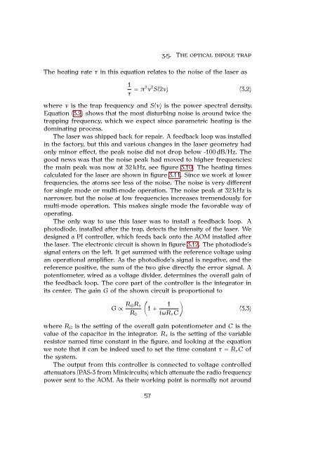
The heating rate τ in this equation re<strong>la</strong>tes to the noise of the <strong>la</strong>ser as<br />
1<br />
τ = π2 ν 2 S(2ν) (3.2)<br />
where ν is the trap frequency and S(ν) is the power spectral <strong>de</strong>nsity.<br />
Equation (3.2) shows that the most disturbing noise is around twice the<br />
trapping frequency, which we expect since parametric heating is the<br />
dominating process.<br />
The <strong>la</strong>ser was shipped back for repair. A feedback loop was installed<br />
in the factory, but this and various changes in the <strong>la</strong>ser geometry had<br />
only minor effect, the peak noise did not drop below -100 dB/Hz. The<br />
good news was that the noise peak had moved to higher frequencies:<br />
the main peak was now at 32 kHz, see figure 3.10. The heating times<br />
calcu<strong>la</strong>ted for the <strong>la</strong>ser are shown in figure 3.11. Since we work at lower<br />
frequencies, the atoms see less of the noise. The noise is very different<br />
for single mo<strong>de</strong> or multi-mo<strong>de</strong> operation. The noise peak at 32 kHz is<br />
narrower, but the noise at low frequencies increases tremendously for<br />
multi-mo<strong>de</strong> operation. This makes single mo<strong>de</strong> the favorable way of<br />
operating.<br />
The only way to use this <strong>la</strong>ser was to install a feedback loop. A<br />
photodio<strong>de</strong>, installed after the trap, <strong>de</strong>tects the intensity of the <strong>la</strong>ser. We<br />
<strong>de</strong>signed a PI controller, which feeds back onto the AOM installed after<br />
the <strong>la</strong>ser. The electronic circuit is shown in figure 3.12. The photodio<strong>de</strong>’s<br />
signal enters on the left. It get summed with the reference voltage using<br />
an operational amplifier. As the photodio<strong>de</strong>’s signal is negative, and the<br />
reference positive, the sum of the two give directly the error signal. A<br />
potentiometer, wired as a voltage divi<strong>de</strong>r, <strong>de</strong>termines the overall gain of<br />
the feedback loop. The core part of the controller is the integrator in<br />
its center. The gain G of the shown circuit is proportional to<br />
G ∝ RGRτ<br />
R0<br />
� �<br />
1<br />
1 +<br />
iωRτC<br />
(3.3)<br />
where RG is the setting of the overall gain potentiometer and C is the<br />
value of the capacitor in the integrator. Rτ is the setting of the variable<br />
resistor named time constant in the figure, and looking at the equation<br />
we note that it can be in<strong>de</strong>ed used to set the time constant τ = RτC of<br />
the system.<br />
The output from this controller is connected to voltage controlled<br />
attenuators (PAS-3 from Minicircuits) which attenuate the radio frequency<br />
power sent to the AOM. As their working point is normally not around<br />
57


