

Martin Teichmann Atomes de lithium-6 ultra froids dans la ... - TEL
Martin Teichmann Atomes de lithium-6 ultra froids dans la ... - TEL
Martin Teichmann Atomes de lithium-6 ultra froids dans la ... - TEL

You also want an ePaper? Increase the reach of your titles
YUMPU automatically turns print PDFs into web optimized ePapers that Google loves.
CHAPTER 3. EXPERIMENTAL SETUP<br />
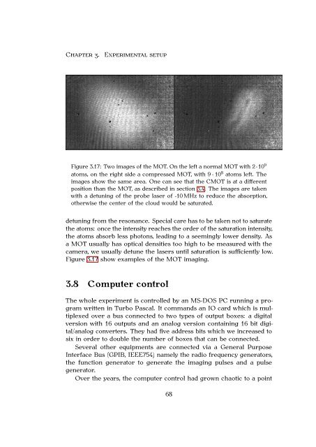
Figure 3.17: Two images of the MOT. On the left a normal MOT with 2·10 9<br />
atoms, on the right si<strong>de</strong> a compressed MOT, with 9 · 10 8 atoms left. The<br />
images show the same area. One can see that the CMOT is at a different<br />
position than the MOT, as <strong>de</strong>scribed in section 3.4. The images are taken<br />
with a <strong>de</strong>tuning of the probe <strong>la</strong>ser of -10 MHz to reduce the absorption,<br />
otherwise the center of the cloud would be saturated.<br />
<strong>de</strong>tuning from the resonance. Special care has to be taken not to saturate<br />
the atoms: once the intensity reaches the or<strong>de</strong>r of the saturation intensity,<br />
the atoms absorb less photons, leading to a seemingly lower <strong>de</strong>nsity. As<br />
a MOT usually has optical <strong>de</strong>nsities too high to be measured with the<br />
camera, we usually <strong>de</strong>tune the <strong>la</strong>sers until saturation is sufficiently low.<br />
Figure 3.17 show examples of the MOT imaging.<br />
3.8 Computer control<br />
The whole experiment is controlled by an MS-DOS PC running a program<br />
written in Turbo Pascal. It commands an IO card which is multiplexed<br />
over a bus connected to two types of output boxes: a digital<br />
version with 16 outputs and an analog version containing 16 bit digital/analog<br />
converters. They had five address bits which we increased to<br />
six in or<strong>de</strong>r to double the number of boxes that can be connected.<br />
Several other equipments are connected via a General Purpose<br />
Interface Bus (GPIB, IEEE754) namely the radio frequency generators,<br />
the function generator to generate the imaging pulses and a pulse<br />
generator.<br />
Over the years, the computer control had grown chaotic to a point<br />
68


