
You also want an ePaper? Increase the reach of your titles
YUMPU automatically turns print PDFs into web optimized ePapers that Google loves.
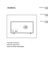
<strong>Service</strong> <strong>Manual</strong><br />
Infant Flow ® SiPAP<br />
Model M675<br />
© Copyright 2004, VIASYS Healthcare Critical Care<br />
675-120 Revision C November 2004
2 Infant Flow ® SiPAP<br />
675-120 Revision C November 2004
<strong>Service</strong> <strong>Manual</strong> 3<br />
Revision History<br />
Date Revision Pages Changes<br />
September 2003 675-120(1) All Release<br />
November 2004 B All Release manual in VIASYS Healthcare<br />
template using VIASYS Healthcare Critical<br />
Care nomenclature.<br />
December 2004 C Title page, 19,<br />
30, 39, 45, 50,<br />
56, 57, 61, 62,<br />
64, 65, 68, 69,<br />
73, 75, 81–83,<br />
86, 87, 88<br />
Revised per EO 27980.<br />
Removed the picture from the title page.<br />
Deleted the ESD warning from page 19.<br />
Removed “O2 Sensor” and added the word<br />
“measured” on page 30.<br />
Changed “O2 sensor” to “fuel cell” on<br />
pages 39, 45, 62, 68, 69, 73, 86, and 87.<br />
Replaced the O2 senor row on page 50.<br />
Updated the error codes on pages 56 and<br />
57.<br />
Replaced the warning on page 61.<br />
Changed the Fitting procedure on pages<br />
64, 68, and 75.<br />
Changed step 6 on page 65.<br />
Added Addendum A – Oxygen Leak Test<br />
Changed Transducer Assy. to Transducer<br />
Interface on page 88.<br />
675-120 Revision C November 2004
4 Infant Flow ® SiPAP<br />
Contact and Ordering Information<br />
United States, Latin America, Asia Pacific:<br />
Sales, <strong>Service</strong> and Clinical Support:<br />
VIASYS Healthcare<br />
Critical Care Division<br />
22705 Savi Ranch Parkway<br />
Yorba Linda, CA 92887<br />
Phone: (714) 283-8444<br />
(800) 381-3552<br />
Fax: (714) 283-8493<br />
www.VIASYShc.com<br />
United Kingdom:<br />
Sales, <strong>Service</strong> and Clinical Support:<br />
VIASYS Healthcare<br />
3 Welton Rd.<br />
Warwick,<br />
CV34 5PZ<br />
Phone: 01926 490888<br />
Fax: 01926 402262<br />
Europe<br />
Sales and Customer <strong>Service</strong> Technical <strong>Service</strong><br />
VIASYS Healthcare VIASYS Healthcare<br />
Critical Care Division Leibnizstrasse 7<br />
22705 Savi Ranch Parkway D-97204 Hoechburg<br />
Yorba Linda, CA 92887 Germany<br />
Phone: (714) 283-8444 Phone +49 (0) 931 4972 – 0<br />
(800) 381-3552 Fax:+49 (0) 931 4972 –423<br />
e-mail: Support.CC.EU@VIASYShc.com<br />
website: www.VIASYShc.com<br />
675-120 Revision C November 2004
<strong>Service</strong> <strong>Manual</strong> 5<br />
Warranty<br />
The Infant Flow ® SiPAP is warranted to be free from defects in material and<br />
workmanship and to meet the published specifications for One (1) year from date of<br />
shipment.<br />
The liability of VIASYS Healthcare, Critical Care Division, (referred to as the<br />
Company) under this warranty is limited to replacing, repairing or issuing credit, at<br />
the discretion of the Company, for parts that become defective or fail to meet<br />
published specifications during the warranty period; the Company will not be liable<br />
under this warranty unless (A) the Company is promptly notified in writing by Buyer<br />
upon discovery of defects or failure to meet published specifications; (B) the<br />
defective unit or part is returned to the Company, transportation charges prepaid by<br />
Buyer; (C) the defective unit or part is received by the Company for adjustment no<br />
later than four weeks following the last day of the warranty period; and (D) the<br />
Company’s examination of such unit or part shall disclose, to its satisfaction, that<br />
such defects or failures have not been caused by misuse, neglect, improper<br />
installation, unauthorized repair, alteration or accident.<br />
Any authorization of the Company for repair or alteration by the Buyer must be in<br />
writing to prevent voiding the warranty. In no event shall the Company be liable to<br />
the Buyer for loss of profits, loss of use, consequential damage or damages of any<br />
kind based upon a claim for breach of warranty, other than the purchase price of any<br />
defective product covered hereunder.<br />
The Company warranties as herein and above set forth shall not be enlarged,<br />
diminished or affected by, and no obligation or liability shall arise or grow out of the<br />
rendering of technical advice or service by the Company or its agents in connection<br />
with the Buyer's order of the products furnished hereunder.<br />
Limitation of Liabilities<br />
This warranty does not cover normal maintenance such as cleaning, adjustment or<br />
lubrication and updating of equipment parts. This warranty shall be void and shall not<br />
apply if the equipment is used with accessories or parts not manufactured by the<br />
Company or authorized for use in writing by the Company or if the equipment is not<br />
maintained in accordance with the prescribed schedule of maintenance.<br />
The warranty stated above shall extend for a period of One (1) year from date of<br />
shipment, with the following exceptions:<br />
1. Components for monitoring of physical variables such as temperature,<br />
pressure, or flow are warranted for ninety (90) days from date of receipt.<br />
2. Elastomeric components and other parts or components subject to<br />
deterioration, over which the Company has no control, are warranted for sixty<br />
(60) days from date of receipt.<br />
3. Internal batteries are warranted for ninety (90) days from the date of receipt.<br />
The foregoing is in lieu of any warranty, expressed or implied, including, without<br />
limitation, any warranty of merchantability, except as to title, and can be amended<br />
only in writing by a duly authorized representative of the Company.<br />
675-120 Revision C November 2004
6 Infant Flow ® SiPAP<br />
Contents<br />
Revision History.................................................................................... 3<br />
Contact and Ordering Information ...................................................... 4<br />
Warranty ................................................................................................ 5<br />
Limitation of Liabilities ................................................................................................... 5<br />
Contents ................................................................................................ 6<br />
Notices ................................................................................................... 8<br />
Copyright Notice ............................................................................................................ 8<br />
Trademark Notices ........................................................................................................ 8<br />
EMC Notice ................................................................................................................... 8<br />
MRI Notice..................................................................................................................... 9<br />
Intended Use Notice ...................................................................................................... 9<br />
Regulatory Notice .......................................................................................................... 9<br />
Classification ................................................................................................................. 9<br />
Declaration of Conformity Notice................................................................................. 10<br />
Chapter 1 - Product Description ........................................................ 12<br />
Infant Flow ® SiPAP Features .............................................................. 12<br />
Chapter 2 - Product Specifications ................................................... 14<br />
Modes.......................................................................................................................... 14<br />
Controls ....................................................................................................................... 14<br />
Monitors....................................................................................................................... 14<br />
Alarms ......................................................................................................................... 15<br />
Pneumatic Supply........................................................................................................ 15<br />
Electrical Supply .......................................................................................................... 15<br />
Atmospheric & Environmental ..................................................................................... 16<br />
Physical ....................................................................................................................... 16<br />
Chapter 3: Summary of Warnings and Cautions ............................. 18<br />
Terms ................................................................................................... 18<br />
Warnings ..................................................................................................................... 18<br />
Cautions ...................................................................................................................... 20<br />
Chapter 4: System Construction ....................................................... 22<br />
Touch Screen .............................................................................................................. 26<br />
Alarm Conditions ......................................................................................................... 27<br />
Diagnostic Screen ....................................................................................................... 28<br />
Chapter 5 - Operation ......................................................................... 30<br />
Gas Flow ..................................................................................................................... 30<br />
Electronic Functions .................................................................................................... 32<br />
Electrical Layout .......................................................................................................... 33<br />
Fault Management....................................................................................................... 34<br />
Chapter 6 - Operation ......................................................................... 36<br />
675-120 Revision C November 2004
<strong>Service</strong> <strong>Manual</strong> 7<br />
Preparing and Connecting the Equipment................................................................... 36<br />
Setting Up the Equipment............................................................................................ 40<br />
Setting the NCPAP Parameters................................................................................... 41<br />
Setting the BiPhasic Parameters ................................................................................. 42<br />
Setting the Triggered BiPhasic Parameters................................................................. 43<br />
Calibration....................................................................................................................44<br />
Giving a <strong>Manual</strong> Timed Sigh........................................................................................ 45<br />
Operation Without Electrical Power ............................................................................. 45<br />
Fault Indications........................................................................................................... 45<br />
Diagnostics .................................................................................................................. 52<br />
Chapter 7- Maintenance ...................................................................... 60<br />
Cleaning ............................................................................................... 60<br />
Maintenance......................................................................................... 60<br />
General........................................................................................................................60<br />
Maintenance Frequencies ........................................................................................... 61<br />
Removal and Fitting of Case ....................................................................................... 62<br />
Removal and Fitting of Battery .................................................................................... 62<br />
Removal and Fitting of Oxygen Filter .......................................................................... 65<br />
Removal and Fitting of Fuel Cell Filter/Restrictor ........................................................ 66<br />
Removal and Fitting of the Fuel Cell............................................................................ 67<br />
Removal and Fitting of Blender and Components....................................................... 68<br />
Removal and Fitting of Water Trap Filter..................................................................... 71<br />
Removal and Fitting of Case Bleed Filtered Restrictor................................................ 72<br />
Removal and Fitting of PA Solenoid Valve .................................................................. 73<br />
Firmware Reload/Upgrade........................................................................................... 73<br />
Testing.........................................................................................................................74<br />
Chapter 8 – Explanation of Symbols ................................................. 75<br />
Symbols used on buttons................................................................... 77<br />
Appendix A- Oxygen Leak Test.......................................................... 79<br />
Appendix B- Product Configurations ................................................ 82<br />
Non-US Configuration Parameters ..................................................... 82<br />
US Configuration Parameters ................................................................ 82<br />
Appendix C - Spare Parts ................................................................. 83<br />
Additional <strong>Service</strong> Parts ..................................................................... 84<br />
Glossary ............................................................................................... 87<br />
675-120 Revision C November 2004
8 Infant Flow ® SiPAP<br />
Notices<br />
Copyright Notice<br />
Copyright © 2004 VIASYS Healthcare, Critical Care Division, California.<br />
This work is protected under Title 17 of the U.S. Code and is the sole property of the<br />
Company. No part of this document may be copied or otherwise reproduced, or<br />
stored in any electronic information retrieval system, except as specifically permitted<br />
under U.S. Copyright law, without the prior written consent of the Company. For<br />
more information, contact:<br />
World Headquarters European Office<br />
1100 Bird Center Drive Rembrandtlaan 1b<br />
Palm Springs, CA 92262-8099 3723 BG Bilthoven<br />
U.S.A. P.O. Box 299, 3720 AG Bilthoven<br />
Phone: (760) 778-7200 The Netherlands<br />
(800) 328-4139 Phone: +31 (30) 2289 711<br />
Fax: (760) 778-7274 Fax: +31 (30) 2286 244<br />
www.VIASYSCriticalCare.com<br />
Trademark Notices<br />
Infant Flow ® and SiPAP are trademarks of VIASYS Healthcare, Critical Care Division<br />
in the U.S. and some other countries. All other brand names and product names<br />
mentioned in this manual are trademarks, registered trademarks, or trade names of<br />
their respective holders.<br />
EMC Notice<br />
This equipment radiates and is susceptible to radio frequency energy. If not installed<br />
and used in accordance with the instructions in this manual, electromagnetic<br />
interference may result. The equipment has been tested and found to comply with<br />
the limits set forth in BS EN60601-1-2 for Medical Electrical Equipment Part 1-2:<br />
General requirements for safety-collateral standard. Electromagnetic compatibility –<br />
requirements and tests. These limits provide reasonable protection against<br />
electromagnetic interference when operated in the intended use environments (e.g.<br />
hospitals) described in this manual.<br />
This device is also designed and manufactured to comply with the following<br />
standards;<br />
Safety: UL 60601-1: 2003 Medical Electrical Equipment, Part 1: General<br />
Requirements for Safety.<br />
CAN/CSA C22.2 No 601.1-M90, Medical Electrical Equipment - Part<br />
1: General Requirements for Safety including C22.2 No. 601.1S1-94<br />
(IEC601-1, Amendment 1:1991) Supplement No. 1-94 to CAN/CSA<br />
22.2 No. 601.1-M90<br />
675-120 Revision C November 2004
<strong>Service</strong> <strong>Manual</strong> 9<br />
With regards to Electrical Safety:<br />
Class 1 equipment<br />
Contains type BF patient applied parts<br />
Continuous Operation<br />
MRI Notice<br />
This equipment contains electromagnetic components whose operation can be<br />
affected by intense electromagnetic fields.<br />
Do not operate this device in a MRI environment or in the vicinity of high-frequency<br />
surgical diathermy equipment, defibrillators, or short-wave therapy equipment.<br />
Electromagnetic interference could disrupt the operation of the device.<br />
Intended Use Notice<br />
The Infant Flow ® SiPAP, consisting of a Driver and Generator plus NCPAP Prongs<br />
and Masks, is a medical device intended for the provision of Bi-Level CPAP to<br />
produce a sigh. This system is for use in Hospital, Hospital Type facilities and intra-<br />
Hospital transport environments and is indicated for the treatment of Newborn and<br />
Infant patients.<br />
Operators of this equipment and <strong>Service</strong> Engineers are required to read and thoroughly<br />
understand the contents of this manual before using or maintaining the equipment.<br />
This manual is intended for use by a competent, fully qualified <strong>Service</strong><br />
Engineer. It includes a description of the unit and how it works. It also contains<br />
operating and diagnostic procedures and maintenance instructions. For usage<br />
of associated equipment, refer to the Manufacturer’s literature.<br />
Regulatory Notice<br />
Federal law restricts the sale of this device except by or on order of a physician.<br />
Classification<br />
Type of Equipment: Medical Equipment, Class 1 and internally powered, IPX1<br />
Protected, and uses type BF applied parts. Equipment is not suitable for use in<br />
presence of flammable anesthetics.<br />
675-120 Revision C November 2004
10 Infant Flow ® SiPAP<br />
Declaration of Conformity Notice<br />
This medical equipment complies with the Medical Device Directive, 93/42/EEC, and<br />
the following Technical Standards, to which Conformity is declared:<br />
Council Directive(s): MDD 93/42/EEC Annex II (excluding section 4)<br />
Safety: EN 60601-1, EN 794-1<br />
EMC: EN 60601-1-2:2001<br />
Conformity Assessment: MDD Annex II<br />
Quality System: ISO 13485<br />
EU Notified Body: BSI (Reg. No. 0086)<br />
Device Classification: IIb<br />
EU Notified Body:<br />
BSI (Reg. No. 0086)<br />
Trade names:<br />
Infant Flow SiPAP<br />
Manufactured by:<br />
SensorMedics Corporation<br />
22705 Savi Ranch Parkway<br />
Yorba Linda, CA 92887, USA<br />
If you have a question regarding the Declaration of Conformity for this product,<br />
please contact VIASYS Healthcare, Critical Care Division.<br />
675-120 Revision C November 2004
<strong>Service</strong> <strong>Manual</strong> 11<br />
675-120 Revision C November 2004
12 Infant Flow ® SiPAP<br />
Chapter 1 - Product Description<br />
The Infant Flow ® SiPAP is a non-invasive form of respiratory support designed for<br />
use in hospital environments such as Neonatal and Pediatric Intensive Care Units. It<br />
can also be used when transporting patients within the hospital environment.<br />
The Infant Flow ® SiPAP is currently available in a Plus or Comprehensive<br />
configuration. The Plus configuration provides NCPAP and time triggered, BiPhasic<br />
modes with and without breath rate monitoring. The Comprehensive configuration<br />
offers these features plus patient BiPhasic mode with apnea backup breaths. The<br />
Infant Flow ® SiPAP comes standard in all configurations with an LCD touch screen<br />
display, pressure time waveform graphics, integrated patient monitoring, alarms for<br />
high and low pressure and FiO2 and up to 2 hours of backup battery power.<br />
As a result of the unique patented design, the Infant Flow ® SiPAP has been proven<br />
to provide the most stable CPAP at the lowest work of breathing for patients<br />
compared to other devices. The outstanding performance of the Infant Flow ® SiPAP<br />
is irrespective of patient demand or expiratory flows. This system has been designed<br />
and tested to perform optimally when used only with accessories available from<br />
VIASYS Healthcare, Inc. These accessories include circuits and generators, prong<br />
and mask patient interfaces and bonnets.<br />
Infant Flow ® SiPAP Features<br />
The expanded capabilities of the Infant Flow ® SiPAP Plus and Comprehensive<br />
configurations allow for applications to broader range of patients who may otherwise<br />
not be candidates for non-invasive respiratory support.<br />
NCPAP – allows for continuous positive airway pressure based on clinician set<br />
pressure. Breath rate monitoring/alarm can be activated in this mode.<br />
BiPhasic - allows for time triggered pressure assists to be delivered based on<br />
clinician set inspiratory time, rate, and pressure criteria. Breath rate monitoring/alarm<br />
can be activated in this mode.<br />
BiPhasic tr* - allows for patient triggered pressure assists to be delivered based on<br />
clinician set inspiratory time and pressure criteria. Breath rate monitoring/alarm, and<br />
Apnea backup breaths are automatically active in the mode.<br />
Patented Infant Flow ® Generator - The Infant Flow ® Generator is a fluidic device for<br />
the generation of consistent infant nasal CPAP with a low work of breathing<br />
compared to other devices.<br />
Fully integrated alarms packages – . Supply gases failure, High Patient Pressure,<br />
Low patient pressure, high and low delivered Oxygen concentration, change from AC<br />
to DC power source, low and flat battery charge status and Low breath rate/apnea<br />
alarm.<br />
Battery Backup – Up to 2 hours of battery backup allows for intra-hospital transport.<br />
Clear indicators are provided for power supply in use (AC or DC), and battery charge<br />
level.<br />
675-120 Revision C November 2004
<strong>Service</strong> <strong>Manual</strong> 13<br />
Screen Lock - After 120 seconds of no screen inputs, the screen changes to the<br />
Locked Screen to prevent inadvertent changes. Upon activation of a high priority<br />
alarm the screen changes to an unlocked state to allow for immediate interventions<br />
as required.<br />
Table 1 – Functions and Accessories<br />
Functions & Accessories Plus Comprehensive*<br />
NCPAP • •<br />
NCPAP with breath rate monitoring<br />
and alarm<br />
• •<br />
BiPhasic • •<br />
BiPhasic with breath rate monitoring<br />
and alarm<br />
• •<br />
BiPhasic tr* •<br />
Internal Battery • •<br />
<strong>Manual</strong> Breath • •<br />
Apnea Back up rate •<br />
Screen lock • •<br />
Prioritization of alarms • •<br />
*Comprehensive configuration not available for sale in the United States<br />
CAUTION<br />
The Infant Flow SiPAP has been designed and tested as a complete system using<br />
Infant Flow accessories. Only accessories approved for use should be used. If in<br />
doubt, please contact your local VIASYS representative.<br />
675-120 Revision C November 2004
14 Infant Flow ® SiPAP<br />
Chapter 2 - Product Specifications<br />
Modes<br />
Controls<br />
Monitors<br />
• NCPAP<br />
• NCPAP with breath rate monitoring and low rate alarm<br />
• BiPhasic (time triggered)<br />
• BiPhasic (time triggered) with breath rate monitoring and low rate alarm<br />
• BiPhasic tr (patient triggered ) with breath rate monitoring, low breath rate<br />
alarm, and apnea back up<br />
• Inspiratory Time (Ti) – 0.1-3.0 seconds<br />
• Rate (R) – 1-120 (Comprehensive* only)<br />
• Rate (R) – 1-54 (Plus only)<br />
• Apnea Interval (Tapnea) – 10-30 seconds, 5 second intervals (Comp* only)<br />
• Apnea Interval (TLBR) – 10-30 seconds, 5 second intervals (Plus only)<br />
• NCPAP/Pres Low flow meter – 0-15L/min, accuracy +/- 15% of selected<br />
output<br />
• NCPAP/Pres High flow meter – 0-5L/min, accuracy +/- 15% of selected<br />
output<br />
• <strong>Manual</strong> Breath – X 1<br />
• Rate monitoring on/off – NCPAP<br />
• %O2 – 21 - 100% - accuracy +/-3%<br />
• CPAP<br />
• PEEP<br />
• MAP<br />
• PIP<br />
• %O2<br />
• I:E ratio<br />
• Spontaneous rate (Rs)<br />
• Battery charge level<br />
675-120 Revision C November 2004
<strong>Service</strong> <strong>Manual</strong> 15<br />
Alarms<br />
• High airway pressure – 3 cmH20 above measured airway pressure<br />
• High circuit pressure – maximum 11 cmH20 in time triggered Biphasic mode<br />
• High circuit pressure – maximum 15 cmH20 in patient triggered Biphasic tr*<br />
mode<br />
• Low airway pressure – 2 cmH20 below measured airway pressure or 1<br />
cmH20 if otherwise would be zero<br />
• High and Low delivered Oxygen concentration +5% of setting<br />
• Low breath rate alarm<br />
• Low or Flat battery charge level<br />
• Input gases failure<br />
• Alarm volume (electronic alarms) 70 dBa at 1 meter<br />
Pneumatic Supply<br />
• Patient Gas Outlet - 15 mm standard taper fitting<br />
• Patient Pressure Input - 4.5 mm Luer taper fitting<br />
• Gas Supply - Nominal 4 bar, clean, dry medical air and oxygen<br />
• Range - 2.8 - 6 bar; Maximum differential pressure 2 bar<br />
• Manometer - Range 0 to + 20 cmH2O, accuracy, ± 2% of span<br />
• Gas Connections - Standard DISS or NIST connectors<br />
Electrical Supply<br />
• Input Voltage -100-230 VAC<br />
• Input Frequency -50/60 Hz<br />
• Power Consumption -50 VA maximum<br />
• Fuse Rating For 220 V nominal operation-“T” Type 2.5 A at 250 V<br />
• Device Housing Protection rating level -IPX1<br />
• Battery Working Time -2 hours (from fully charged state)<br />
• Battery Charging Time –max. 16 hours<br />
675-120 Revision C November 2004
16 Infant Flow ® SiPAP<br />
Atmospheric & Environmental<br />
Physical<br />
• Temperature Range-Operating: 5 – 40° C<br />
• Storage: 0 - 50° C<br />
• Relative Humidity -Operating: 0 – 90% non-condensing<br />
• Storage: 0 – 90% non-condensing<br />
• Dimensions (driver only)-(W x H x D) 26 x38 x 23.5 cm /<br />
10.25 x15 x 9.25 in<br />
• Weight (driver only)-8.8 kg / 19.5 lb<br />
675-120 Revision C November 2004
<strong>Service</strong> <strong>Manual</strong> 17<br />
675-120 Revision C November 2004
18 Infant Flow ® SiPAP<br />
Chapter 3: Summary of Warnings and<br />
Cautions<br />
Terms<br />
Please review the following safety information prior to operating the Infant Flow ®<br />
SiPAP. Attempting to operate this equipment without fully understanding its features<br />
and functions may result in unsafe operating conditions.<br />
Warnings and Cautions, which are general to the use of the device under all<br />
circumstances, are included in this section. Some Warnings and Cautions are also<br />
inserted within the manual where they are most meaningful.<br />
Notes are also located throughout the manual to provide additional information<br />
related to specific features.<br />
If you have a question regarding the installation, set up, operation, or maintenance of<br />
the device, contact VIASYS Healthcare Customer Care.<br />
WARNINGS identify conditions or practices that could result in serious adverse<br />
reactions or potential safety hazards.<br />
CAUTIONS identify conditions or practices that could result in damage to the<br />
ventilator or other equipment.<br />
NOTES identify supplemental information to help you better understand how<br />
the ventilator works.<br />
Warnings<br />
• Whenever a patient is attached to respiratory care equipment, constant<br />
attendance is required by qualified personnel. The use of an alarm or<br />
monitoring system does not give absolute assurance of warning for every<br />
malfunction that may occur in the system. In addition, some problems may<br />
require immediate attention.<br />
• The gas blender incorporated in this product is designed to mix medical<br />
grade air and oxygen only. Do not modify the inlets to accommodate other<br />
source gases such as anesthetic gases.<br />
• Check that the water trap is empty before use and empty it frequently during<br />
use.<br />
• Liquid water or other contaminants in either gas supply, particularly the air<br />
supply, may cause malfunction of this equipment and equipment connected<br />
to it.<br />
675-120 Revision C November 2004
<strong>Service</strong> <strong>Manual</strong> 19<br />
• When filling a humidifier, do not move the stand. Moving or transporting the<br />
stand while refilling may cause the stand and equipment to over balance.<br />
• Do not use conductive patient circuits with the Infant Flow SiPAP Driver.<br />
• Nasal CPAP can cause nasal irritation, septal distortion, skin irritation and<br />
pressure necrosis. Observe the usage guidelines to minimize these<br />
complications.<br />
• This device exhausts O2 during normal operation. Oxygen vigorously<br />
accelerates combustion. To avoid fire hazard, do not place flammable<br />
materials or sources of heat close to the exhaust.<br />
• Do not use the equipment without the exhaust tube fitted (refer to Figure 2).<br />
• To reduce trip hazard, always ensure cable and tubes are restrained away<br />
from walking areas.<br />
• The Abdominal Respiratory Sensor will not detect all forms of apnea.<br />
Independent monitoring should always be used with this device.<br />
• If the unit is shelf mounted, ensure that the unit is stable and that hoses and<br />
cables are restrained to avoid hazard of toppling.<br />
• This equipment is not suitable for use in the presence of a flammable<br />
anesthetic mixture.<br />
• The NCPAP Pres High flowmeter must be adjusted to zero when not required<br />
for the patient.<br />
• Under extreme conditions (minimum supply pressure and maximum gas<br />
demand, including auxiliary output) output flow rates and delivered pressure<br />
may be reduced.<br />
• Only use the supplied AC cable to connect to the power supply.<br />
• Do not attach the Generator to the patient until the initial set up is complete.<br />
• The indicates a connection between the transducer interface and the<br />
unit. It does not indicate correct positioning of the Abdominal Respiratory<br />
Sensor.<br />
• Calibration must only be done when the unit is not connected to the patient.<br />
• Ensure the whistle sounds during gas connection. If not, the device may be<br />
faulty and should not be used. Refer to your <strong>Service</strong> Engineer.<br />
• Verify that the displayed value for delivered FiO2 corresponds to the value set<br />
on the blender. Refer to Faults and Indications.<br />
• Oxygen vigorously accelerates combustion. To avoid explosion hazard, do<br />
not use any instrument or other equipment that may have been exposed to oil<br />
or grease contamination.<br />
675-120 Revision C November 2004
20 Infant Flow ® SiPAP<br />
Cautions<br />
• Federal Law (USA) restricts this device to sale by or on the order of a<br />
physician.<br />
• The precision gas blender in this product may become non-functional or<br />
damaged if used without the protective water trap and filters provided.<br />
• The power switch on this unit does not isolate the external power supply.<br />
Disconnect the power supply cable to ensure complete isolation.<br />
• Before use, verify that this equipment has been authorized for use by a<br />
qualified person.<br />
• The Infant Flow SiPAP has been designed and tested as a complete<br />
system using Infant Flow accessories. Only accessories approved for use<br />
should be used. If in doubt, please contact your local VIASYS representative.<br />
• Where the integrity of the external protective earth conductor is in doubt, the<br />
equipment shall be powered by its internal power source (battery).<br />
• Do not immerse any part of the IFSD in water or sterilize it with gas or steam.<br />
• Ensure patient breathing circuit is replaced at regular intervals.<br />
675-120 Revision C November 2004
<strong>Service</strong> <strong>Manual</strong> 21<br />
675-120 Revision C November 2004
22 Infant Flow ® SiPAP<br />
Chapter 4: System Construction<br />
CAUTION<br />
Where the integrity of the external protective earth conductor is in doubt the<br />
equipment shall be powered by its internal power source (battery).<br />
The IFSD is AC powered with an integral rechargeable DC battery that provides<br />
power for up to two hours without any interruption of performance or function. If the<br />
AC power supply fails or is disconnected, the IFSD automatically switches to battery<br />
power and gives an audio and visual alarm.<br />
The IFSD is enclosed in a case with Operator controls and input connectors on the<br />
front and rear panel. The front panel is shown in Figure 1. The back panel is shown<br />
in Figure 2. The case incorporates non slip feet for table top use or must be fitted to<br />
a dedicated stand. The major components within the casing are:<br />
• a gas module<br />
• an electronics module<br />
• a front panel module<br />
• a patient trigger module<br />
• a firmware module<br />
675-120 Revision C November 2004
<strong>Service</strong> <strong>Manual</strong> 23<br />
Gas Module<br />
Figure 1 - IFSD Front Panel<br />
The function of the gas module is to take air and oxygen, blend them into the<br />
required mixture and deliver this mixture to the patient at the prescribed flow rate.<br />
The gas module also measures the oxygen concentration, measures the patient<br />
pressure, provides an auxiliary gas outlet (optional) and provides switched Biphasic flow.<br />
The main components are an air/oxygen blender, a flow manifold, a vent valve, an<br />
exhaust manifold with alarm whistle, NCPAP Pres low and NCPAP Pres high flowmeters,<br />
and a valve/sensor PCB. The inlet gas connections are on an interchangeable inlet block<br />
to allow for different gas fittings. The exhaust manifold discharges gas to the outside of<br />
the case and is positioned away from the electrical connectors and switch to reduce any<br />
potential explosive hazard.<br />
675-120 Revision C November 2004
24 Infant Flow ® SiPAP<br />
Electronics Module<br />
The function of the electronics module is to power the unit either by AC mains supply<br />
or DC emergency battery supply, to control the gas module and read the gas module<br />
sensors. The main components are a power supply unit, a rechargeable battery, a<br />
main processor PCB, LED PCB, Valve/Sensor PCB and a LCD screen (touch<br />
screen). The LCD screen includes a back-light which is always on when the IFSD is<br />
powered. The touch screen displays information and receives inputs from the Operator<br />
via the touch screen keyboard.<br />
Figure 2 - IFSD Back Panel<br />
Ground test<br />
point<br />
675-120 Revision C November 2004
<strong>Service</strong> <strong>Manual</strong> 25<br />
Figure 3 -IFSD Internal Components<br />
675-120 Revision C November 2004
26 Infant Flow ® SiPAP<br />
Front Panel Module<br />
The function of the front panel module is to house the gas and electrical connections<br />
to the patient, Operator controls and indicators. The module consists of a front panel<br />
plate, the touch screen with key pad, flowmeters and FiO2 control, patient connectors<br />
and indicators and an ambient light sensor. The backlight on the touch screen is<br />
decreased if the ambient light sensor detects a low ambient light level and increased<br />
if it detects a high ambient light level.<br />
The green Power light is always on when AC power is connected to the unit.<br />
The Alarm Warning Bar flashes red to indicate an alarm.<br />
Patient Trigger Module (Plus and Comprehensive Models)<br />
The patient trigger module consists of a PCB which plugs into the main processor<br />
PCB. Its function is to detect patient breaths and apnea and give this information to the<br />
main processor in the electronics module. The main processor uses the signals from the<br />
patient trigger module to instruct the biphasic pressure control to provide a timed sigh<br />
to the patient.<br />
Firmware Module<br />
The firmware module is the unit’s embedded software. Its function is to instruct the<br />
microprocessor how to control the unit and to interact with the Operator.<br />
Touch Screen<br />
The touch screen provides the Operator with a series of screens with icons to enable<br />
settings, calibration and fault diagnosis. The Start Up Screen is shown in Figure 4.<br />
The display includes a status bar which incorporates a battery status, mode<br />
indicator, alarm button and patient trigger indicator. The center part of the display<br />
shows icons which relate to the function being selected or performed. The display also<br />
includes a key pad with six keys. The icon in each key changes depending on the<br />
function being performed.<br />
Battery Status and Charging Indicator<br />
If the battery status shows three bars or less, the display flashes alternately between<br />
red bars on a white background and a pink background.<br />
Alarm Button<br />
The alarm button alerts the Operator to fault conditions. An audible alarm is activated<br />
at the same time. In the unalarmed condition the button is green . In the<br />
high-priority alarm condition, the button flashes red and an audible<br />
alarm is heard. If the alarm button is pressed (to silence the audible alarm), the<br />
button changes to and flashes red. In a medium-priority alarm condition,<br />
the button flashes yellow and an audible alarm is heard. In a low-priority<br />
675-120 Revision C November 2004
<strong>Service</strong> <strong>Manual</strong> 27<br />
alarm condition, the button is solid yellow with an audible alarm. If any<br />
alarm condition resets itself, the yellow alarm bar remains to alert the clinician of a<br />
previous problem.<br />
Caution/Information<br />
The Caution/Information icon alerts the Operator to read this manual. It flashes<br />
during an alarm condition.<br />
Mode Indicator<br />
The Mode Indicator shows four question marks when in Start up or Adjust and<br />
changes to show the applicable mode in use (e.g. NCPAP).<br />
Figure 4 - Touch Screen Display – Start Up<br />
Patient Trigger Indicator (Plus and Comprehensive Models)<br />
The Patient Trigger indicator changes to when the transducer interface is<br />
connected and ready to be connected to the patient and indicates a when the<br />
transducer interface is not connected.<br />
Alarm Conditions<br />
Audible and visible alarm indications are given to alert the Operator to specified<br />
conditions that affect the operation of the unit. The electronic alarm limits are<br />
automatically set after two minutes without Operator inputs but the Operator can<br />
manually set the alarm parameters for certain conditions if required. The IFSD has<br />
the following alarms:<br />
675-120 Revision C November 2004
28 Infant Flow ® SiPAP<br />
• an audible Whistle which sounds a constant tone when the gas imbalance<br />
limits are exceeded.<br />
• an audible Alarm which sounds a constant tone or two different intermittent<br />
tones; medium or high level (medium level sounds beep.beep.beep every 15<br />
seconds and high level sounds beep.beep..beep beep beep every 10 seconds).<br />
• a visual Warning Bar which flashes red continuously, flashes intermittently or<br />
comes on continuously.<br />
• an Alarm Button on the touch screen status bar which flashes continuously.<br />
Other indications are given to indicate the status of the condition. Refer to Table 2 for<br />
alarms and indications for specified conditions.<br />
Diagnostic Screen<br />
A diagnostic screen is provided for low level calibration, test procedures for valves<br />
and an error log. Figure 5 shows the screen display. Labeling of Diagnostic screen<br />
will be the same regardless of configuration.<br />
Figure 5 - Diagnostic Screen<br />
675-120 Revision C November 2004<br />
-
<strong>Service</strong> <strong>Manual</strong> 29<br />
Table 2 – Diagnostic Screen Boxes<br />
Box Description<br />
DIPS The DIPS box shows the position of the DIP switches on the main processor<br />
PCB. Position 1 is on and O is off.<br />
CONTRAST<br />
INDICATOR<br />
CALIBRATION<br />
INDICATOR<br />
The contrast indicator box is for use in the factory for setting the screen<br />
contrast.<br />
The calibration indicator box shows during calibration, a when<br />
successfully completed and a if the calibration fails.<br />
The following display boxes show if the values are within the set parameters, a<br />
if the values are outside the set parameters, a if the function is not<br />
calibrated and a if the function is disabled on the DIP switch.<br />
Table 3 – Additional Diagnostic Screen Boxes<br />
Box Description<br />
S/W The S/W box shows the version and serial number of the loaded firmware.<br />
H/W The H/W box shows the status of the watchdog timer (WDG) and the EEPROM<br />
(E 2 P).<br />
PT The PT box shows the status of the Patient Trigger module.<br />
LCD The LCD box shows the ambient light sensor voltage (AMB), the back light level<br />
(BLL) and if the backlight is operative (BLF - 1 for fail, O for on).<br />
PSU The PSU box shows the external power supply voltage (EXT), the battery voltage<br />
(BAT), the battery charge status (CHG) and the temperature (TMP).<br />
RAILS The RAILS box shows the ground voltage (GRD), and the control voltages (6.5,<br />
8.2 and 10 V).<br />
RS232 The RS232 box shows factory set data.<br />
PRESSURE The PRESSURE box shows cm H2O pressure value, the voltage from the<br />
pressure sensor (PSEN) and the software offset (OFFS) and gain (GAIN)<br />
values.<br />
FLOW The FLOW box shows the flow rate (LPM), the voltage from the flow sensor<br />
(FSEN) and the software offset (OFFS) and gain (GAI N) values.<br />
ZVALVE The ZVALVE box shows if the Z DRIVE is operative (ZDRV - 1 for fail, O for on)<br />
for the zero valve and the Z sensor (ZSEN) voltage.<br />
DVALVE The DVALVE box shows if the D DRIVE is operative (DDRV - 1 for fail, O for on)<br />
for the dump valve and the D sensor (DSEN) voltage.<br />
PVALVE The PVALVE box shows if the P DRIVE is operative (PDRV - 1 for fail, O for on)<br />
for the pressure assist valve and the P sensor (PSEN) voltage.<br />
675-120 Revision C November 2004
30 Infant Flow ® SiPAP<br />
Chapter 5 - Operation<br />
Gas Flow<br />
With the oxygen and air connections connected and the power switched on, oxygen<br />
and air at 386 kPa (56 psig) flows to the blender. The air passes through a water trap<br />
with an integral filter where any moisture in the air is removed. Oxygen and air are<br />
filtered before entering a non-return valve in the blender. The blender mixes the<br />
oxygen and air in the proportion set by the position of the FiO2 control valve. The<br />
blender supplies blended gas between 2.5 and 30 L/min.<br />
The blender incorporates an alarm/bypass module. If a single gas supply fails or<br />
there is an imbalance between the inlet gas pressures exceeding 200 kPa (30 psig),<br />
the module directs the flow through a reed whistle to warn the Operator of the<br />
condition and at the same time connects the inlet gas at the higher pressure to the<br />
blender outlet.<br />
The blended gas is filtered before passing through a flow control to an oxygen<br />
analyzer. The oxygen analyzer utilizes a galvanic fuel cell to measure and display<br />
the measured delivered oxygen concentration.<br />
A vent valve on the exhaust manifold incorporates a solenoid operated pilot valve<br />
and a large orifice spool valve. The vent valve is normally held in the open position<br />
by a spring to vent high flow rates with low pressure drops so that the patient<br />
pressure is minimal. The electrically actuated pilot valve is operated by blended gas<br />
so that the vent valve continues to operate if one gas supply is lost.<br />
Blended gas flows through an electronically operated dump valve which is normally<br />
in the closed position. If over pressurization occurs, the sensors detect the condition<br />
and the controller signals the dump valve to open, sounds an alarm buzzer and at<br />
the same time closes the vent valve to rapidly reduce the patient pressure to near<br />
zero. When the over pressure condition stops, the controller signals the vent valve to<br />
open and the dump valve to close.<br />
The NCPAP flowmeter is set by the Operator to the required flow. The flow rate is<br />
shown on the gauge on the flowmeter. When the flowmeter control knob is turned<br />
fully clockwise, the flow of gas is turned off.<br />
675-120 Revision C November 2004
<strong>Service</strong> <strong>Manual</strong> 31<br />
Figure 6 - IFSD Gas Flow Schematic<br />
The patient pressure is shown on the touch screen and is monitored by a pressure<br />
sensor which sends the signal to the main processor. A zeroing valve automatically<br />
checks the pressure readings against atmospheric pressure to ensure accuracy of<br />
the patient pressure readings.<br />
A mechanical pop-off valve is factory set to limit the delivered pressure to a safe<br />
level sufficient to achieve the maximum required patient pressure at the generator.<br />
Adjustment of the pop-off valve is not required by Operators.<br />
Auxiliary Output (Optional)<br />
Blended gas flows through a fixed flow control and non-return valve to a standard<br />
DISS fitting on the back panel to supply a maximum 15 L/min for delivery to the<br />
patient via other sources.<br />
Inspiratory Pressure<br />
Blended gas passes through a variable outlet flow control and through the NCPAP<br />
Pres high flowmeter. The NCPAP Pres high flowmeter is set by the Operator to the<br />
required flow. The outlet from the NCPAP Pres high flowmeter when not delivering to<br />
the patient flows through a restrictor to exhaust, allowing the flowmeter to be<br />
adjusted without delivering gas to the patient. The flow rate is shown on the gauge<br />
on the flowmeter. When the flowmeter control knob is turned fully clockwise, the flow<br />
of gas is turned off. The flow is directed to the patient via a high speed selector valve<br />
which operates when requested by the NCPAP Pres high timing.<br />
675-120 Revision C November 2004
32 Infant Flow ® SiPAP<br />
WARNING<br />
The NCPAP Pres high must be adjusted to zero when not required for the<br />
patient.<br />
Triggered BiPhasic<br />
For BiPhasic Tr, a micro controller provides reliable indications of breaths derived<br />
from the patient abdominal respiratory sensor. It sends signals to operate the<br />
NCPAP Pres high valve to provide a timed sigh.<br />
WARNING<br />
Under extreme conditions (minimum supply pressure and maximum gas<br />
demand, including auxiliary output) output flow rates may reduce.<br />
Operation Without Electrical Power<br />
The IFSD can be used without electrical power. In this mode, NCPAP Pres low flow<br />
only is delivered, set by the NCPAP Pres low flowmeter and the required FiO2 level. In<br />
this mode, visual indications and warnings are not given except for the gas failure<br />
alarm.<br />
Electronic Functions<br />
Sensors mounted on the valve/sensor PCB monitor pressure, flow rate and oxygen.<br />
Sense signals for each of the valves allow the micro-controller to monitor the valve’s<br />
state and determine whether the valve is connected or short circuited. Current to the<br />
valve sensor PCB is limited via the fuses below a 10 VA limit to ensure safety in a<br />
possible oxygen enriched environment.<br />
The patient trigger PCB interfaces with the main processor PCB via a 20 way head.<br />
Communication between the two PCB’s is via a CAN bus. The main processor PCB<br />
also supplies +5 V power to this PCB and monitors other control signals.<br />
675-120 Revision C November 2004
<strong>Service</strong> <strong>Manual</strong> 33<br />
Electrical Layout<br />
Figure 7 - IFSD Electronic Enclosure<br />
Figure 8 shows the electrical wiring and PCB connector layout.<br />
Figure 8 - IFSD Electrical Wiring Diagram<br />
675-120 Revision C November 2004
34 Infant Flow ® SiPAP<br />
Fault Management<br />
When a software detectable fault condition occurs, the unit still allows a basic level of<br />
treatment to the patient. Table 4 shows the fault conditions and the level of control<br />
available.<br />
Table 4 - Faults, Available Modes and Control Functions<br />
Measurements Software Control Modes<br />
Alarm Functionality FiO2 CmH2O NCPAP NCPAP+<br />
Apnea<br />
Fault lockout<br />
screen shows<br />
error<br />
code(s).<br />
Error code(s)<br />
shown<br />
on mode<br />
selection<br />
screen. Status<br />
bar<br />
mode<br />
alternates with<br />
Error code(s)<br />
shown<br />
on mode<br />
selection<br />
screen. Status<br />
bar<br />
mode<br />
lt t ith<br />
Battery status<br />
shows<br />
discharged<br />
battery.<br />
Unit inoperable by<br />
software, operable in<br />
unpowered<br />
pneumatic<br />
d l<br />
Unit restricted to<br />
NCPAP and<br />
NCPAP+Apnea<br />
modes.<br />
Patient trigger<br />
(NCPAP+Apnea,<br />
BiPhasic+Apnea and<br />
BiPhasic Tr) modes<br />
not<br />
available.<br />
Unit will not operate<br />
on battery power<br />
when external power<br />
supply is removed.<br />
BiPhasic BiPhasic<br />
+ Apnea Tr<br />
X X X X X X<br />
� � � � X X<br />
� � � X � X<br />
� � � � � �<br />
675-120 Revision C November 2004
<strong>Service</strong> <strong>Manual</strong> 35<br />
675-120 Revision C November 2004
<strong>Service</strong> <strong>Manual</strong> 36<br />
Chapter 6 - Operation<br />
The operating procedures below show the procedures for all models. Reference<br />
should only be made to the procedures for the model in use. Read the Warnings and<br />
Cautions at the beginning of this manual before you start the procedures.<br />
Preparing and Connecting the Equipment<br />
WARNING<br />
Ensure the whistle sounds during gas connection, if not the device may be<br />
faulty and should not be used.<br />
1 Connect the Medical Air and Oxygen hoses to the IFSD connections on the<br />
back panel.<br />
Note<br />
The gas failure alarm/bypass warning whistle sounds until the pressures balance.<br />
WARNING<br />
Only use the supplied AC cable to connect to the power supply.<br />
2 Connect the power supply cable to a suitable power supply outlet. The green<br />
power light will come on regardless of the position of the power switch.<br />
3 Connect the patient circuit to the IFSD as required. Figure 9 shows a typical<br />
configuration, the actual configuration may vary dependent on the type of ancillary<br />
equipment used and the clinical needs prescribed for the patient. For functional<br />
test purposes, the Generator nasal prongs can be occluded to simulate patient<br />
responses.<br />
4 Connect the transducer module to the sensor and to the IFSD. For functional<br />
test purposes, lightly tap the abdominal respiratory sensor to simulate patient<br />
breathing.<br />
675-120 Revision C November 2004
<strong>Service</strong> <strong>Manual</strong> 37<br />
WARNING<br />
Figure 9 - Patient Connections<br />
Check that the water trap is empty before use and empty it frequently during<br />
use.<br />
675-120 Revision C November 2004
38 Infant Flow ® SiPAP<br />
5 Make sure that the water trap is empty. If necessary, empty any water from the<br />
trap (refer to Chapter 3, Maintenance).<br />
6 Gas Flow Pressure Setting<br />
The IFSD provides a virtually constant airway pressure irrespective of patient<br />
demand or expiratory flows via the specially designed generator and nasal prongs. This<br />
is the reason for the IFSDs ability to provided superior NCPAP. The IFSD is subject<br />
to a direct relationship between controlled enriched gas flow and NCPAP pressure.<br />
A nomogram illustrating the relationship between constant airway pressure and flow<br />
settings is shown in Figure 10. Example: 8 L/min gas flow provides 5 cm H2O<br />
NCPAP.<br />
Note<br />
Individual devices have a tolerance of up to ± 10% from that illustrated in the<br />
nomogram and in particular, at pressures below 2 cm H2O.<br />
Figure 10 - Flow Pressure Nomogram<br />
675-120 Revision C November 2004
<strong>Service</strong> <strong>Manual</strong> 39<br />
Switching On the IFSD<br />
WARNING<br />
Do not attach the Generator to the patient until the initial set up is complete.<br />
Put the power switch on the back panel to the position.<br />
• the warning bar comes on<br />
• the green power light remains on<br />
• the audible alarm sounds<br />
The unit carries out a full functional check. If the checks are not successful (program<br />
memory fault, power supply not connected or emergency battery voltage low), the<br />
screen remains black and the warning bar stays on.<br />
If the checks are successful, the warning bar goes off and the screen changes to the<br />
Power Up Screen.<br />
After two seconds the screen changes to the Power Up Check Screen.<br />
During the power up checks:<br />
• the screen image is shown in negative<br />
• the warning bar comes on for one second<br />
• the Apnea light comes on for one second<br />
• the audible alarm sounds for one second<br />
• the dump valve is tested<br />
• the pressure is set to zero<br />
After two seconds the screen changes to the Start Up Screen.<br />
• the alarm limits are disabled<br />
A flashing question mark alternating with a red cross appears under the first<br />
adjustment to be made.<br />
To calibrate the O2 fuel cell, refer to Page 42.<br />
Note<br />
Where a mode is not applicable (e.g. Patient Trigger), the button is blank and the<br />
icons are not shown.<br />
675-120 Revision C November 2004
40 Infant Flow ® SiPAP<br />
Setting Up the Equipment<br />
The procedures show the screen set up for all modes. If a mode is not applicable to<br />
the model in use, go to the next applicable step.<br />
Adjust the NCPAP Pres low flowmeter to indicate the required flow rate. When done,<br />
touch the flashing button to confirm the initial setting<br />
The button icon changes to a and the next button starts flashing.<br />
Set the FiO2 and NCPAP Pres high flow as appropriate, touching the button to<br />
confirm each time.<br />
WARNING<br />
Ensure that the pressure is consistent with the flow rate.<br />
WARNING<br />
Verify that the displayed value for delivered FiO2 corresponds to the value set<br />
on the blender. Refer to Faults and Indications.<br />
If an alarm is activated, the button displays a flashing cross. The alarm condition<br />
must be cleared before the setting is confirmed (refer to Table 1).<br />
WARNING<br />
The indicates a connection between the transducer interface and the unit.<br />
It does not indicate correct positioning of the abdominal respiratory sensor.<br />
Note<br />
All triggered modes (NCPAP+Apnea, BiPhasic+Apnea, BiPhasic Tr) are<br />
automatically confirmed with a if the patient trigger is connected.<br />
When all of the initial settings have been confirmed (NCPAP Pres low, FiO2, NCPAP<br />
Pres high and/or Respiratory sensor) the screen changes to the Adjust Screen.<br />
• the alarm limits remain disabled<br />
To set the alarm limits, touch the NCPAP button or the alarm button for three<br />
seconds. If a button is not touched within two minutes, the alarm limits will be<br />
automatically set.<br />
Note<br />
NCPAP+Apnea, BiPhasic+Apnea, BiPhasic Tr selection buttons are not lit if the<br />
transducer interface box is not connected to the IFSD.<br />
675-120 Revision C November 2004
<strong>Service</strong> <strong>Manual</strong> 41<br />
When the alarm limits have been set, the screen changes to the Mode Selection<br />
Screen and defaults to the nCPAP mode.<br />
• the alarm limits are set<br />
Touch NCPAP, NCPAP+Apnea, BiPhasic, BiPhasic+Apnea, or BiPhasic Tr to enter<br />
the Parameter Set up Screen for each mode.<br />
Note<br />
When the Mode Selection screen is showing, NCPAP treatment will always be<br />
delivered.<br />
After two minutes if the Operator has not made any inputs, the screen changes to the<br />
Locked Screen.<br />
• the key pad is locked<br />
• the display remains as shown for patient monitoring<br />
Touch the button for three seconds to unlock the key pad.<br />
• the display returns to the Mode Selection Screen<br />
Note<br />
If a high priority alarm occurs, the keypad automatically unlocks.<br />
Setting the NCPAP Parameters<br />
For NCPAP+Apnea function the transducer interface and the abdominal respiratory<br />
sensor must be connected.<br />
From the Mode Select Screen touch the NCPAP + Apnea button.<br />
The screen changes to the Parameter Set Up Screen and shows:<br />
• the patient respiration rate (Rsp)<br />
• the delay time for the alarm to come on Tapnea<br />
• the Inspiratory time for a manual sigh<br />
Use the buttons to set the alarm delay time.<br />
Confirm the settings by touching the flashing button. When the settings have<br />
been accepted, the screen changes to the Locked Screen.<br />
Touch the button to unlock the key pad.<br />
• the display changes to the Parameter Adjust Screen<br />
675-120 Revision C November 2004
42 Infant Flow ® SiPAP<br />
Note<br />
If a high priority alarm occurs, the key pad automatically unlocks.<br />
To return to the Mode Selection Screen, touch the button.<br />
Setting the BiPhasic Parameters<br />
For BiPhasic+Apnea function the transducer interface and the abdominal respiratory<br />
sensor must be connected.<br />
From the Mode Select Screen touch the Biphasic button.<br />
The screen changes to the Parameter Set Up Screen and shows:<br />
• the NCPAP Pres high inspiration time (Ti)<br />
• the NCPAP Pres high respiration rate (R)<br />
• the Inspiration/Expiration ratio (I/E)<br />
Note<br />
If a transducer interface is connected to the unit, is displayed and BiPhasic +<br />
Apnea monitoring mode is enabled. In addition to the above parameters, the screen<br />
shows:<br />
• the detected breath bar graph<br />
• the detected breath rate (Rsp)<br />
• the delay time for the alarm to come on (Tapnea)<br />
Push the individual buttons to select between the parameters Ti, Rate, and Tapnea.<br />
Use the buttons to set the parameter for Ti, Rate, and Tapnea.<br />
Note<br />
The I/E rate changes accordingly.<br />
Confirm the BiPhasic settings by touching the flashing BiPhasic or BiPhasic + Apnea<br />
button.<br />
When the settings have been accepted, the screen changes to the locked screen<br />
and treatment starts.<br />
To adjust the parameters, touch the button.<br />
The screen changes to the BiPhasic or BiPhasic + Apnea Adjust Screen.<br />
675-120 Revision C November 2004
<strong>Service</strong> <strong>Manual</strong> 43<br />
Parameters Ti and Rate can now be adjusted.<br />
Note<br />
The I/E rate changes accordingly.<br />
To return to the Mode Selection Screen, touch the button.<br />
Note<br />
The button is shown with a pink background if an alarm condition occurs. If this<br />
occurs, the button cannot be operated until the alarm condition has been cleared or<br />
silenced using the alarm button.<br />
After two minutes if the Operator has not made any inputs, the screen changes to the<br />
Locked Screen.<br />
• the key pad is locked<br />
• the display remains as shown for patient monitoring<br />
Touch the button to unlock the keypad.<br />
• the display returns to the BiPhasic or BiPhasic + Apnea Adjust Screen<br />
Note<br />
If a high priority alarm occurs, the keypad automatically unlocks.<br />
Setting the Triggered BiPhasic Parameters<br />
From the Mode Select Screen touch the BiPhasic Tr button.<br />
Note<br />
The transducer interface must be connected to enter this mode.<br />
The screen changes to the Parameter Set Up Screen and shows:<br />
• the patient’s respiration rate (Rsp)<br />
• the NCPAP Pres high inspiration time (Ti)<br />
• the NCPAP Pres high backup respiration rate (Rb)<br />
• the delay time for the apnea alarm to come on (Tapnea)<br />
Press each individual button to select between the parameters Ti, Rb and Tapnea.<br />
Use the buttons to set the parameter for Ti, Rb and Tapnea.<br />
675-120 Revision C November 2004
44 Infant Flow ® SiPAP<br />
Confirm the BiPhasic Tr settings by touching the flashing BiPhasic Tr button.<br />
When the settings have been accepted, the screen changes to the locked screen<br />
and treatment starts.<br />
To adjust the parameters, touch the button.<br />
The screen changes to the BIPHASIC TR Adjust Screen.<br />
Parameters Ti, Rb and Tapnea can now be adjusted.<br />
To return to the Mode Selection Screen, touch the button.<br />
Note<br />
The button is blank if an alarm condition occurs. If this occurs, the button<br />
cannot be operated until the alarm condition has been cleared or silenced using the<br />
alarm button.<br />
After two minutes if the Operator has not made any inputs, the screen changes to the<br />
Locked Screen.<br />
• the key pad is locked<br />
• the display remains as shown for patient monitoring<br />
Touch the button to unlock the key pad.<br />
• the display returns to the BiPhasic Tr Adjust Screen<br />
Note<br />
If a high priority alarm occurs, the key pad automatically unlocks.<br />
Calibration<br />
WARNING<br />
Calibration must only be done when the unit is not connected to the patient.<br />
From the Start Up Screen touch the button.<br />
The screen changes to the Calibration Screen.<br />
• the alarm limits are disabled<br />
Turn the FiO2 control to 21 and confirm by touching the flashing button.<br />
Turn the FiO2 control to 100 and confirm by touching the flashing button.<br />
675-120 Revision C November 2004
<strong>Service</strong> <strong>Manual</strong> 45<br />
Touch the button.<br />
The screen returns to the Start Up Screen .<br />
Note<br />
If the calibration procedure fails, a red is shown in the applicable button. Recalibrate<br />
and if necessary, replace the O2 fuel cell.<br />
Giving a <strong>Manual</strong> Timed Sigh<br />
In the Mode Select or Adjust screens of NCPAP+Apnea, BiPhasic+Apnea or BiPhasic<br />
Tr - touch the button to give the patient a manual timed sigh.<br />
Operation Without Electrical Power<br />
The IFSD can be used without mains or battery power. To use the IFSD in this<br />
mode, set the required NCPAP flow on the NCPAP Pres low flowmeter and the<br />
required FiO2 level. All audible and visual indications and warnings are not given<br />
except for the gas failure alarm/bypass which will operate until pressures are balanced.<br />
Fault Indications<br />
Refer to Table 1 (all models) and Table 2 (BiPhasic and BiPhasic Tr models only) for<br />
the fault indications for specific faults and the procedures for resetting or canceling.<br />
Discharged Battery<br />
When the battery voltage is too low to power the circuits, the screen changes to the<br />
Power Down Screen.<br />
• all functions and controllable inputs are disabled<br />
• the controller waits for the power source to be connected<br />
• when external power is restored, the screen changes to the Power Up Screen<br />
• the screen goes blank when the battery power is too low to power the Power<br />
Down Screen<br />
Fault Lockout<br />
If a fault occurs which is detectable by the software and prevents the unit from<br />
operating correctly, the screen changes to the Fault Lockout Screen.<br />
• all functions and controllable inputs are disabled but the unit can still be used<br />
without electrical power<br />
• the related fault code numbers are shown on the screen<br />
675-120 Revision C November 2004
46 Infant Flow ® SiPAP<br />
• the alarm bar comes on and the predominant fault code number is shown in<br />
the status bar<br />
If an error code is shown, refer to the <strong>Service</strong> <strong>Manual</strong> or contact your <strong>Service</strong><br />
Engineer to rectify the faults.<br />
Over Pressure Indications<br />
If an over pressure occurs, the software opens the dump valve to release the<br />
pressure.<br />
• the upper pressure limit is shown in red<br />
• the pressure display flashes<br />
• when the pressure drops below the lower limit, the lower limit is shown in red<br />
and the pressure flashes alternately between the limits<br />
Rectify the fault by adjustment of the high pressure and touch the warning button for<br />
three seconds to reset.<br />
Table 5 - Faults and Indications<br />
Alarm Method of Setting<br />
Minimum oxygen<br />
concentration<br />
(< 18 FiO2).<br />
Over pressure<br />
(Patient pressure<br />
> 11 cmH2O when in<br />
NCPAP mode).<br />
Always active when<br />
power is on.<br />
Always active when<br />
power is on.<br />
Indications and<br />
Actions<br />
Intermittent high level<br />
Audible Alarm.<br />
Warning Bar flashes.<br />
FiO2 display flashes.<br />
Digital O 2 alarm low<br />
limit is highlighted.<br />
Alarm Button flashes.<br />
Intermittent high level<br />
Audible Alarm.<br />
Warning Bar flashes.<br />
Pressure display<br />
flashes.<br />
Digital high-pressure<br />
alarm limit is<br />
highlighted.<br />
Alarm Button flashes.<br />
Dump valve actuated<br />
for three seconds to<br />
stop flow to patient and<br />
repeated until flow<br />
returns to normal.<br />
Method of Resetting<br />
or Canceling<br />
Restore FiO2 level to<br />
above the low limit<br />
then push Alarm<br />
Button for three<br />
seconds.<br />
Reduce pressure to<br />
below the high<br />
pressure limit then<br />
push the Alarm<br />
Button for three<br />
seconds.<br />
675-120 Revision C November 2004
<strong>Service</strong> <strong>Manual</strong> 47<br />
Alarm Method of Setting<br />
High oxygen concentration<br />
(> 5 FiO2 above set point<br />
at time alarm is set for 15<br />
seconds,<br />
or<br />
> 104 FiO2 for > 15<br />
seconds).<br />
Low oxygen concentration<br />
(< 5 FiO2 below set point<br />
at time alarm is set for 15<br />
seconds,<br />
or<br />
< 20 FiO2 for > 15<br />
seconds).<br />
High NCPAP pressure (><br />
3 cmH2O above set point<br />
at time alarm is set for 15<br />
seconds).<br />
Set automatically on<br />
entering NCPAP<br />
mode for the first time<br />
after start up or by<br />
pushing the Alarm<br />
Button for three<br />
seconds at any time.<br />
Set automatically on<br />
entering NCPAP<br />
mode for the first time<br />
after start up or by<br />
pushing the alarm<br />
button for three<br />
seconds at any time.<br />
Set automatically on<br />
entering NCPAP<br />
mode for the first time<br />
after start up or by<br />
pushing the alarm<br />
button for three<br />
seconds at any time.<br />
Indications and<br />
Actions<br />
Intermittent high level<br />
Audible Alarm.<br />
Warning Bar flashes.<br />
O2 digital display<br />
flashes.<br />
Digital O2 alarm high<br />
limit is highlighted.<br />
Alarm Button flashes.<br />
Intermittent high level<br />
Audible Alarm.<br />
Warning Bar flashes.<br />
O2 digital display<br />
flashes.<br />
Digital O2 alarm low<br />
limit is highlighted.<br />
Alarm Button flashes.<br />
Intermittent high level<br />
Audible Alarm.<br />
Warning Bar flashes.<br />
Pressure display<br />
flashes.<br />
Digital pressure high<br />
limit is highlighted.<br />
Alarm Button flashes.<br />
Method of Resetting<br />
or Canceling<br />
Push the Alarm<br />
Button once to stop<br />
the Audible Alarm for<br />
30 seconds (Alarm<br />
Button flashes, digital<br />
O2 alarm high limit<br />
stays highlighted,<br />
Warning Bar still<br />
flashes).<br />
Push the Alarm<br />
Button for three<br />
seconds to reset the<br />
limit (alarms clear).<br />
Push the Alarm<br />
Button once to stop<br />
the Audible Alarm for<br />
30 seconds (Alarm<br />
Button flashes, digital<br />
O2 alarm low limit<br />
stays highlighted,<br />
Warning Bar still<br />
flashes).<br />
Push the Alarm<br />
Button for three<br />
seconds to reset the<br />
limit (alarms clear).<br />
Push the Alarm<br />
Button once to stop<br />
the audible alarm for<br />
30 seconds (Alarm<br />
Button flashes, digital<br />
pressure high limit<br />
stays highlighted,<br />
Warning Bar still<br />
flashes). Push the<br />
Alarm Button for<br />
three seconds to<br />
reset the limit (alarms<br />
clear).<br />
675-120 Revision C November 2004
48 Infant Flow ® SiPAP<br />
Alarm Method of Setting<br />
Low pressure<br />
(< 2 cmH2O below set<br />
point for 15 seconds)<br />
or<br />
< 1 cmH2O at any time).<br />
Over pressure (Patient<br />
pressure<br />
> 11 cmH2O when in<br />
BiPhasic or BiPhasic Tr<br />
mode).<br />
High BiPhasic/ BiPhasic<br />
Tr pressure<br />
(MAP > 3 cmH2O above<br />
set point at time alarm is<br />
set for 15 seconds).<br />
Low battery charge<br />
(< 40%).<br />
Set automatically on<br />
entering NCPAP<br />
mode for the first time<br />
after start up or by<br />
pushing the alarm<br />
button for three<br />
seconds at any time.<br />
Always active when<br />
power is on.<br />
Set automatically on<br />
entering NCPAP<br />
mode for the first time<br />
after start up or by<br />
pushing the alarm<br />
button for three<br />
seconds at any time.<br />
Indications and<br />
Actions<br />
Intermittent high level<br />
Audible Alarm.<br />
Warning Bar flashes.<br />
Pressure display<br />
flashes.<br />
Digital pressure low<br />
limit is highlighted.<br />
Alarm Button flashes.<br />
Intermittent high level<br />
Audible Alarm.<br />
Warning Bar flashes.<br />
O2 digital display<br />
flashes.<br />
Digital O 2 alarm low<br />
limit is highlighted.<br />
Alarm Button flashes.<br />
Intermittent high level<br />
Audible Alarm.<br />
Warning Bar flashes.<br />
High MAP pressure<br />
display flashes.<br />
Digital high MAP<br />
pressure limit is<br />
highlighted.<br />
Alarm Button flashes.<br />
Automatic Battery status indicator<br />
changes from gray to<br />
red.<br />
Method of Resetting<br />
or Canceling<br />
Push the Alarm<br />
Button once to stop<br />
the Audible Alarm for<br />
30 seconds (Alarm<br />
Button flashes, digital<br />
pressure low limit<br />
stays highlighted,<br />
Warning Bar still<br />
flashes ).<br />
Push the Alarm<br />
Button for three<br />
seconds to reset the<br />
limit (alarms clear).<br />
Reduce pressure to<br />
below the high<br />
pressure limit then<br />
push the Alarm<br />
Button for three<br />
seconds.<br />
Push the Alarm<br />
Button once to stop<br />
the Audible Alarm for<br />
30 seconds (Alarm<br />
Button flashes, digital<br />
high MAP pressure<br />
limit stays<br />
highlighted, Warning<br />
Bar still flashes).<br />
Push the Alarm<br />
Button for three<br />
seconds to reset the<br />
limit (alarms clear).<br />
Connect external<br />
power.<br />
675-120 Revision C November 2004
<strong>Service</strong> <strong>Manual</strong> 49<br />
Alarm Method of Setting<br />
Low battery voltage<br />
(< 10 V for 5 seconds).<br />
Battery fault<br />
(Battery disconnected or<br />
failing to take or hold<br />
charge).<br />
External power<br />
disconnected.<br />
Automatically<br />
constantly monitored<br />
with the power switch<br />
in the on position with<br />
no external power<br />
connected.<br />
Indications and<br />
Actions<br />
Intermittent medium<br />
level Audible Alarm.<br />
Warning Bar flashes<br />
intermittently.<br />
Battery status indicator<br />
flashes.<br />
Unit starts a controlled<br />
shut down at a set limit.<br />
Automatic Intermittent high level<br />
Audible Alarm.<br />
Warning Bar flashes<br />
intermittently.<br />
Battery status indicator<br />
flashes.<br />
Screen displays<br />
flashing fault code (E<br />
number)<br />
Automatic Intermittent high level<br />
Audible Alarm.<br />
Warning Bar flashes<br />
intermittently.<br />
Battery status indicator<br />
and power indicator<br />
alternately flash.<br />
Software fault Automatic Intermittent high level<br />
Audible Alarm.<br />
Warning Bar flashes<br />
intermittently.<br />
Screen displays<br />
flashing fault code (E<br />
number).<br />
Method of Resetting<br />
or Canceling<br />
Push the Alarm<br />
Button once to stop<br />
the Audible Alarm for<br />
three minutes (Alarm<br />
Button flashes,<br />
battery status<br />
indicator stays<br />
flashing).<br />
Connect external<br />
power (alarms clear).<br />
Visual alarms remain<br />
until battery charge<br />
state is above low<br />
Cannot be reset.<br />
Push the Alarm<br />
Button once to stop<br />
the Audible Alarm for<br />
60 seconds.<br />
Refer to <strong>Service</strong><br />
Engineer.<br />
Push the Alarm<br />
Button once to stop<br />
the audible alarm.<br />
(The Warning Bar<br />
stops flashing and<br />
the battery status<br />
indicator is<br />
displayed.)<br />
Reconnect the<br />
external power.<br />
Cannot be reset.<br />
Refer to <strong>Service</strong><br />
Engineer.<br />
675-120 Revision C November 2004
50 Infant Flow ® SiPAP<br />
Alarm Method of Setting<br />
Software not running with<br />
unit connected to power<br />
Blender whistle Water trap blocked,<br />
full or leaking; filters<br />
blocked; loss of wall<br />
pressure; imbalance<br />
of wall gas supply.<br />
Oxygen cell calibration<br />
error.<br />
Indications and<br />
Actions<br />
Automatic Constant Audible<br />
Alarm.<br />
Warning Bar on.<br />
Screen displays<br />
flashing fault code (E<br />
number).<br />
Automatic monitoring<br />
(oxygen cell<br />
incorrectly calibrated,<br />
damaged or depleted).<br />
Method of Resetting<br />
or Canceling<br />
Cannot be reset.<br />
Refer to <strong>Service</strong><br />
Engineer.<br />
Audible Alarm. Refer to <strong>Service</strong><br />
Engineer.<br />
Difference between<br />
displayed and set<br />
value.<br />
Flowmeter fault. Flowmeter fault No flow indications or<br />
flow cannot be<br />
adjusted.<br />
Electrical fault. Electrical fault External power light<br />
does not match screen<br />
icon.<br />
Calibrate or replace<br />
oxygen cell. Refer to<br />
<strong>Service</strong> <strong>Manual</strong>.<br />
Refer to <strong>Service</strong><br />
Engineer.<br />
Refer to <strong>Service</strong><br />
Engineer.<br />
675-120 Revision C November 2004
<strong>Service</strong> <strong>Manual</strong> 51<br />
Alarm Method of Setting<br />
Low breath rate<br />
(Rr = 0 for > breath rate<br />
timeout as determined by<br />
patient trigger module).<br />
BiPhasic/BiPhasic Tr<br />
mode fails to operate as<br />
set.<br />
Set automatically on<br />
entering BiPhasic Tr,<br />
NCPAP + Apnea or<br />
BiPhasic +Apnea<br />
modes if patient<br />
trigger is installed and<br />
selected.<br />
Indications and<br />
Actions<br />
Intermittent high level<br />
Audible Alarm.<br />
Warning Bar flashes.<br />
Breath rate digital<br />
display flashes.<br />
Breath rate icon<br />
flashes.<br />
In BiPhasic models<br />
with monitored NCPAP<br />
+ Apnea, a single sigh<br />
is given.<br />
In BiPhasic Tr Mode<br />
backup sighs at the set<br />
rate are given.<br />
Alarm Button flashes.<br />
The timer is reset and<br />
the applicable sigh<br />
function is repeated<br />
until breathing<br />
restoration is detected<br />
or the Operator<br />
intervenes.<br />
Automatic monitoring Intermittent high level<br />
Audible Alarm.<br />
Warning Bar flashes<br />
intermittently.<br />
NCPAP Pres high on<br />
time display flashes.<br />
Screen displays<br />
flashing fault code (E<br />
number).<br />
Method of Resetting<br />
or Canceling<br />
Push the Alarm<br />
Button once to stop<br />
the Audible Alarm for<br />
30 seconds (Alarm<br />
Button flashes,<br />
breath rate icon and<br />
digital display still<br />
flashes, Warning Bar<br />
still flashes, in<br />
BiPhasic Tr Mode<br />
backup sighs at the<br />
set rate continue).<br />
Restore patient<br />
breathing.<br />
If breath detection is<br />
restored before the<br />
next breath rate<br />
timeout period has<br />
elapsed, the alarm<br />
condition is<br />
automatically<br />
cleared.<br />
Cannot be silenced<br />
Revert to NCPAP<br />
mode or refer to<br />
<strong>Service</strong> Engineer.<br />
675-120 Revision C November 2004
52 Infant Flow ® SiPAP<br />
Diagnostics<br />
Diagnostic mode is accessed by enabling DIP switch 6 and exited by disabling it.<br />
Enable DIP switch 6 during Start Up, Adjust or Mode Selection.<br />
The screen changes to the Diagnostics Menu Screen (for a description of the<br />
displayed information refer to paragraph 1.2.5):<br />
• the alarm limits are disabled<br />
• low level calibration procedure for pressure, oxygen and flow sensors are<br />
available via the key pad<br />
• test procedures for valves and user interface are available via the key pad<br />
• the error log is accessible via the key pad<br />
Select to carry out a pressure calibration<br />
The diagnostic main screen stays the same and the key pad layout changes. Touch<br />
the first key to calibrate at 0 cm H2O followed by the second key to calibrate at 10<br />
cm H2O.<br />
To return to the Diagnostics Menu Screen, touch the button.<br />
Select to carry out an oxygen calibration<br />
The diagnostic main screen stays the same and the key pad layout changes. Touch<br />
the first key to calibrate at 21 % O2 followed by the second key to calibrate at 100 %<br />
O2.<br />
To return to the Diagnostics Menu Screen, touch the button.<br />
Select to enter a security code.<br />
In order to upgrade features on the unit, a security code must be obtained from<br />
VIASYS Technical Support (see fig 5a). After the code is entered, the customer’s<br />
unit can be upgraded to different feature sets as laid out by Marketing.<br />
675-120 Revision C November 2004
<strong>Service</strong> <strong>Manual</strong> 53<br />
Figure 11 – Security Screen<br />
To return to the Diagnostics Menu Screen, touch the button.<br />
Select to carry out a valve test<br />
The diagnostic main screen stays the same and the key pad layout changes. Touch<br />
the first key to test the zero valve, the second key to test the dump valve and the third<br />
key to test the PA valve.<br />
To return to the Diagnostics Menu Screen, touch the button.<br />
Select to carry out a user interface test<br />
The diagnostic main screen stays the same and the key pad layout changes. Touch<br />
the first key to test the battery, the second key to test the audible alarm and the third<br />
to test the respiratory indicator.<br />
To return to the Diagnostics Menu Screen, touch the button.<br />
Touch the button to show the Error Log Screen<br />
The screen changes to the Error Log Screen and shows a list of error code numbers.<br />
The error code is:<br />
• shown normal if it has occurred since the last reset<br />
• shown grayed if it is inactive since the last reset<br />
• flashing if the error is active since power up or last cleared<br />
To mute flashing errors, the button.<br />
Refer to Table 6 for the details of error codes and corrective action.<br />
When the corrective action has been taken, to clear all faults the button.<br />
675-120 Revision C November 2004
54 Infant Flow ® SiPAP<br />
Table 6 - Error Codes<br />
Error<br />
Code<br />
Fault Condition Consequence<br />
- Program memory<br />
checksum error.<br />
- Battery too discharged<br />
(
<strong>Service</strong> <strong>Manual</strong> 55<br />
Error<br />
Code<br />
Fault Condition Consequence<br />
E20 Charged battery voltage<br />
too low (
56 Infant Flow ® SiPAP<br />
Error<br />
Code<br />
Fault Condition Consequence<br />
E32 Zero valve activation fault<br />
(via sense).<br />
E33 Unable to auto zero<br />
pressure sensor.<br />
E41 Dump valve not connected<br />
(via sense).<br />
E42 Dump valve activation fault<br />
(via sense).<br />
E50 Oxygen sensor fault (ADC<br />
hits rail).<br />
E51 Oxygen sensor cannot be<br />
calibrated by user (bad<br />
offset or high gain).<br />
Unusable – pressure<br />
sensor readings<br />
unreliable.<br />
Unusable – pressure<br />
sensor readings<br />
unreliable.<br />
Restricted - no over<br />
pressure protection.<br />
Restricted - no over<br />
pressure protection.<br />
Unusable – oxygen<br />
sensor readings invalid.<br />
Unusable – possible<br />
fuel cell, electronic,<br />
blender or gas supply<br />
fault.<br />
Software<br />
Response<br />
User lockout<br />
‘Error number’<br />
prompt.<br />
User lockout<br />
‘Error number’<br />
prompt.<br />
Restricted mode<br />
‘Error number’<br />
alarm prompt.<br />
Restricted mode<br />
‘Error number’<br />
alarm prompt.<br />
User lockout<br />
‘Error number’<br />
prompt.<br />
User lockout<br />
‘Error number’<br />
prompt.<br />
Corrective<br />
Action<br />
Replace the<br />
pneumatics<br />
PCB and recalibrate<br />
O2<br />
and pressure<br />
sensors.<br />
Replace the<br />
pneumatics<br />
PCB and recalibrate<br />
O2<br />
and pressure<br />
sensors.<br />
Replace the<br />
pneumatics<br />
PCB and recalibrate<br />
O2<br />
and pressure<br />
sensors.<br />
Replace the<br />
pneumatics<br />
PCB and recalibrate<br />
O2<br />
and pressure<br />
sensors.<br />
Replace the<br />
pneumatics<br />
PCB and recalibrate<br />
O2<br />
and pressure<br />
sensors.<br />
Check the<br />
Error Log<br />
screen in<br />
diagnostics<br />
mode. If an<br />
E52 error also<br />
occurs, replace<br />
the fuel cell<br />
and recalibrate<br />
the<br />
O2 sensorotherwise<br />
check the<br />
blender and<br />
gas supplies.<br />
675-120 Revision C November 2004
<strong>Service</strong> <strong>Manual</strong> 57<br />
Error<br />
Code<br />
Fault Condition Consequence<br />
E52 Oxygen sensor calibrates<br />
but the fuel cell is worn out<br />
(low gain).<br />
E53 Oxygen sensor too noisy<br />
to calibrate (calibration<br />
timeout).<br />
E54<br />
Oxygen calibration suspect<br />
(oxygen value has been<br />
measured as outside range<br />
18 – 104%)<br />
E61 NCPAP Pres high valve<br />
not connected (via sense).<br />
E62 NCPAP Pres high valve<br />
activation fault (via sense).<br />
E70 PT module fault (PTRDY<br />
or CAN bus failure).<br />
E71 No breath signal from PT<br />
module although CAN<br />
data does not report<br />
Apnea.<br />
E72 No trigger signal from PT<br />
module in BiPhasic Tr<br />
mode.<br />
Unusable – oxygen<br />
sensor readings<br />
unreliable.<br />
Unusable – oxygen<br />
sensor readings<br />
unreliable.<br />
Oxygen sensor<br />
readings unreliable<br />
Restricted -<br />
BiPhasic/BiPhasic<br />
unusable.<br />
Restricted -<br />
BiPhasic/BiPhasic Tr<br />
unusable.<br />
Untriggerable - Apnea<br />
and PT unusable.<br />
Untriggerable - Patient<br />
may be in Apnea but<br />
PT module may be<br />
dysfunctional.<br />
Untriggerable – No<br />
BiPhasic Tr treatment<br />
given to patient.<br />
Software<br />
Response<br />
User lockout<br />
‘Error number’<br />
prompt.<br />
User lockout<br />
‘Error number’<br />
prompt.<br />
“E##” alarm, nonmutable,<br />
pending<br />
oxygen recalibration<br />
Restricted mode.<br />
‘Error number’<br />
alarm prompt.<br />
Restricted mode.<br />
‘Error number’<br />
alarm prompt.<br />
Reduced<br />
functionality<br />
‘Error number’<br />
alarm prompt.<br />
Reduced<br />
functionality<br />
‘Error number’<br />
alarm prompt.<br />
Reduced<br />
functionality<br />
‘Error number’<br />
alarm prompt.<br />
Corrective<br />
Action<br />
Replace the<br />
O2 fuel cell<br />
and recalibrate<br />
the<br />
O2 sensor.<br />
Replace the<br />
O2 fuel cell<br />
and recalibrate<br />
the<br />
O2 sensor.<br />
Recalibrate O2<br />
sensor. If this<br />
fails replace<br />
the O2 cell<br />
and recalibrate.<br />
Replace the<br />
pneumatics<br />
PCB and recalibrate<br />
the<br />
O2 and<br />
pressure<br />
sensor.<br />
Replace the<br />
pneumatics<br />
PCB and recalibrate<br />
the<br />
O2 and<br />
pressure<br />
sensor.<br />
Check the<br />
Patient<br />
Trigger<br />
interface<br />
module/cables<br />
are correctly<br />
connected.<br />
Replace the<br />
Patient<br />
Trigger<br />
board/cable.<br />
Replace the<br />
Patient<br />
Trigger<br />
board/cable.<br />
675-120 Revision C November 2004
58 Infant Flow ® SiPAP<br />
Error<br />
Code<br />
Fault Condition Consequence<br />
E90* Spurious software<br />
interrupt, XTAL fails, stack<br />
overflow/ underflow, CPU<br />
Class B exception.<br />
E90 Abnormal hardware,<br />
software or watchdog<br />
reset.<br />
E91 Internal software error<br />
detected.<br />
Spurious – software<br />
interrupted and restarts<br />
(possibly during<br />
treatment).<br />
Spurious – software<br />
restarts possibly during<br />
treatment.<br />
Unusable – software<br />
unreliable.<br />
E99 Unknown error detected. Unusable – software<br />
unreliable.<br />
* - Generated as a consequence of the fault.<br />
Software<br />
Response<br />
Hardware<br />
reinitialized<br />
(disabled) with<br />
alarm bar on and<br />
audible alarm<br />
sounding to<br />
identify root<br />
cause.<br />
Software restarts<br />
‘Error number’<br />
alarm prompt.<br />
User lockout<br />
‘Error number’<br />
prompt.<br />
User lockout<br />
‘Error number’<br />
prompt.<br />
Corrective<br />
Action<br />
Replace the<br />
main control<br />
PCB and re-<br />
calibrate O2<br />
and pressure<br />
sensors.<br />
Replace the<br />
main control<br />
PCB and<br />
re-calibrate O2<br />
and pressure<br />
sensors.<br />
Replace the<br />
main control<br />
PCB and<br />
re-calibrate O2<br />
and pressure<br />
sensors.<br />
Replace the<br />
main control<br />
PCB and<br />
re-calibrate O2<br />
and pressure<br />
sensors.<br />
675-120 Revision C November 2004
<strong>Service</strong> <strong>Manual</strong> 59<br />
675-120 Revision C November 2004
<strong>Service</strong> <strong>Manual</strong> 60<br />
Chapter 7- Maintenance<br />
Cleaning<br />
CAUTION<br />
Do not immerse any part of the IFSD in water or sterilize it with gas or steam.<br />
1 Clean the exterior surfaces of the IFSD and the transducer interface with a mild<br />
soap or liquid disinfectant solution. Do not use cleaning agents that contain<br />
abrasives.<br />
2 Make sure that cleaning agents do not enter the unit through patient<br />
connection ports.<br />
Maintenance<br />
General<br />
WARNING<br />
Oxygen vigorously accelerates combustion. To avoid explosion hazard, do not<br />
use any instrument or other equipment that may have been exposed to oil or<br />
grease contamination.<br />
1 Examine the exterior of the case for damage and dirt. If necessary clean the<br />
unit.<br />
2 Check the water trap on the back panel. If water is visible in the water trap,<br />
push the button on the bottom of the water trap to release the water.<br />
3 Technical Assistance can be obtained from the offices listed at the beginning<br />
of this manual.<br />
4 Store the unit in a clean dry location. Make sure that the connections and ports<br />
are suitably blanked to prevent the ingress of dirt, moisture and foreign objects. If<br />
the unit is not being used for a long period of time, remove the battery.<br />
5 Dispose of scrap units in accordance with the local regulations<br />
Removal and Fitting of Parts – General<br />
1 Only parts approved by VIASYS Healthcare may be used in this unit.<br />
2 Remove all attached patient connections before removal of parts. Disconnect<br />
the unit from the power supply.<br />
3 Place the unit on a stable, clean work surface before removal of parts.<br />
675-120 Revision C November 2004
<strong>Service</strong> <strong>Manual</strong> 61<br />
4 Numbers in parenthesis in the Removal/Fitting procedures are the item<br />
numbers on the associated figure.<br />
5 Lubricate new O-rings before installation with grease, Krytox 240AC before<br />
installation.<br />
Maintenance Frequencies<br />
Table 7 shows the recommended frequencies for replacement of components.<br />
Table 7 - Maintenance Frequencies<br />
Component Replacement Frequency<br />
Battery Annually<br />
Oxygen Filter Annually<br />
Fuel Cell Filter/Restrictor Annually<br />
Fuel Cell Annually<br />
Blender (Check Valves and Filter) Annually<br />
Water Trap Filter Annually<br />
Pilot Drive Check Valves Annually<br />
Case Bleed Filtered Restrictor Annually<br />
Blender Alarm and Bypass<br />
Components (by replacement of<br />
blender or Blender Overhaul Kit<br />
Solenoid Valve (by replacement of<br />
Valve/Sensor PCB)<br />
Every Two Years<br />
Every Five Years<br />
675-120 Revision C November 2004
62 Infant Flow ® SiPAP<br />
Removal and Fitting of Case<br />
Refer to Figure 12.<br />
Removal<br />
1 Remove the ten screws (1) on the rear panel.<br />
2 Pull off the case (2).<br />
Fitting<br />
1 Install the case (2) over the main frame, making sure that all wires and pipes<br />
are secure and cannot be trapped by the case.<br />
2 Install the ten screws (1) on the rear panel and tighten.<br />
3 Carry out an Oxygen Leak check (see Appendix A) and functional check of the<br />
IFSD.<br />
Note: An Oxygen Leak test must be done after every service that requires removal of<br />
the case to ensure no buildup of oxygen is present within the case.<br />
Figure 12 - Case Removal/Fitting<br />
Removal and Fitting of Battery<br />
Refer to Figure 13.<br />
Removal<br />
1 Remove the case.<br />
675-120 Revision C November 2004
<strong>Service</strong> <strong>Manual</strong> 63<br />
2 Disconnect the battery lead connector SK3 (1) (cable 5) from the plug PL3 on<br />
the Main Processor PCB. Remove the screw (2) on the rear panel and remove<br />
the spacer (3) complete with compression pad.<br />
3 Pull the battery (4) complete with lead from the compartment.<br />
Note<br />
The battery is held in position in the compartment by up stands (5) on the frame.<br />
4 Feed the battery lead through the frame, pull the grommet (6) from the<br />
recessed hole in the frame and remove the battery.<br />
Fitting<br />
1 Feed the battery lead through the frame to plug PL3 on the Main Processor<br />
PCB.<br />
2 Slide the battery into the compartment between the two upstands (5) and<br />
position the grommet (6) in the recessed hole in the frame.<br />
3 Install the spacer (3) the correct way round so that the compression pad is<br />
located in the center of the battery and secure in position with the screw (2).<br />
Tighten the screw (2).<br />
4 Connect the battery lead connector SK3 (1) to the plug PL3 on the Main<br />
Processor PCB.<br />
5 Refit the case.<br />
6 Carry out an Oxygen Leak check (See Appendix A)and functional check of the<br />
IFSD.<br />
675-120 Revision C November 2004
64 Infant Flow ® SiPAP<br />
Figure 13 - Battery Removal/Fitting<br />
675-120 Revision C November 2004
<strong>Service</strong> <strong>Manual</strong> 65<br />
Removal and Fitting of Oxygen Filter<br />
Note<br />
This procedure can be done without removing the case.<br />
Refer to Figure 14.<br />
Removal<br />
1 Remove the banjo screw (1) on the end of the air/oxygen mounting block (2).<br />
2 Remove the filter (3).<br />
3 Remove and discard the O-ring (4).<br />
Fitting<br />
1 Install a new O-ring (4) on the banjo screw (1).<br />
2 Install a new filter (3) in the air/oxygen mounting block and install the banjo<br />
screw (1).<br />
3 Tighten the banjo screw (1).<br />
Figure 14 - Oxygen Filter Removal/Fitting<br />
675-120 Revision C November 2004
66 Infant Flow ® SiPAP<br />
Removal and Fitting of Fuel Cell Filter/Restrictor<br />
Refer to Figure 15.<br />
Removal<br />
1 Remove the case .<br />
2 Remove the oxygen filter screw (1) from the flow mixer block (2). Remove the<br />
filter/restrictor (3). Remove and discard the O-ring (4) and the O-ring (5) from<br />
the oxygen filter screw (1).<br />
Fitting<br />
1 Install a new O-ring (5) on the oxygen filter screw (1). Install a new O-ring (4)<br />
and the filter/ restrictor (3) into the flow mixer block (2). Install the oxygen filter<br />
screw (1) and tighten.<br />
2 Refit the Case.<br />
3 Carry out an Oxygen Leak check (see Appendix A)and functional check of the<br />
IFSD and calibrate the fuel cell.<br />
Figure 15 - Oxygen Filter Restrictor Removal/Fitting<br />
675-120 Revision C November 2004
<strong>Service</strong> <strong>Manual</strong> 67<br />
Removal and Fitting of the Fuel Cell<br />
Refer to Figure 16.<br />
Removal<br />
1 Remove the case.<br />
2 Disconnect the connector SK12 (1) from the top of the fuel cell.<br />
3 If necessary, remove the screw (2) securing the C clip (3) and release the C<br />
clip securing the cable (cable 7) and the ferrite.<br />
4 Unscrew the fuel cell (4) from the flow mixer block (5).<br />
Note<br />
The fuel cell is installed finger tight, but it may be necessary to use a suitable wrench<br />
on the flats at the top of the fuel cell to remove it. The leak compensation pipe (6)<br />
can also be disconnected from the elbow to gain access.<br />
5 Discard the fuel cell (4) and attached O-ring.<br />
Fitting<br />
1 Check the expiration date of the new fuel cell. Remove the fuel cell from the<br />
sealed package and check that the fuel cell has an O-ring installed above the<br />
threads.<br />
2 Screw the fuel cell (4) into the flow mixer block (5) and tighten finger tight.<br />
3 If removed, secure the cable (cable 7) and the ferrite with C clip (3) and the<br />
screw (2).<br />
4 5 Connect the connector SK12 (1) to the fuel cell.<br />
5 Refit the case.<br />
6 Carry out an Oxygen Leak check (see Appendix A)and functional check of the<br />
IFSD and calibrate the fuel cell.<br />
675-120 Revision C November 2004
68 Infant Flow ® SiPAP<br />
Figure 16 - Fuel Cell Removal/Fitting<br />
Removal and Fitting of Blender and Components<br />
Refer to Figure 17.<br />
Removal<br />
1 Remove the case.<br />
2 Remove the battery.<br />
3 Disconnect the connector SK1 (1) on the LED PCB.<br />
4 Disconnect the connector SK5 (2) on the Main Processor PCB.<br />
5 Disconnect the connector at PL5 (3) on the Patient Trigger PCB.<br />
6 Remove the input connection tube (4) by pulling the elbow off the 1 /8 “ silicone<br />
tube, taking care not to break the barbs on the elbow.<br />
7 Remove the cover (6) from the front of the FiO2 control knob (7) and the two<br />
covers (8) from the front of the NCPAP Pres low and NCPAP Pres high flow<br />
control knobs (9) by gently prying out of the recess in the knob with a small<br />
screwdriver.<br />
8 Using a screwdriver or Circle pliers, unscrew the central securing nuts for the<br />
flowmeter knobs and pull off the control knobs (9).<br />
9 Using the Special wrench, unscrew the collet on the front of the FiO2 control<br />
knob (7), remove the collet and pull off the control knob (7).<br />
10 Remove the eight screws (10) from the front panel (11).<br />
11 Pull the front panel assembly (11) off the frame, taking care not to damage any<br />
tubes.<br />
12 Remove and discard the O-ring (12).<br />
675-120 Revision C November 2004
<strong>Service</strong> <strong>Manual</strong> 69<br />
13 Remove the Valve/Sensor PCB (13) as follows:<br />
a Disconnect the fuel cell connector SK1 (14) at PL1 on the Valve/Sensor<br />
PCB.<br />
b Disconnect the dump/vent valve connector SK3 (15) at PL3 on the<br />
Valve/Sensor PCB.<br />
c Remove the five screws (16).<br />
d Pull the Valve/Sensor PCB (13) downwards and out forward to<br />
disconnect the PCB from the D plug PL2.<br />
e Disconnect the exhaust tubes and the PA flow tube and remove the<br />
Valve/Sensor PCB.<br />
14 At the blender, disconnect the air supply (17), the oxygen supply (18), the<br />
whistle outlet tube (19) and the main outlet (20).<br />
15 Remove the four screws (21) securing the blender (22) and remove the<br />
blender. Do not remove the collet knob on the front of the blender.<br />
16 Remove the pilot drive check valves as follows:<br />
a Disconnect the cylinder body (23) from the tee piece (24) and elbow<br />
(29).<br />
b Hold the nut (25) and unscrew the cylinder body (23).<br />
c Remove the duckbill check valves (26), guide (27) and seat (28).<br />
d Discard the duckbill check valves (26).<br />
17 Replace the blender check valves and filter at the blender inlet (refer to the<br />
Blender <strong>Service</strong> <strong>Manual</strong> if installing the Blender Overhaul Kit).<br />
18 Replace the blender alarm bypass components (refer to the Blender <strong>Service</strong><br />
<strong>Manual</strong> if installing the Blender Overhaul Kit).<br />
675-120 Revision C November 2004
70 Infant Flow ® SiPAP<br />
Fitting<br />
Figure 17 - Blender and Components Removal/Fitting<br />
1 Fit new pilot drive check valves as follows:<br />
a Fit the seat (28), a duckbill check valve (26), the guide (27), the second<br />
duck bill check valve into the cylinder (23).<br />
b Hold the nut (25) and tighten the cylinder body (23).<br />
c Connect the cylinder bodies (23) to the tee pieces (24) and connect the<br />
elbows (29).<br />
2 Fit the blender or refurbished blender (22) with the four screws (21) into the<br />
front frame panel.<br />
3 Connect the air supply (17), the oxygen supply (18), the whistle outlet tube (19)<br />
and the main outlet (20).<br />
4 Fit the Valve/Sensor PCB (13) as follows:<br />
a Connect the exhaust tubes and the PA flow tube.<br />
675-120 Revision C November 2004
<strong>Service</strong> <strong>Manual</strong> 71<br />
b Fit the Valve/Sensor PCB (13) to the D plug PL2.<br />
c Fit the five screws (16).<br />
d Connect the fuel cell connector SK1 (14) at PL1 on the Valve/Sensor<br />
PCB.<br />
e Connect the dump/vent valve connector SK3 (15) at PL3 on the<br />
Valve/Sensor PCB.<br />
5 Fit a new O-ring (12) to the front panel assembly.<br />
6 Fit the front panel assembly (11) and install the eight screws (10).<br />
7 Set the FiO2 collet on the blender to the 21 % position. Align the control knob<br />
(7) so that the pointer is in the 21 % position and install the control knob. Secure<br />
the control knob with the nut and tighten. Install the cover (6).<br />
8 Install the NCPAP Pres low and NCPAP Pres high flow control knobs (9) on<br />
the spindles. Using a screwdriver or Circle pliers tighten the central securing<br />
nuts. Install the covers (8).<br />
9 Install the input connection tube (4) on the elbow of the 1 /8 “ silicone tube.<br />
10 Connect the connector at PL5 (3) on the Patient Trigger PCB.<br />
11 Connect the connector SK5 (2) on the Main Processor PCB.<br />
12 Connect the connector SK1 (1) on the LED PCB.<br />
13 Install the battery.<br />
14 Carry out an Oxygen Leak check (see Appendix A )and functional check of the<br />
IFSD and calibrate the fuel cell.<br />
15 Install the case.<br />
Removal and Fitting of Water Trap Filter<br />
Refer to Figure 18.<br />
Removal<br />
1 Remove the case.<br />
2 Remove the filter bowl (1) with the Special Spanner.<br />
3 Pull out and discard the filter (2) from the water trap.<br />
Fitting<br />
1 Install the new filter (2) in the water trap.<br />
2 Screw on the water trap bowl (1) and tighten using the Special Spanner.<br />
3 Install the case.<br />
675-120 Revision C November 2004
72 Infant Flow ® SiPAP<br />
Removal and Fitting of Case Bleed Filtered<br />
Restrictor<br />
Refer to Figure 18.<br />
Removal<br />
1 Remove the case.<br />
2 Remove the case bleed filtered restrictor (3) from the pipe.<br />
3 Discard the case bleed filtered restrictor (3).<br />
Fitting<br />
1 Install the new case bleed filtered restrictor (3).<br />
2 Screw on the water trap bowl (1) and tighten using the Special Spanner.<br />
3 Install the case.<br />
Figure 18 Water Trap Filter Removal/Fitting<br />
675-120 Revision C November 2004
<strong>Service</strong> <strong>Manual</strong> 73<br />
Removal and Fitting of PA Solenoid Valve<br />
The PA Solenoid Valve is replaced by replacing the Valve/Sensor PCB<br />
Removal<br />
1 Remove the case.<br />
2 Remove the Valve/Sensor PCB.<br />
Fitting<br />
1 Install the new Valve/Sensor PCB.<br />
2 Carry out an Oxygen Leak check (see Appendix A)and functional check of the<br />
IFSD and calibrate the fuel cell.<br />
Firmware Reload/Upgrade<br />
The firmware reload/upgrade uses a Software Download Utility (P/N 675-821) and a<br />
download cable (P/N 675-819). Please contact Technical Support for Security<br />
Password. To reload/upgrade the firmware:<br />
1 Remove the case from the IFSD.<br />
2 Connect the Download Cable to the COM port on the PC (running Windows 95<br />
or later) and to the pin strip plug PL4 on the Main Processor PCB. Cable should<br />
only be connected/disconnected with unit turned OFF.<br />
3 Switch on the PC and insert the CD into the disk drive on the PC.<br />
4 Run the download program (Downloader.exe).<br />
5 Select the Serial Port and Baud rate as appropriate.<br />
Note<br />
Auto baud rate may fail for 115200 bps on some PC’s. If this happens, manually<br />
select 57600 bps.<br />
6 If necessary, edit the path and file name of the hardware BSL file name and<br />
Firmware file name. Make sure that the BSL file name matches.<br />
7 Enter the serial number for the target unit (in the range 1 to 65535).<br />
8 Switch on the IFSD. Switch to Diagnostics Mode.<br />
Note<br />
The audible alarm sounds continuously.<br />
9 Click on the Check File button and check that the firmware file checksum and<br />
image checksum are the same.<br />
675-120 Revision C November 2004
74 Infant Flow ® SiPAP<br />
Testing<br />
10 Click on the Download button. The download takes approximately 1 minute at<br />
57600 bps. When the download is complete, the audible alarm on the IFSD stops<br />
and the unit enters the normal operational mode.<br />
11 Disconnect the Download Cable from plug PL4 on the Main Processor PCB.<br />
12 Refit the case.<br />
13 Carry out a functional check of the IFSD.<br />
Leak Check<br />
WARNING<br />
Ensure the whistle sounds during gas connection, if not the device may be<br />
faulty and should not be used.<br />
1 With the case removed, connect the Medical Air and Oxygen hoses to the IFSD<br />
connections on the back panel and set both gas supply pressures to 4 bar.<br />
Set FiO2 to 60% and NCPAP Pres low flowmeter to >= 3lpm.<br />
Note<br />
The gas failure alarm/bypass warning whistle sounds until the pressures balance.<br />
2 Listen for signs of leaks at pipe connections. Make sure there are no leaks<br />
from any valves and connections. Rectify any leaks by replacing tubing as<br />
required.<br />
3 Refit the case after leak checking. Functional Check<br />
4 Connect the IFSD to the air and gas supplies and the power cable to a suitable<br />
power supply outlet. Connect the patient outlets.<br />
5 Carry out a functional check of NCPAP, BiPhasic and BiPhasic Tr . Calibration<br />
6 Calibrate the unit at 21 % and 100% using the calibration screen or the<br />
diagnostic screen.<br />
675-120 Revision C November 2004
<strong>Service</strong> <strong>Manual</strong> 75<br />
Chapter 8 – Explanation of Symbols<br />
The following symbols may be referenced on the Infant Flow ® SiPAP driver or in<br />
accompanying documentation<br />
Symbol Source / Compliance Meaning<br />
2.5A/T 250 V<br />
101010<br />
Symbol #03-02 IEC 60878<br />
Indicates ATTENTION, consult ACCOMPANYING<br />
DOCUMENTS<br />
Symbol #5016 IEC 60417 This symbol indicates a FUSE.<br />
This symbol indicates an INTERNAL BATTERY<br />
VIASYS Healthcare Symbol<br />
FUSE<br />
Symbol #5032 IEC 60417<br />
Symbol #01-14 IEC 30878<br />
Fuse holder and fuse rating<br />
Electrical AC inlet<br />
The equipment is suitable for alternating current.<br />
Symbol #5031 IEC 60417 This symbol indicates DIRECT CURRENT (DC)<br />
Symbol #5019 IEC 60417<br />
Symbol #01-20 IEC 60878<br />
Symbol #5021 IEC 60417<br />
Symbol # 01-24 IEC 60878<br />
Symbol #5007 IEC 60417<br />
Symbol #01-01 IEC 60878<br />
Symbol #5008 IEC 60417<br />
Symbol #01-02 IEC 60878<br />
This symbol indicates protective EARTH (ground).<br />
This symbol indicates the EQUIPOTENTIAL<br />
connection used to connect various parts of the<br />
equipment or of a system to the same potential, not<br />
necessarily being the earth (ground) potential (e.g.,<br />
for local bonding).<br />
Power ON<br />
Power OFF<br />
MDD Directive 93/42/EEC CE Mark<br />
Power ON (for part of the equipment)<br />
Power OFF (for part of the equipment)<br />
ETL Mark and Registration Number<br />
675-120 Revision C November 2004
76 Infant Flow ® SiPAP<br />
Symbol Source / Compliance Meaning<br />
VIASYS Healthcare Symbol<br />
Operating temperature range of unit<br />
Warning Bell<br />
VIASYS Healthcare Symbol Respiratory Connection and Indicator<br />
Symbol # 5333 IEC 60417<br />
Symbol #02-03 IEC 60878<br />
This symbol indicates TYPE B equipment, which<br />
indicates equipment that provides a particular<br />
degree of protection against electric shock,<br />
particularly with regards to allowable leakage<br />
current and reliability of the protective earth<br />
connection.<br />
Type BF patient applied part<br />
Year of Manufacture<br />
Unique Batch Number Identifier<br />
Use Before Expiry Date shown<br />
Year-Month<br />
Single Use Only - Do NOT Re-use<br />
Keep Dry<br />
Keep Away from Heat<br />
RS232 Connection<br />
675-120 Revision C November 2004
<strong>Service</strong> <strong>Manual</strong> 77<br />
Symbols used on buttons<br />
The following symbols are used to label user input areas within the graphical display.<br />
As needed displays in this table are shown separately as Domestic US configuration<br />
displays (left-hand column) and International configuration displays (right-hand<br />
column).<br />
Symbol Description<br />
High Priority Alarm Active<br />
Medium Priority Alarm Active<br />
Low Priority Alarm Active; medium and high priority<br />
alarms are resolved. Alarm does not flash.<br />
No alarms (active or resolved) are present<br />
Active alarm silenced<br />
Adjust BiPhasic rate<br />
Adjust BiPhasic Tr backup rate<br />
Adjust apnea alarm timeout<br />
Adjust low breath rate alarm timeout<br />
Adjust BiPhasic, BiPhasic Tr on time, and NCPAP<br />
manual breath function<br />
Decrease / Increase currently selected parameter<br />
Go to mode select screen.<br />
Nasal CPAP mode<br />
675-120 Revision C November 2004
78 Infant Flow ® SiPAP<br />
Nasal CPAP mode with breath rate monitoring<br />
BiPhasic mode<br />
BiPhasic mode with breath rate monitoring<br />
BiPhasic Tr mode with breath rate monitoring<br />
<strong>Manual</strong> Breath. Single breath cycle at current settings<br />
for Ti, NCPAP Pres high and O2 %. One breath cycle is<br />
delivered regardless of button press duration<br />
Toggle between Main Screen and Monitored Parameter<br />
Screen<br />
Go to user calibration mode screen<br />
Confirm<br />
Wait<br />
Completed<br />
Action has failed<br />
Press to un-lock keypad<br />
Warning message. To clear, press any of the three<br />
icons.<br />
Note<br />
Provision of labeling in this manual for any function should not be taken as evidence<br />
that the function is available. For example parameter RB relates to BiPhasic Tr mode,<br />
not currently approved for use in the US.<br />
675-120 Revision C November 2004
<strong>Service</strong> <strong>Manual</strong> 79<br />
Appendix A- Oxygen Leak Test<br />
Oxygen Leak Test<br />
This test will check for leaks within the enclosure.<br />
Test equipment needed:<br />
Calibrated oxygen analyzer<br />
1. Connect the driver to the air and oxygen supplies. Use adaptors to couple to the<br />
customer-specified gas block on the driver.<br />
2. Connect the oxygen analyzer sampling tube to the driver by replacing the M6 Pan Screw<br />
(Item 31, 675-002) with an M6 fitting. Before operating the driver, take an initial O2<br />
concentration reading and record on TIR-004. Plug the fitting.<br />
3. Switch the power on. The next step will setup the unit to operate in Bi-phasic mode for<br />
any Comprehensive or Plus version.<br />
4. Set the NCPAP (Low Pressure) Flow Meter to about 8 LPM then push the softkey button<br />
below the left flowmeter icon (Figure 1).<br />
Figure 1<br />
5. Set the %O2 to 100% then push the softkey button below the blender icon.<br />
675-120 Revision C November 2004
80 Infant Flow ® SiPAP<br />
6. Set the pressure High Flow Meter to about 2 LPM then push its softkey button under the<br />
right flowmeter icon.<br />
7. The Respiratory Sensor option is not required, but to finish, select this soft key button.<br />
8. Accept the NCPAP settings by selecting the NCPAP soft key. (%O2 should display 100)<br />
(Figure 2).<br />
Figure 2<br />
9. The next screen varies but select BiPhasic soft key (Figure 3).<br />
Figure 3<br />
675-120 Revision C November 2004
<strong>Service</strong> <strong>Manual</strong> 81<br />
10. Accept the default BiPhasic settings by selecting the BiPhasic soft key again (Figure 4).<br />
Figure 4<br />
11. Verify that the measured value doesn’t exceed 23% FiO2. If so, then troubleshoot for an<br />
oxygen leak. Check all the fittings and connections and repeat the Oxygen Leak Test<br />
(Figure 5).<br />
Figure 5<br />
675-120 Revision C November 2004
82 Infant Flow ® SiPAP<br />
Appendix B- Product Configurations<br />
Non-US Configuration Parameters<br />
Parameter Min Max Accuracy Units<br />
Set Oxygen concentration, %O2 21 100 ±3 %<br />
CPAP flow rate 0 15 ±15% L/min<br />
Bi-level additional flow rate 0 5 ± 15% L/min<br />
BiPhasic on time, Ti (inspiration time) 0.1 3.0 * ± 0.005 seconds<br />
BiPhasic rate, R (respiration rate) 1 120 ± 0.5 pm<br />
BiPhasic Tr backup rate, Rb (backup<br />
respiration rate)<br />
1 120 ± 0.5 pm<br />
Breath rate timeout 10 30 ± 1 seconds<br />
* Ti automatically reduces at higher R and Rb rate settings to maintain a minimum off time of 100<br />
milliseconds.<br />
US Configuration Parameters<br />
Parameter Min Max Accuracy Units<br />
Inspired oxygen fraction, FiO2 21 100 ±3 %<br />
CPAP flow rate 0 15 ±15% L/min<br />
Bi-level additional flow rate 0 5 ± 15% L/min<br />
BiPhasic on time, Ti (inspiration time) 0.1 3.0 * ± 0.005 seconds<br />
BiPhasic rate, R (respiration rate) 1 54 ± 0.5 Pm<br />
Breath rate timeout 10 30 ± 1 Seconds<br />
* Ti automatically reduces at higher R and Rb rate settings to maintain a minimum off time of 1000<br />
milliseconds.<br />
DEFAULT SETTINGS<br />
Inspiration Time Ti: 0.3 seconds (1.0 sec U.S) +/- 1%.<br />
Rate during BiPhasic modes R: 30 / minute (10 / minute U.S.)<br />
Back Up Rate During BiPhasic Tr Rb: 10 / minute<br />
Apnea Interval Tapnea: 20 seconds (+/- 1%)<br />
675-120 Revision C November 2004
<strong>Service</strong> <strong>Manual</strong> 83<br />
Appendix C - Spare Parts<br />
To identify a part referenced in this manual, refer to the associated Figure and Item<br />
number in Table 8.<br />
Table 8 - Spare Parts<br />
Figure Item Number Part Name Part Number<br />
13 3 Battery 777244<br />
14 3 Filter 467464<br />
4 O-ring, 7/16” x 9/16” 465476<br />
15 3 Filter/Restrictor 672-024-SA<br />
4 O-ring, 1/8” x ¼” 465474<br />
5 O-ring, ¼” x 3/8” 465457<br />
16 4 Fuel Cell 467352<br />
17 12 O-ring, 7/16” x 9/16” 465476<br />
13 Valve/Sensor PCB Assembly 777245<br />
22 Blender 675-213<br />
26 Pilot Drive Check Valves 675-230<br />
18 2 Water Trap Filter 467269<br />
3 Case Bleed Filtered Restrictor 467542<br />
675-120 Revision C November 2004
84 Infant Flow ® SiPAP<br />
Additional <strong>Service</strong> Parts<br />
Part Number Description<br />
467472 KNOB GREY 6MM SHAFT (LOW FLOWMETER)<br />
467468 CAP PLAIN GREY OD29<br />
467471 POINTER GREY OD29<br />
467469 KNOB GREY 3/16 SHAFT (HIGH FLOWMETER)<br />
467470 CAP PLAIN GREY OD15<br />
675-308 CASE<br />
467467 FOOT, POLYURETHANE .5OD<br />
467466 WASHER M3 CRINKLE BECU (FOR CASE)<br />
675-200 FLOWMETER MK3 HIGH (2-15)<br />
675-201 FLOWMETER MK 3 LOW (0-4-5)<br />
B09220 FLOWMETER, 0-15 LPM OXYGEN<br />
777244 PACKAGED BATTERY, MK3<br />
467463 SPACER ROUND M4X155MM NYLON<br />
675-206 COMPRESSION PAD<br />
467462 FILTER, WATERTRAP<br />
M673051 WATERTRAP TOOL<br />
465476 O-RING, 7/16" X 9/16"<br />
672-024-SA ASSEMBLY, FILTER<br />
465457 O-RING, 1/4" x 3/8"<br />
465474 O-RING, 1/8" x 1/4"<br />
467268 O-RING, 1-3/16 x 1-5/16<br />
690-024 DIAPHRAGM<br />
467352 FUEL CELL<br />
675-230 PILOT DRIVE DUCKBILL ASSY<br />
467542 CASE BLEED FILTER RESTRICTOR<br />
777245 VALVE/SENSOR PCB (PACKAGED ASSEMBLY)<br />
677-005 PATIENT TRIGGER CONTROLLER PCB<br />
675-311 PATIENT TRIGGER CABLE<br />
S117635 ASSY PCB MAIN PROCESSOR<br />
467461 LCD 5.5 INCH<br />
467460 PCB BACKLIGHT INVERTER LCD<br />
675-260 LCD CABLE 12<br />
675-257 LED BOARD CABLE-6<br />
467459 FUSE TIME LAG 2.5A 250V<br />
467458 POWER INPUT TWIN FUSE<br />
675-307 AUX FLOW MOUNTING BLOCK<br />
675-213 ASSY BIRD BLENDER<br />
B10003 MAINT KIT MCRBLNDR+LOFLO<br />
675-120 Revision C November 2004
<strong>Service</strong> <strong>Manual</strong> 85<br />
Part Number Description<br />
675-300 EXHAUST TUBE 90 DEGREE<br />
675-101 OPS MAN INF FLOW SiPAP<br />
677-002 TRANSDUCER INTERFACE<br />
467349 ABDOMINAL RESP SENSOR 25PK<br />
B03895 VALVE CHECK DCKBL BLACK<br />
467464 FILTER NYLON CONE INL<br />
467269 FILTER ELEMENT (WATERTRAP)<br />
777235 POWER SUPPLY MK3<br />
467455 SWITCH COVER<br />
675-256 SWITCH CABLE ASSY<br />
S117641 ASSY PCB LED AMBIENT SENSOR<br />
M675A-FRONT FRONT PANEL ASSY<br />
675-312 CONNECTOR PATIENT INLET<br />
675-316 MK3 TRIGGER LEUR<br />
675-209 O2 SENSOR CABLE<br />
777061 BLOCK, INLET O2/AIR System<br />
777242-101 SERVICE KIT, Mk3 DRIVER ANNUAL<br />
777242-102 SERVICE KIT, Mk3 DRIVER 2 YEAR<br />
777242-103 SERVICE KIT, Mk3 DRIVER 5 YEAR<br />
777072-101 ASSY O2 /AIR FITTINGS MARK III DISS<br />
777072-102 ASSY O2 AIR FITTINGS MARK III NIST<br />
777072-103 ASSY O2 /AIR FIT MARKIII FEMALE DISS<br />
777072-103 ASSY O2 AIR FIT MARKIII AIR LIQUIDE<br />
675-821 SWR MK3 IFD DOWNLOAD UTILITY<br />
675-819 MK3 DOWNLOAD CABLE<br />
675-120 Revision C November 2004
86 Infant Flow ® SiPAP<br />
675-120 Revision C November 2004
<strong>Service</strong> <strong>Manual</strong> 87<br />
Glossary<br />
Term Meaning<br />
Apnea<br />
Temporary inability to breathe; monitoring of breathing (non-US<br />
labeling)<br />
Bpm<br />
Breaths per minute (applies to each of spontaneous, triggered<br />
and mandatory)<br />
Bps Bytes per second<br />
cmH2O Centimeters of Water (Pressure)<br />
CPAP Continuous Positive Airway Pressure<br />
FiO2<br />
Fraction of Inspired Oxygen<br />
Generator<br />
Patient attachment for delivering CPAP, used with nasal prongs or<br />
mask<br />
I/E Inspiration/Expiration ratio<br />
IFSD Infant Flow SiPAP Driver<br />
LBR Low Breath Rate monitoring (US labeling)<br />
L/min Liters per minute<br />
MAP Mean Airway Pressure<br />
BiPhasic<br />
BiPhasic Ventilation - CPAP with additional pressure pulses,<br />
time-triggered and time-cycled<br />
BiPhasic+Apnea BiPhasic Ventilation with Apnea monitoring (non-US labeling)<br />
BiPhasic +LBR BiPhasic with low breath rate monitoring (US labeling)<br />
BiPhasic Tr<br />
Triggered BiPhasic Ventilation - CPAP with additional pressure<br />
pulses, patient-triggered and time-cycled<br />
NCPAP Nasally applied CPAP<br />
NCPAP+LBR NCPAP with Low Breath Rate monitoring (US labeling)<br />
NCPAP+Apnea NCPAP with Low Breath Rate monitoring (non-US labeling)<br />
Non-US labeling Labeling using non-linguistic symbols in place of English text<br />
PEEP Positive End-Expiratory Pressure<br />
PIP Peak Inspired Pressure<br />
BiPhasic Flow Inspiratory Pressure<br />
PRS<br />
Product Requirement Specification. A fully controlled baseline<br />
document<br />
Rate Mandatory BiPhasic rate (per minute)<br />
RB<br />
Backup ventilator rate (in BiPhasic Tr mode during apnea alarm,<br />
per minute; non-US labeling)<br />
RSP<br />
Patient’s spontaneous respiratory rate (per minute)<br />
s / sec Seconds<br />
675-120 Revision C November 2004
88 Infant Flow ® SiPAP<br />
Term Meaning<br />
Sigh A single pulse of additional gas flow<br />
Tapnea / TLBR<br />
Apnea Interval (non-US labeling) or Low Breath Rate (LBR)<br />
monitor alarm time (US-labeling); both in seconds<br />
This mnemonic may also be associated with an alarm icon �<br />
Ti Machine breath inspiration time (seconds)<br />
Treatment<br />
Application of NCPAP, BiPhasic, BiPhasic Tr, with or without<br />
breath monitoring, to the patient<br />
US labeling Labeling using English text in place of symbols and/or icons<br />
675-120 Revision C November 2004