TMS DORMA - Quadri Sistemas
TMS DORMA - Quadri Sistemas
TMS DORMA - Quadri Sistemas

Create successful ePaper yourself
Turn your PDF publications into a flip-book with our unique Google optimized e-Paper software.
<strong>DORMA</strong> TL-S Control and Interface<br />
PCB<br />
10<br />
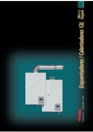
Technical data, TL-S <strong>TMS</strong><br />
Power supply: 24V DC, +/– 10 %, stabilised<br />
Current input, max.: approx. 65 mA<br />
approx. 90 mA in alarm mode<br />
Contact rating: 24V DC, 0.5 A inductive<br />
24 V DC, 1.0 A ohmic<br />
Fuse F1: 1 A<br />
Terminal assignment and functions, TL-S <strong>TMS</strong><br />
X1<br />
X10<br />
X14<br />
S1<br />
X9<br />
X2<br />
X7<br />
3<br />
2<br />
1<br />
3<br />
B<br />
A<br />
1<br />
X6<br />
3<br />
B<br />
A<br />
1<br />
F1<br />
3<br />
2<br />
X12<br />
X8<br />
X3<br />
X4<br />
X1 Socket connector for connection of expansion module<br />
ZM 208<br />
X2 Connection to the internal DCW` devices<br />
X3 Connection to the internal key switch/momentary<br />
contact device<br />
X4 Power supply 24V DC, +/– 10%<br />
X5 Connection to emergency pushbutton<br />
X6 Connection to the TV / DCW`<br />
X7 External emergency pushbutton/smoke detector<br />
X8 PC interface RS 232 / LON adapter<br />
X9 Connection to the firmware programming system<br />
X10 Permanent emergency pushbutton light;<br />
jumper must always be set<br />
X12 Connection to the TL-OM lighting module<br />
X14 Connection to external DCW` devices<br />
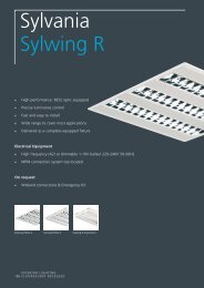
TV<br />
24V<br />
X6<br />
3<br />
B<br />
A<br />
1<br />
3<br />
2<br />
X4<br />
+<br />
Emer- 3<br />
gency 2<br />
PB ext. 1<br />
® DCW<br />
ext.<br />
X7<br />
X14<br />
3<br />
B<br />
A<br />
1<br />
GND<br />
+24V DC<br />
GND<br />
+24V DC<br />
GND<br />
+24V DC<br />
GND<br />
+24V DC<br />
®<br />
DCW bus<br />
X5<br />
Switched voltage for TV<br />
electrical door locking element<br />
+/–10%, Stabilised<br />
power supply<br />
®<br />
DCW bus<br />
Emergency pushbutton/<br />
<strong>DORMA</strong> RM smoke<br />
detector or jumper<br />
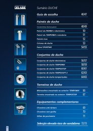
Technical data, TL-S DCW`<br />
Power supply: 24V DC, +/– 10 %, stabilised<br />
Current input, max.: approx. 75 mA<br />
approx. 90 mA in alarm mode<br />
Terminal assignment and functions, TL-S DCW`<br />
X9<br />
X12<br />
X3<br />
ON<br />
X2 Connection to the internal DCW` devices<br />
X3 Connection to the internal key switch/momentary<br />
contact device<br />
X5 Connection to emergency pushbutton<br />
X6 Connection to the TL-S <strong>TMS</strong>/RZ <strong>TMS</strong><br />
X9 Connection to the firmware programming system<br />
X12 Connection to the TL-OM lighting module<br />
S1 Micro-switches for setting the device address:<br />
X6<br />
3<br />
B<br />
A<br />
1<br />
2<br />
2<br />
Switch Address<br />
1 2<br />
0 0 1<br />
1 0 2<br />
0 1 3<br />
1 1 4<br />
GND<br />
+24V DC<br />
1<br />
S1<br />
0<br />
12<br />
®<br />
DCW bus<br />
X2<br />
X5<br />
B 3<br />
A 122<br />
X6<br />
Emergency pushbutton<br />
NC contact<br />
(“Emergency stop” circuit)<br />
<strong>TMS</strong>, GB