TMS DORMA - Quadri Sistemas
TMS DORMA - Quadri Sistemas
TMS DORMA - Quadri Sistemas

You also want an ePaper? Increase the reach of your titles
YUMPU automatically turns print PDFs into web optimized ePapers that Google loves.
<strong>DORMA</strong><br />
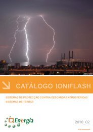
TL-UP S55 DCW`<br />
12<br />
Door Terminal<br />
for installation in<br />
standard switch boxes<br />
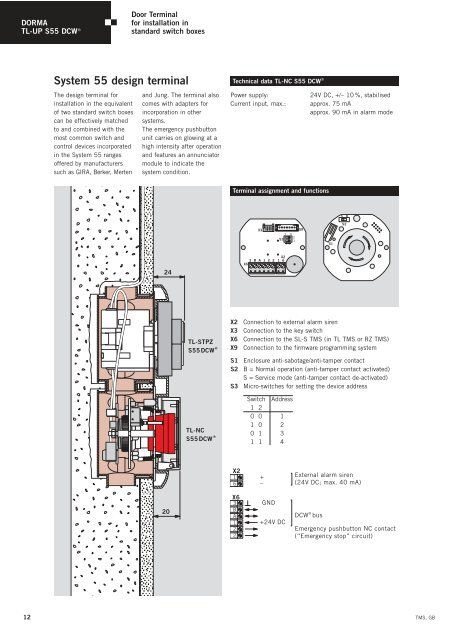
System 55 design terminal<br />
The design terminal for<br />
installation in the equivalent<br />
of two standard switch boxes<br />
can be effectively matched<br />
to and combined with the<br />
most common switch and<br />
control devices incorporated<br />
in the System 55 ranges<br />
offered by manufacturers<br />
such as GIRA, Berker, Merten<br />
and Jung. The terminal also<br />
comes with adapters for<br />
incorporation in other<br />
systems.<br />
The emergency pushbutton<br />
unit carries on glowing at a<br />
high intensity after operation<br />
and features an annunciator<br />
module to indicate the<br />
system condition.<br />
24<br />
20<br />
TL-STPZ<br />
S55DCW ®<br />
TL-NC<br />
S55DCW ®<br />
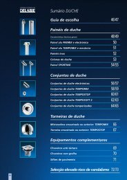
Technical data TL-NC S55 DCW`<br />
Power supply: 24V DC, +/– 10 %, stabilised<br />
Current input, max.: approx. 75 mA<br />
approx. 90 mA in alarm mode<br />
Terminal assignment and functions<br />
X2<br />
1<br />
6<br />
X6<br />
3<br />
B<br />
A<br />
1<br />
2<br />
2<br />
X3<br />
X9<br />
1 0<br />
2<br />
S3<br />
1<br />
ON<br />
X2<br />
3 B A 1 2 2 1 6<br />
X6<br />
X2 Connection to external alarm siren<br />
X3 Connection to the key switch<br />
X6 Connection to the SL-S <strong>TMS</strong> (in TL <strong>TMS</strong> or RZ <strong>TMS</strong>)<br />
X9 Connection to the firmware programming system<br />
S1 Enclosure anti-sabotage/anti-tamper contact<br />
S2 B = Normal operation (anti-tamper contact activated)<br />
S = Service mode (anti-tamper contact de-activated)<br />
S3 Micro-switches for setting the device address<br />
Switch Address<br />
1 2<br />
0 0 1<br />
1 0 2<br />
0 1 3<br />
1 1 4<br />
+<br />
–<br />
GND<br />
+24V DC<br />
S1<br />
S B<br />
S2<br />
External alarm siren<br />
(24V DC; max. 40 mA)<br />
DCW ® bus<br />
Emergency pushbutton NC contact<br />
(“Emergency stop” circuit)<br />
<strong>TMS</strong>, GB