TMS DORMA - Quadri Sistemas
TMS DORMA - Quadri Sistemas
TMS DORMA - Quadri Sistemas

Create successful ePaper yourself
Turn your PDF publications into a flip-book with our unique Google optimized e-Paper software.
<strong>DORMA</strong> TV 50x DCW` Door Locking Element<br />
24<br />
Door locking element for<br />
concealed top jamb/frame<br />
mounting. Also suitable as<br />
an electric keep for emergency<br />
exit doors. Integrated<br />
feedback contacts for monitoring<br />
the active/inactive<br />
conditions. Suitable for<br />
doors with both over-rebated<br />
and flush meeting stiles.<br />
TV 501/502<br />
22,4<br />
15 ø 7<br />
35<br />
48<br />
TV 505/506<br />
22,4<br />
3<br />
42<br />
39<br />
42<br />
1,5 23<br />
38<br />
134<br />
134<br />
160<br />
43<br />
30<br />
3 22<br />
20 180<br />
200<br />
186<br />
220<br />
10 200<br />
7<br />
Max. holding force as per<br />
German DIBt code of practice<br />
entitled “Requirements<br />
for electrical locking<br />
systems on doors in emergency<br />
escape routes”<br />
(EltVTR).<br />
Connection to the <strong>DORMA</strong><br />
<strong>TMS</strong> door management<br />
system via lock adapter<br />
TV<br />
505<br />
14<br />
25<br />
TV<br />
501<br />
20<br />
30<br />
43<br />
49<br />
43<br />
59,5 49<br />
ø 6,5<br />
5,5<br />
64,5<br />
TV<br />
506<br />
TV<br />
502<br />
TV 50x DCW ® . The lock<br />
adapter can also be installed<br />
in the TLG-<strong>TMS</strong> door terminal<br />
or in the RZ <strong>TMS</strong> emergency<br />
exit control unit.<br />
F Approval certification<br />
In Germany, installation on<br />
DIN fire and smoke rated<br />
doors is only permitted pro-<br />
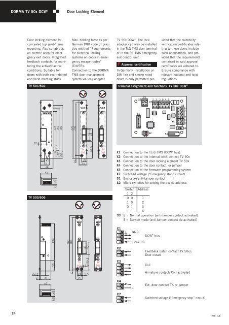
Terminal assignment and functions, TV 50x DCW`<br />
X2<br />
X5<br />
2 1<br />
0<br />
FK<br />
1<br />
ON<br />
2 3 3 B A 1<br />
X7 X1<br />
S2<br />
vided that the suitability<br />
verification certificates relating<br />
to these doors include<br />
such applications, and provided<br />
that the requirements<br />
contained in said approval<br />
certificates are adhered to.<br />
Ensure compliance with<br />
relevant national and local<br />
regulations.<br />
S1<br />
X4<br />
S<br />
X3<br />
2<br />
3<br />
1<br />
4<br />
18 19<br />
B<br />
S3<br />
X1 Connection to the TL-S <strong>TMS</strong> (DCW ® bus)<br />
X2 Connection to the internal latch contact TV 50x<br />
X3 Connection to the door locking element TV 50x<br />
X4 Connection to the door contact, or jumper<br />
X5 Connection to the firmware programming system<br />
X7 Switched voltage (“Emergency stop” circuit)<br />
S1 Enclosure anti-tamper contact<br />
S2 Micro-switches for setting the device address:<br />
Switch Address<br />
1 2<br />
0 0 1<br />
1 0 2<br />
0 1 3<br />
1 1 4<br />
S3 B = Normal operation (anti-tamper contact activated)<br />
S = Service mode (anti-tamper contact de-activated)<br />
X1<br />
3<br />
B<br />
A<br />
1<br />
X2<br />
FK<br />
FK<br />
X3<br />
2<br />
3<br />
1<br />
4<br />
X4<br />
18<br />
19<br />
X7<br />
2<br />
3<br />
GND<br />
+24V DC<br />
+<br />
®<br />
DCW bus<br />
Feedback (latch contact TV 50x):<br />
Door closed<br />
Coil<br />
Armature contact: Coil activated<br />
Ext. door contact TK or jumper<br />
Switched voltage (“Emergency stop” circuit)<br />
<strong>TMS</strong>, GB