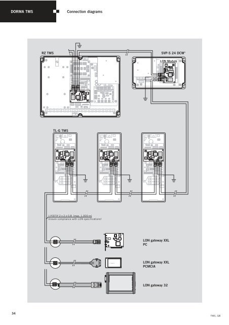
<strong>DORMA</strong> <strong>TMS</strong> Connection diagrams 34 RZ <strong>TMS</strong> SVP-S 24 DCW ® TL-G <strong>TMS</strong> I-Y(ST)Y 2 x 2 x 0,8 (max. 1.000 m) Ensure compliance with LON specifications! X2 X2 X3 X3 PCC-10 Netw ork Adapter X1 LON Module LON gateway XXL PC LON gateway XXL PCMCIA LON gateway 32 <strong>TMS</strong>, GB
<strong>DORMA</strong> <strong>TMS</strong> Safety information <strong>TMS</strong>, GB <strong>DORMA</strong> emergency exit systems are designed, developed and manufactured in accordance with the latest state of the art and in line with recognised technical safety regulations and standards. They meet the requirements of the code of practice entitled “Requirements for electrical locking systems on doors in emergency escape routes” (EltVTR, December 1997 edition) published in Bulletin 5/98 of the German Institute for Building Technology, Berlin. Test and approval certificates issued by the MPA NRW (Material Testing Authority) and VdS Cologne (Association of Property Insurers) are available. Compliance with the following instructions by the installer and operator is imperative to ensuring that these devices do not impede unhindered escape of persons in the event of a hazard-related emergency. Usage Emergency exit systems are electrical locking systems for doors in emergency exits and escape routes. They are designed in order to prevent improper or unauthorised usage of the associated access points. When installing and using <strong>DORMA</strong> emergency exit systems, compliance with the technical data and the requirements emanating from prevailing local conditions is essential. Preliminary building enquiry / Planning application / Approval procedure – The German example – Emergency exit systems do not fall under the compass of current building law and approval is subject to a discretionary exemption in the sense of § 67 Musterbauordnung [Outline building regulations]. In addition, the requirements according to DIBt 5/98 should also be regarded as ancillary regulations that need to be incorporated within the building approval process for the project in hand. Planning and installation A <strong>DORMA</strong> emergency exit system consists at least of the components <strong>TMS</strong> door terminal/central control station and TV electrical door locking element. Depending on the design of the emergency exit control, the following components may also be connected to the system: Key switch or access control system, monitoring and control unit, emergency escape lock with automatic locking action (switch-monitored or motor lock), flashing lamp or external alarm siren, automatic swing door operator, power pack with emergency power supply, fire alarm and/or hazard alert system, smoke switch. The electrical door locking element may only be used on emergency exit doors in conjunction with products approved by <strong>DORMA</strong>. The door terminal (local system release/emergency opening of door) should be mounted in the immediate vicinity of the door handle so that the centre of the emergency pushbutton is at a height of 850 mm to max. 1200 mm above the finished floor level. The emergency pushbutton must be indicated with an adhesive label showing the inscription “Emergency Exit”. The adhesive label should be attached such that the arrow points to the emergency pushbutton. In buildings with automatic fire extinguishing equipment, fire alarm or other hazard alert systems, the emergency exit doors with electrical anti-tamper protection must be automatically released for escape on response or activation of these systems. If, during building usage, there is a constantly manned central control centre with a direct view of the emergency exit doors, the emergency exit release/de-activation switching operation can also be performed from this position. The properties and characteristics of the fire and smoke rated doors (fire resistance time, smoke retention/sealing function and automatic closing action) must not be impaired by the installation of the electrical door locking device. In Germany, modifications to fire doors or other fire barriers which are necessary for the installation of an electrical door locking element and which go beyond the modifications indicated as permissible in Bulletin 1/1996 of the DIBt, require general building approval and/or agreement of the authorities responsible in each individual case. Consult local/national authorities for guidance. Only use <strong>DORMA</strong> spare parts or <strong>DORMA</strong> approved accessories. Any work on electrical equipment not operating on protective low voltage must always be performed by suitably qualified electricians. Installation, commissioning and maintenance work may only be performed by qualified personnel authorised by <strong>DORMA</strong>. The keys for the door terminal and emergency exit control box must be kept secure. Keys for products not operating on protective low voltage may only be handed over to suitably qualified electricians. Standards and regulations Compliance with all relevant national or regional regulations, standards, guidelines and directives (latest edition in each case) must be ensured. The following publications provide a useful general regulatory framework for ensuring system safety: – DIBt bulletin 5/98 – “Requirements for electrical locking systems on doors in emergency escape routes” (EltVTR), – DIBt bulletin 1/96 – Modifications to fire doors and fire rated barriers. – DIN VDE 0100, 0800, 0815 – Regulations governing the installation of electrical equipment – DIN 0833 – Part 1-3 – Regulations governing hazard alert systems for fire, burglary and robbery detection and alarm – German building regulations list A, Part 1 – Special building regulations – prEN 13637 – Building Hardware – Electrically controlled emergency exit systems 35
- Page 1 and 2: DORMA Door Management System TMS
- Page 3 and 4: TMS, GB b Additional information re
- Page 5 and 6: TMS, GB Data and features Function
- Page 7 and 8: TMS, GB Systematic down to the last
- Page 9 and 10: TMS, GB Specification text Order No
- Page 11 and 12: TMS, GB Specification text Order No
- Page 13 and 14: TMS, GB Specification text Order No
- Page 15 and 16: TMS, GB Specification text Order No
- Page 17 and 18: TMS, GB TV-Z TV 1 DCW ® TL TMS TV-
- Page 19 and 20: TMS, GB Specification text Order No
- Page 21 and 22: TMS, GB TV-Z TV 2 DCW ® TL TMS TV-
- Page 23 and 24: TMS, GB Specification text Order No
- Page 25 and 26: TMS, GB Technical data, TV 5xx Powe
- Page 27 and 28: TMS, GB Specification text Order No
- Page 29 and 30: TMS, GB Specification text Order No
- Page 31 and 32: TMS, GB RZ-TMS NT-S 24-1.5 TL-S DCW
- Page 33: TMS, GB TMS + TE 3x X11 X10 X9 X8 S