CT4860 STRUCTURAL DESIGN OF PAVEMENTS
CT4860 STRUCTURAL DESIGN OF PAVEMENTS
CT4860 STRUCTURAL DESIGN OF PAVEMENTS

Create successful ePaper yourself
Turn your PDF publications into a flip-book with our unique Google optimized e-Paper software.
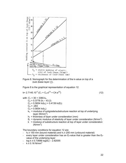
Figure 8. Nomograph for the determination of the k-value on top of a<br />
(sub-)base layer (1).<br />
Figure 8 is the graphical representation of equation 12:<br />
k= 2.7145.10 -4 (C1 + C2.e C3 + C4.e C5 ) (12)<br />
with: C1 = 30 + 3360.ko<br />
C2 = 0.3778 (hf – 43.2)<br />
C3 = 0.5654 ln(ko) + 0.4139 ln(Ef)<br />
C4 = -283<br />
C5 = 0.5654 ln(ko)<br />
ko = modulus of subgrade/substructure reaction at top of underlying<br />
layer (N/mm 3 )<br />
hf = thickness of layer under consideration (mm)<br />
Ef = dynamic modulus of elasticity of layer under consideration (N/mm 2 )<br />
k = modulus of substructure reaction at top of layer under consideration<br />
(N/mm 3 )<br />
The boundary conditions for equation 12 are:<br />
- hf ≥ 150 mm (bound material) and hf ≥ 200 mm (unbound material)<br />
- every layer under consideration has an Ef-value that is greater than the Efvalue<br />
of the underlying layer<br />
- log k ≤ 0.73688 log(Ef) – 2.82055<br />
- k ≤ 0.16 N/mm 3<br />
22