
You also want an ePaper? Increase the reach of your titles
YUMPU automatically turns print PDFs into web optimized ePapers that Google loves.
4.6<br />
Cooling units<br />
Electrical connection and control<br />
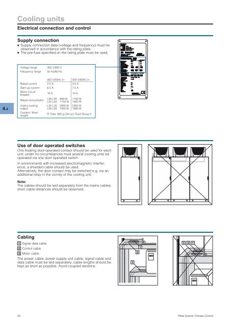
Supply connection<br />
● Supply connection data (voltage and frequency) must be<br />
observed in accordance with the rating plate.<br />
● The pre-fuse specified on the rating plate must be used.<br />
Voltage range 400 V/460 V<br />
Frequency range 50 Hz/60 Hz<br />
400 V/50Hz 3~ 400 V/60Hz 3~<br />
Rated current 2.5 A 3.0 A<br />
Start-up current 6.5 A 7.5 A<br />
Motor circuit<br />
breaker<br />
10 A 10 A<br />
Rated consumption<br />
L35 L35<br />
L35 L50<br />
930 W<br />
1150 W<br />
1150 W<br />
1400 W<br />
Useful cooling L35 L35 2000 W 2350 W<br />
output<br />
L35 L50 1450 W 1690 W<br />
Coolant / filled<br />
weight<br />
R 134a, 950 g (34 oz), Fluid Group 2<br />
Use of door operated switches<br />
One floating door-operated contact should be used for each<br />
unit; under no circumstances must several cooling units be<br />
operated via one door operated switch.<br />
In environments with increased electromagnetic interference,<br />
a shielded cable should be used.<br />
Alternatively, the door contact may be switched e.g. via an<br />
additional relay in the vicinity of the cooling unit.<br />
Note:<br />
The cables should be laid separately from the mains cables;<br />
short cable distances should be observed.<br />
Cabling<br />
1 Signal data cable<br />
2 <strong>Control</strong> cable<br />
3 Motor cable<br />
The power cable, power supply unit cable, signal cable and<br />
data cable must be laid separately; cable lengths should be<br />
kept as short as possible. Avoid coupled sections.<br />
40 <strong>Rittal</strong> <strong>System</strong> <strong>Climate</strong> <strong>Control</strong><br />
3<br />
2<br />
1<br />
3<br />
2<br />
1